Mitsubishi EMU4-BM1-MB User manual

Energy Measuring Unit Energy Measuring Standard Model
Energy Measuring Unit Energy Measuring High Performance Model
MODEL
EMU4-BM1-MB
EMU4-HM1-MB
User’s Manual (Details)
●Before operating the instrument, you should first read thoroughly this operation manual for
safe operation and optimized performance of the product.
Deliver this user’s manual to the end user.

1
Safety precautions
Thank you for purchasing the Energy Measuring Unit (EcoMonitorPlus).
・
This manual describes setup and usage for the Energy Measuring Unit. Before using the product, please read this manual
carefully to ensure correct use. Especially, in the case of where this unit is to be installed, please read “1. Precautions for Use” to
ensure correct use.
・Make sure that the end users read this manual and then keep the manual in a safe place for future reference.
・Make sure to deliver this manual to the end-user.
・If you are considering using this unit for special purpose such as nuclear power plants, aerospace, medical care or passenger
vehicles please refer to our sales representative.(For details, please see at the end of this manual.)
■ Notations in this manual
Use the following marks in this manual.
Mark
Meaning of the icons
Danger
Indicates that incorrect handling may result in death or severe injury, ignoring this marking.
Caution
Indicates that incorrect handling may result in injury or property damage, ignoring this marking.
Supplement
Indicates that precautions to avoid a malfunction and to work the unit properly.
Indicates that the pages described that related matters.
■ Checking package contents
This following items for this device and included in package. Check that no items are missing.
or
Energy Measuring Unit x1
User’s Manual (Digest) x1
Feature
This Energy Measuring unit can measure various types of electric quantity such as voltage, current, electric power and electric
energy.
The measured data can be sent to the high-end device, such as a monitoring device by MODBUS RTU communication function.
This Energy Measuring unit has one external input terminal, which can switch between pulse input and contact input.
Production quantity and water, gas, air (other than electricity) can be measured in the pulse input setting. (Model: EMU4-HM1-MB)
Monitoring of condition and alarm, measurement of operating time and electric energy during operation can be done in the contact
input setting.
Adding this unit enables measurement of multiple circuits.
For the single-phase 2-wire, this Energy Measuring Unit can measure two circuits of the system with the same voltage.
This Energy Measuring unit can measure energy without input voltage by use the simple measuring function.
MODBUS is a registered trademark of SCHNEIDER ELECTRIC USA, INC.
This unit cannot be used for deal and proof of electric energy measurement stipulated in the
measurement law. Please use the certified watt-hour meter to be used for deal and proof of electric
energy measurement stipulated.

2
Table of Content
Safety precautions..................................................................................................................................................... 1
Feature ........................................................................................................................................................................ 1
Table of Content......................................................................................................................................................... 2
1. Precautions for Use............................................................................................................................................... 3
1.1 Precautions for Operating Environment and Conditions ........................................................................... 3
1.2 Matters concerning the precaution before use........................................................................................... 3
1.3 Installation and Wiring Precautions ............................................................................................................ 3
1.4 Precautions for Use .................................................................................................................................... 4
1.5 Maintenance Precautions ........................................................................................................................... 4
1.6 Storage Precautions ................................................................................................................................... 4
1.7 Disposal Precautions .................................................................................................................................. 4
1.8 About packaging materials and this manual .............................................................................................. 5
2. Disclaimer ............................................................................................................................................................... 5
3. Name and function of each part .......................................................................................................................... 5
3.1 Name of each part ...................................................................................................................................... 5
3.2 Indication and function of LEDs.................................................................................................................. 6
3.3 2 circuits measuring in 1P2W ..................................................................................................................... 6
4. Attaching and removing the unit ......................................................................................................................... 7
4.1 Mounting on IEC rail ................................................................................................................................... 7
4.2 Mounting on JIS agreement type attachment ............................................................................................ 7
5. Procedure for wiring.............................................................................................................................................. 8
5.1 Wiring for EMU4-BM1-MB.......................................................................................................................... 8
5.2Wiring for EMU4-HM1-MB........................................................................................................................ 10
5.3 Precautions for the connection wire ......................................................................................................... 12
6. Setting ................................................................................................................................................................... 15
6.1 Setting data ............................................................................................................................................... 15
6.2 Initialization of related item by changing the setup .................................................................................. 20
7. Operation .............................................................................................................................................................. 22
7.1 Measurement ............................................................................................................................................ 22
7.2 Upper/lower limit monitoring function ....................................................................................................... 26
7.3 Simple measurement................................................................................................................................ 29
8. Device operation.................................................................................................................................................. 33
8.1 Resolution of measuring data................................................................................................................... 33
8.2 Restrictions of measured data................................................................................................................. 34
9.
Reference ............................................................................................................................................................ 35
9.1 In case you think the unit is in failure........................................................................................................ 35
9.2 After-sales service..................................................................................................................................... 36
9.3 Q&A........................................................................................................................................................... 36
10. Requirement for the compliance with EMC Directives EMC ....................................................................... 39
11. Specifications..................................................................................................................................................... 40
11.1 Common specifications........................................................................................................................... 40
11.2 Specifications of MODBUS communications......................................................................................... 42
12. Option devices ................................................................................................................................................... 43
12.1 About option devices .............................................................................................................................. 43
12.2 Specifications of option devices ............................................................................................................. 44
12.3 External dimensions of option devices................................................................................................... 46
13. External dimensions ......................................................................................................................................... 54
14. Index .................................................................................................................................................................... 55

3
1. Precautions for Use
1.1 Precautions for Operating Environment and Conditions
This unit is premised on being used in pollution degree 2 (Note 1) environment. When used in higher pollution degree, protect this
unit from pollution on another device side to be incorporated.
Over voltage category of measuring circuit in this unit is CAT II (Note 1), and that of auxiliary power circuit (MA, MB) is CAT II (Note
1).
Do not use this product in the places listed below. Failure to follow the instruction may cause malfunctions and a life decrease of
product.
- Places the Ambient temperature exceeds the range -5 - +55°C.
- Places the average daily temperature exceeds 35°C.
- Places the Relative humidity exceeds the range 30-85% or places with dewfall.
- Vibration and impact exceed the specifications.
- Dust, corrosive gas, saline and oil smoke exist.
- Places exposed to direct sunlight.
- Places exposed to rain or water drop.
- Places in strong electromagnetic field or places large amounts of external noise exist.
- Places metal fragments or conductive substances are flying.
- Altitude exceeds 2000m.
Note 1: For the definition of the pollution degree and the over voltage category, refer to EN61010-1/2010.
1.2 Matters concerning the precaution before use
Use the unit in the specified usage environment and conditions.
To set this unit, dedicated small-size display unit (EMU4-D65) is necessary. For the setting method, refer to User’s manual
(Details) of the display unit.
1.3 Installation and Wiring Precautions
Danger
・Shut off the external power supply for the unit in all phases before installing or wiring. Failure to do so
may cause an electric shock or damage of this unit.
・
Work under the electric outage condition when installing and wiring. Failure to do so may cause electric
shock, a failure of the unit, a fire etc.
Caution
<Precautions for Electric work>
・Any person who is involved in the installation and the wiring of this unit should be fully competent to do this work.
・When tapping or wiring, take care not to entering any foreign objects such as chips and wire pieces into this unit.
・Check the connection diagram when wiring. Wrong wiring may cause failure of the unit, a fire or electric shock.
・For protection against noise, transmission lines and input/output lines shall not be placed close to or bound
together with the power lines and high-voltage lines.
・The wires to be connected to this unit shall be placed in a duct or fixed together by cramping. If the electric wires are not
placed in the duct or cramped together, loosen wires or their movement or careless stretch may cause a breakage of
the unit or wire or a malfunction due to poor contact of electric wires.
・If transmission lines and input/output lines are placed close to or bound together with the power lines and high-voltage
lines, keep distance as below between them.(Except for the input side of terminal block)
Condition
Distance
Power line 600V or less
Other power line
300mm or longer
600mm or longer
<Connection of terminal block>
・Strip the wires with proper length. Overlong stripping length may cause short to next wire. Shorter stripping length may
cause contact failure.
・Take care not to short to next terminal by a filament. (Do not plate the wires with solder.)
・Do not connect three or more wires to one terminal of a terminal block for preventing loose contact and wires dropout.
・Use appropriate size of electric wires. If inappropriate size of electric wire is used, it may cause a fire due to generated
heat.
・Tighten the screw within the specified torque. Under tightening can cause drop of the screw, short circuit or malfunction.
Over tightening can damage the screw and/or unit, resulting in drop, short circuit or malfunction.
・After tightening the screws, be sure to check all the screws tightened. Loose screw may cause malfunction of the unit,
a fire or electric shock.
・Be sure to attach the terminal cover to prevent electric shock.
・Use the crimp-type terminal appropriated for the size of electric wires. If inappropriate crimp-type terminal is used, a wire
breakage or a contact failure may occur, which may cause a device malfunction, a failure, a burnout or a fire.
・Frame GND terminal must be grounded according to the D-type ground (ground resistance is not exceed 100Ω).
・Do not directly touch any conductive part of the unit. Doing so can cause electric shock, failure or malfunction of the
unit.
・
Do not input voltage and current at NC terminals. Doing so can cause failure or malfunction of the unit.

4
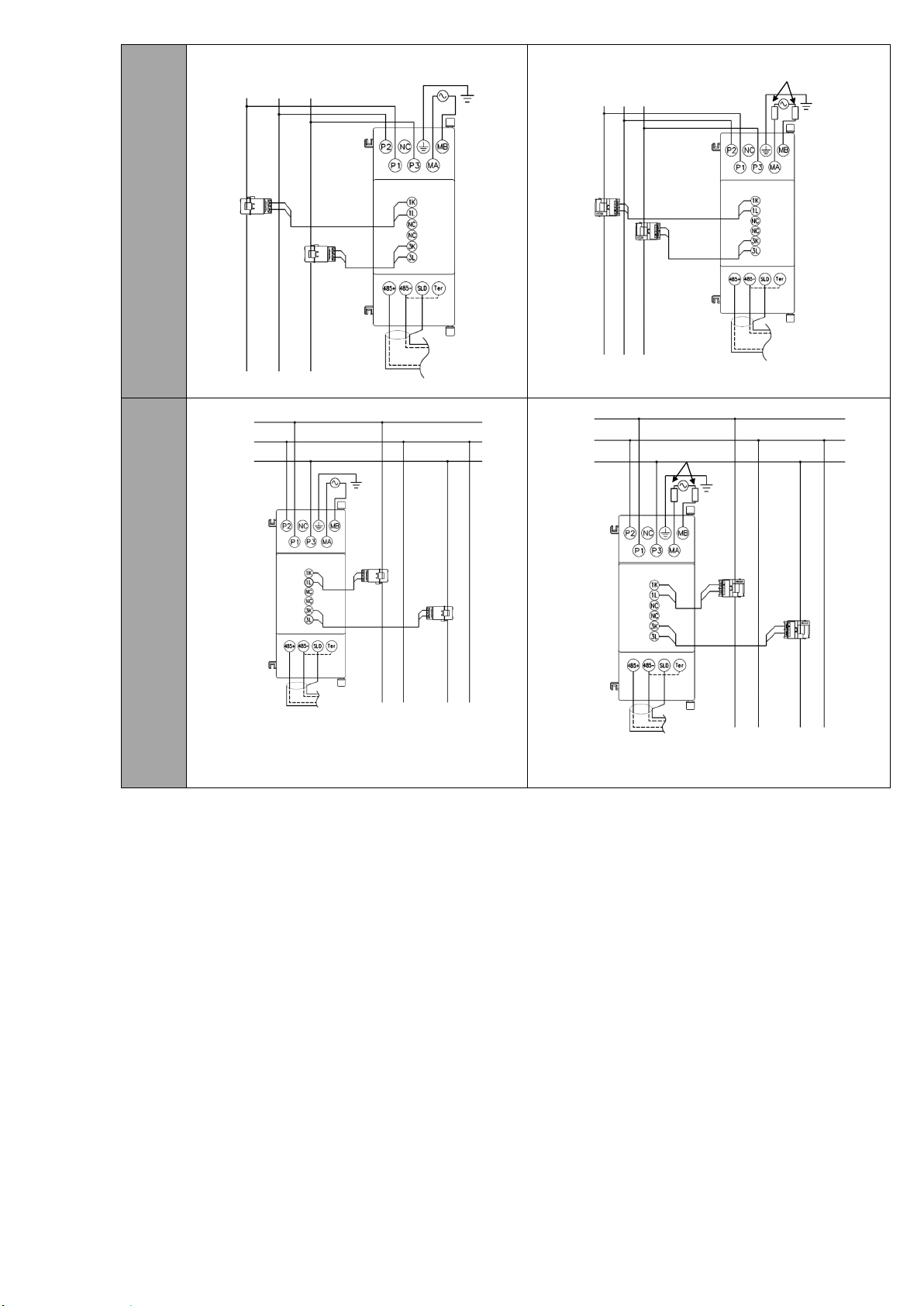
<Connection with the current sensor>
・When using this product, make sure to use it in combination with current sensor (EMU-CT**, EMU-CT**-A. EMU2-CT5
and EMU2-CT5-4W). This product cannot connect with the secondary side (5A) of current transformer. Please not to
exceed the rating of this product for input of current sensor. For further details, please refer to current sensor manual to
maintain the functionality and the accuracy of this product.
・The dedicated current sensor (EMU-CT**, EMU-CT**-A) is used only for low voltage circuit. It cannot be used for a high
voltage circuit. EMU2-CT5 and CT5-4W should be used with the secondary side (5A) of transformer transfixed. If it is
connected with a high-voltage circuit by mistake, it may cause a burnout of the device and a fire. It is critically dangerous.
For the allowable maximum voltage of current sensor, refer to “12. Option devices” in this manual.
・The dedicated current sensor has a polarity (directionality). Be careful about it when installing the unit.
・If the wires connected to this unit are strongly pulled off, it may cause a malfunction or a breakage to the unit or the wire.
<Connection of frame GND terminal>
・Do not exceed the specified voltage when doing an insulation resistance test and a commercial frequency withstand
voltage test.
・Frame FG terminal must be grounded according to the D-type ground.
・To prevent persons with little knowledge about electric equipment from electric shock, panel must be taken either
following measure.
Lock the panel so that only those who get an education about electric equipment and have sufficient knowledge can
unlock, or shut off power supply automatically by opening the panel.
Cover the dangerous part of this unit.
1.4 Precautions for Use
This unit cannot be used for deal and proof of electric energy measurement stipulated in the measurement law.
Before operating the product, check that active bare wire and so on does not exist around the product. If any bare wire exists,
stop the operation immediately, and take an appropriate action such as isolation protection.
In the event of a power outage during the setting by Display unit / Communication line, the Energy Measuring unit is not set
correctly. Please set again after power recovery.
Caution
Do not disassemble or modify this unit. It may cause failure, malfunction, injury or fire.
Use this unit within the ratings specified in this manual. If it is used outside the ratings, it may cause not only
malfunction or failure but also fire burnout.
The secondary side of the models EMU2-CT5, EMU-CT50, EMU-CT100, EMU-CT250,EMU-CT50-A, EMU-CT100-A,
EMU-CT250-A, EMU-CT400-A, EMU-CT600-A is equipped with the protective circuit against opening of secondary
terminals. Opening them during the wiring work causes no problems. However, for safety, please do not continuously
energize the module with the terminals open.
The current sensors dedicated to this unit EMU-CT400/600 resemble the split current transformer for general gauges
CW-5SL closely in appearance. However, characteristics are completely different. Be sure to connect the dedicated
current sensor. Connecting CW-5SL to this unit directly may cause failure of the device, a burnout or a fire.
Push the RESET switch with an appropriate force (1.6N). The addition of force than necessary, it may cause a
malfunction or failure of the Unit.
1.5 Maintenance Precautions
Use a soft dry cloth to clean off dirt of the unit surface. Do not let a chemical cloth remain on the surface for an extended period
of time nor wipe the surface with thinner or benzene.
Check for the following items to use this unit properly for long time.
(1) Daily maintenance
(a) No damage on this unit
(b) No abnormality with LCD indicators
(c) No abnormal noise, smell or heat
(2) Periodical maintenance (Once every 6 months to 1 year)
- No looseness with installation and wire connection
Caution
Do periodical maintenance under the electric outage condition. Failure to do so may cause
electric shock, failure of the unit or a fire. Tighten the terminal regularly to prevent a fire.
1.6 Storage Precautions
To store this unit, turn off the power and remove wires, and put it in a plastic bag.
For long-time storage, avoid the following places. Failure to follow the instruction may cause a failure and reduced life of the unit.
- Places the Ambient temperature exceeds the range -10 - +60°C.
- Places the average daily temperature exceeds 35°C.
- Places the Relative humidity exceeds the range 30-85% or places with dewfall.
- Vibration and impact exceed the specifications.
- Dust, corrosive gas, saline and oil smoke exist.
- Places metal fragments or conductive substances are flying.
- Place where metallic particles or inductive substances are dispersed
1.7 Disposal Precautions
When disposing of this unit, treat it as industrial waste.

5
1.8 About packaging materials and this manual
For reduction of environment load, packaging materials are produced with cardboard, and this manual is printed on recycled
paper.
2. Disclaimer
It is prohibited to reprint or copy all contents of this document in any form without our permission.
The contents of this document will be updated to follow revisions to software and hardware, however under unavoidable
circumstances it may not be synchronized.
3. Name and function of each part
3.1 Name of each part
(1)EMU4-BM1-MB (2)EMU4-HM1-MB
Connector(small-size display unit)
Connect the display unit.
Reset button
Reset main unit.
LED
Operation mode is
displayed.
(Please reference to 4.2
LED display and function)
Input current
(1K,1L,3K,3L)
Connect the secondary
output of the dedicated
current sensor connected to
the measurement circuit’s
current wire.
※Please setup input current
to 3K,3L
when measuring 2 circuits
by a terminal in 1P2W
(Please reference to the 6.1
Wiring)
Input voltage(P1,P2,P3)
Connect the voltage input wire
for the measuring circuit.
Auxiliary power(MA,MB)
Connect the auxiliary power supply.
MODBUS communication terminal(485+、485-、SLD、Te r)
485+、485-:MODBUS connect the communication wire.
SLD:Connect to ground (D type ground).
Ter :Connect with “485- “terminal (the unit at end of the link)
Frame GND(FG)
Connect to ground (D type ground).
Connector(small-size display unit)
Connect the display unit.
Reset button
Reset main unit.
LED
Operation mode is
displayed.
(Please reference to 4.2 LED
display and function)
Input current
(1K, 1L, 2K, 2L, 3K, 3L)
Connect the secondary
output of the dedicated
current sensor connected to
the measurement circuit’s
current wire.
※Please setup input current
to 3K,3L
when measuring 2 circuits
by a terminal in 1P2W
(Please reference to the 6.1
Wiring)
MODBUS communication terminal(485+,485-,SLD、Te r )
485+、485-:MODBUS connect the communication wire.
SLD:Connect to ground (D type ground).
Ter:Connect with “485- “terminal (the unit at end of the link)
Output terminal(X1,COMX1)
Connect to pulse/contact output.
Output terminal(Y1,COMY1)
Connect to pulse/contact output.
Input voltage
(P1/P1,P2/P0,P3/P3,NC/P2)
Connect the voltage input wire
for the measuring circuit.
Auxiliary power(MA,MB)
Connect the auxiliary power supply.
Frame GND(FG)
Connect to ground (D type ground).
(3)Back view and side view
Connector
(Extension)
Connect to
extension units.
IEC rail fixture
Connector
(Option devices)
Connect to option
Units.
Back view
Right side
Left side
Connection stop
This is used to connect the
extension unit to the Energy
Measuring Unit.
Connection stop
This is used to connect the
option unit to the Energy
Measuring Unit.

6
3.2 Indication and function of LEDs
The names and operations of LEDs are as follows.
(Note 1) For details, refer to Chapter 14 "Error codes" of “User’s Manual (Details)”.
(Note 2) Only in the case of single-phase 2-wire system, these indicate the status of the measured circuit of the current sensor in
No.1 side of the circuit A2. (See 3.3)
3.3 2 circuits measuring in 1P2W
This unit can measure 2 circuits in the case wiring type 1P2W.
It is a function to measure the 1P2W of 1-N and 3-N branched from 1P3W. (Reference to Figure 3.3.2)
2 circuits measuring can be conducted when current sensor is connected to 1 side (1K, 1L) and 3 side (3K, 3L).
(Reference to Figure 3.3.1 and 3.3.2)
Please reference to 5 chapter about wiring.
Please reference to 6.1 section and EMU4-D65 User’s Manual (Details) when setup for measuring 2 circuits
You can only measure same primary current value in 1 side and 3 side when 2 circuit measuring mode.
Circuit A1
The circuit connected to
1K and 1L of SENSOR
A becomes circuit A1.
Circuit A2
The circuit connected to
3K and 3L of SENSOR A
becomes circuit A2.
k
l
K
L
k
l
K
L
Load A1
Load A2
RS-485(MODBUS RTU)
K
1
N
3
Power
supply
side
Load
side
Figre3.3.1 Figre3.3.2
Name
Color
Function
Status
RUN LED
Red
Indicate operating status of this unit.
ON: Normal condition
OFF: Power off or hardware failure
(Note 1)
MEA. A1 LED
Red
Indicate measuring status of the circuit
A1.
ON: In the middle of measuring
OFF: Halting measurement
MEA. A2 LED
(Note 2)
Red
Indicate measuring status of the circuit
A2.
ON: In the middle of measuring
OFF: Halting measurement
ALM. A1 LED
Red
Indicate occurrence status of upper/lower
limit alert of the circuit A1.
ON: An error occurs (Note 1)
Blink: Upper/lower limit alert is issued
OFF: No alert
ALM. A2 LED
(Note 2)
Red
Indicate occurrence status of upper/lower
limit alert of the circuit A2.
ON: An error occurs (Note 1)
Blink: Upper/lower limit alert is issued
OFF: No alert

7
4. Attaching and removing the unit
Caution
・
Any person who is involved in the installation and the wiring of this unit should be fully competent to do this work.
4.1 Mounting on IEC rail
4.2 Mounting on JIS agreement type attachment
• Applicable IEC rail
(35mm)
•Mounting
• Removing
(1) Pull IEC rail fixture downward
(2) Pull the unit
(1) Hold the unit and pull IEC
rail fixture downward
IEC rail
(4) Push the IEC rail
fixture upward
(3) Push in
(2) Catch
7.3 or more
• Mounting
• JIS agreement type
attachment
• Removing
Spring fitting
Attachment
panel
Hook
(2) Hitch 3 chases at
upper part of the
module to the hook
on the attachment
plate
(3) Push the module down and fit in the
spring fitting in chases at the lower
part of the module.
(1) Push the stopper of the IEC rail
above
(1) Push down the
spring fitting
(2) Lift the lower part of
module slowly and
remove in reverse order
of Attaching.

8
5. Procedure for wiring
Follow the wiring diagram for external connections of this unit.
To use this unit, Base unit (EMU4-BM1-MB、EMU4-HM1-MB、EMU4-LG1-MB) is necessary.
When using this unit, current sensor (EMU-CT***, EMU-CT***-A, EMU2-CT5 or EMU2-CT5-4W) is necessary
(Note) “***” indicates the rated current of the current sensor (50/100/250/400/600).
Please do not use EMU-CT*** type sensor and EMU-CT***-A type sensor with mixture.
5.1 Wiring for EMU4-BM1-MB
When UL compliance is unnecessary
When UL compliance is necessary
Usable current sensor
Models
Support
remark
EMU-CT50
◯
Connection with
general wire
EMU-CT100
◯
EMU-CT250
◯
EMU-CT400
◯
EMU-CT600
◯
EMU-CT5-A
◯
EMU-CT50-A
◯
EMU-CT100-A
◯
EMU-CT250-A
◯
EMU-CT400-A
◯
EMU-CT600-A
◯
EMU2-CT5
◯
Connection with
dedicated cable
EMU2-CT5-4W
×*1
*1: EMU2-CT5-4W is only used 3phase-4wire system.
Usable current sensor
Models
Support
remark
EMU-CT50
◯
Connection with
general wire
EMU-CT100
◯
EMU-CT250
◯
EMU-CT400
×
EMU-CT600
×
EMU-CT5-A
×
EMU-CT50-A
×
EMU-CT100-A
×
EMU-CT250-A
×
EMU-CT400-A
◯
EMU-CT600-A
◯
EMU2-CT5
◯
Connection with
dedicated cable
EMU2-CT5-4W
×*1
*1: EMU2-CT5-4W is only used 3phase-4wire system.
1P2W
Power supply side
Load side
K
L
RS485 (MODBUS RTU)
k
l
1
2
Power supply side
Load side
K
L
RS485 (MODBUS RTU)
k
l
Fuse 0.5A
1
2

9
1P3W
3P3W
Power supply side
Load side
K
L
RS-485 (MODBUS RTU)
k
l
K
L
k
l
1
2
3
1
N
3
Power supply side
Load side
K
L
RS485 (MODBUS RTU)
k
l
K
L
k
l
Fuse 0.5A
1
2
3
1
N
3
1P2W
(2circuit
measurin
g)
k
l
K
L
k
l
K
L
Load A1
Load A2
RS-485(MODBUS RTU)
K
1
N
3
Power
supply
side
Load
side
Load A1
RS-485(MODBUS RTU)
K
L
k
l
Load A2
K
L
k
l
Fuse 0.5A
1
N
3
Power
supply
side
Load
side

10
5.2 Wiring for EMU4-HM1-MB
When UL compliance is unnecessary
When UL compliance is necessary
Usable current sensor
Models
Support
remark
EMU-CT50
◯
Connection with
general wire
EMU-CT100
◯
EMU-CT250
◯
EMU-CT400
◯
EMU-CT600
◯
EMU-CT5-A
◯
EMU-CT50-A
◯
EMU-CT100-A
◯
EMU-CT250-A
◯
EMU-CT400-A
◯
EMU-CT600-A
◯
EMU2-CT5
◯
Connection with
dedicated cable
EMU2-CT5-4W
◯
Usable current sensor
Models
Support
remark
EMU-CT50
◯
Connection with
general wire
EMU-CT100
◯
EMU-CT250
◯
EMU-CT400
×
EMU-CT600
×
EMU-CT5-A
×
EMU-CT50-A
×
EMU-CT100-A
×
EMU-CT250-A
×
EMU-CT400-A
◯
EMU-CT600-A
◯
EMU2-CT5
◯
Connection with
dedicated cable
EMU2-CT5-4W
◯
1P2W
Power supply side
Load side
RS-485(MODBUS RTU)
K
L
k
l
1
2
Power supply side
Load side
RS-485(MODBUS RTU)
l
k
K
L
Fuse 0.5A
1
2
1P3W
3P3W
Power supply side
Load side
RS-485(MODBUS RTU)
K
L
k
l
K
L
k
l
1
2
3
1
N
3
Power supply side
Load side
RS-485(MODBUS RTU)
l
k
K
L
l
k
K
L
Fuse 0.5A
1
2
3
1
N
3

11
When UL compliance is unnecessary
When UL compliance is necessary
3P3W
(High
voltage
circuit)
Power supply side
Load side
RS-485(MODBUS RTU)
K
L
K
L
l
k
K
L
K
L
l
k
Current transformer
(Secondary current is 5A)
1
2
3
1
N
3
Power supply side
Load side
RS-485(MODBUS RTU)
K
L
K
L
Current transformer
(Secondary current is 5A)
Fuse 0.5A
1
2
3
1
N
3
3P4W
Power supply side
Load side
RS-485(MODBUS RTU)
K
L
l
k
K
L
l
k
K
L
l
k
1
2
3
N
Power supply side
Load side
RS-485(MODBUS RTU)
K
L
l
k
l
k
k
l
K
L
K
L
Fuse 0.5A
1
2
3
N
3P4W
(Use
with
VT)
Power supply side
Load side
RS-485(MODBUS RTU)
Current transformer
(Secondary current is 5A)
K
L
K
L
K
L
K
L
K
L
K
L
l
k
l
k
l
k
1
2
3
N
Current transformer
(Secondary current is 5A)
Load side
RS-485(MODBUS RTU)
K
L
K
L
K
L
Power supply side
K
L
K
L
K
L
Fuse 0.5A
1
2
3
N

12
5.3 Precautions for the connection wire
• Maximum voltage of the circuit connected to EMU4-BM1-MB is 260V, EMU4-HM1-MB is 480 (In 3P4W wiring is 277 / 480V). For
the circuit over this voltage, use the transformer. Using the transformer, primary voltage is configurable up to 11000V. Secondary
voltage can be set up to220V.)
• Make sure that before connecting the cable, the orientation of the current sensor is correct for attachment. K to L is the correct
direction. K: power source side, L: load side
• EMU-CT*** and EMU-CT***-A are extendable up to 50m.
• EMU2-CT5 and EMU2-CT5-4W are extendable up to 11 m, using together with an extension cable. To extend the wire further, use
the current transformer CW-5S(L) for split-type instrument in combination, extending the secondary wiring on CW-5S(L) side.
• EMU-CT*** and EMU-CT***-A are used only for low voltage circuit. It cannot be used for a high voltage circuit. EMU2-CT5 and
EMU2-CT5-4W should be used with the secondary side (5A) of transformer transfixed. If they are used for the circuit directly, they
should be used under 200V.
• Do not ground the secondary side of the current sensor.
5.3.1 How to connect wire
<Voltage input terminals, External input/output terminals>
• Use appropriate crimp-type terminal. Applicable crimp-type terminal is shown in the tables below.
• Use electric wires as below, and tighten the terminal screws by the torque as below.
[EMU4-BM1-MB]
Applicable wire
Tightening
torque
Applicable crimp-type terminal
Power supply terminals,
Voltage input terminals
Stranded wire: AWG26-14
(0.13 - 2.0mm2)
Single wire: AWG26-14
(0.41 - 1.62mm)
0.8 - 1.0 N·m
For M3.5 screw of external
diameter below 7.1mm
MODBUS communication
terminals
SPEV
(
SB
)-
MPC
-
0.2×1P
equivalent
0.5-0.6 N·m
For M3 screw of external
diameter below 6.1mm
[EMU4-HM1-MB]
Applicable wire
Tightening
torque
Applicable crimp-type terminal
Power supply terminals,
Voltage input terminals
Stranded wire: AWG26-14
(0.13 - 2.0mm2)
Single wire: AWG26-14
(0.41 - 1.62mm)
0.8 - 1.0N·m
For M3.5 screw of external
diameter below 7.1mm
MODBUS communication
terminals,
External input/output terminals
SPEV(SB)
-
MPC
-
0.2×1P
equivalent
0.5-0.6 N·m
For M3 screw of external
diameter below 6.1mm
<Current input terminals>
• Stripping length of the used wire in use has to be 10 to 11mm.
• In case using stranded wire, take measures so that the filament should not vary by using a bar terminal or by processing the point
twisted.
• When attaching and detaching cables to/from the terminal, use the push button. Check that the wire is securely inserted.
• Insert a wire to the terminal all the way until it touches the end.
• Use appropriate electric wires as shown below.
Applicable wire
Applicable crimp-type terminal
stranded wire: AWG20-16 (0.5 - 1.3mm2)
single wire: AWG24-17 (0.5 - 1.2mm)
TGV TC-1.25-11T (by NICHIFU) equivalent
Caution
• For protection against noise, transmission lines and input/output lines shall not be placed close to or bound
together with the power lines and high-voltage lines. Keep distance as below between them. (except for the
terminal block)
Condition
Distance
High-voltage line 600V or less
300mm or more
Other high-voltage line
600mm or more
• For the actual usage, connect the FG terminal to ground. (D-type ground: Type 3) Connect it directly to the
ground terminal.
• Do not connect to FG terminal during the insulation resistance test and pressure test. Refer to “User’s manual
(Details)” Chapter 11 “Specifications” for the applying place.
• The current sensors dedicated to this unit EMU-CT400/600 resemble the split current transformer for general
gauges CW-5SL closely in appearance. However, characteristics are completely different. Be sure to connect
the dedicated current sensor. Connecting CW-5SL to this unit directly may cause failure of the device, a
burnout or a fire.

13
5.3.2 Connection of external input / external output
In case using external input and/or external output, refer to the following.
External input:For the case of contact input External input: For the case of pulse input
External output:For the case of contact output External output: For the case of pulse output
• Wiring length of pulse input (Reference value)
The wire length for each wire diameter is below. Please refer to wiring.
※Polyethylene insulating vinyl sheath cable FCPEV wire.
Wire diameter [mm]
Resistivity[Ω/km]
Wiring length[m]
0.5
94
300
0.65
56.8
400
0.9
29.2
750
1.2
16.5
1000
5.3.3 System configuration example of MODBUS communication
●Connection of MODBUS communication terminals:
1. Use the twisted shielded pair cable for transmission lines.(Recommended cable 11.2)
2. Connect the termination resistances (120Ω) to both ends of the devices connected the MODBUS transmission line.
Termination resistances of 120Ω can be used by short-circuiting “485-” and “Ter” terminals.
3. Connect to ground by using thick wires to decrease impedance.
4. MODBUS transmission lines shall not be placed close to or bound together with the high-voltage lines.
5. Ground the “SLD” terminal at one end.
Please connect GND side to
COMX1 when output of
transmitter is open collector pulse.
No-voltage a-contact
/ open collector
Voltage of the
contact is 5V DC,
and current is 7mA, so use
something appropriate for the
switching condition.
Transmitter
No-voltage a-contact
/ open collector
Voltage of the contact is 5V
DC, and current is 7mA, so
use something appropriate
for the switching condition.
Counter
Relay

14
・Wiring for MODBUS module (QJ71MB91, QJ71C24N) and EcoMonitorPlus
Terminal
resistance
MODBUS
Module
(QJ71MB91)
SDA
SDB
RDA
RDB
SG
FG
R
EMU4-BM1-MB
or
EMU4-HM1-MB
485+
485-
Ter
SLD
EMU4-BM1-MB
or
EMU4-HM1-MB
485+
485-
Ter
SLD
EMU4-BM1-MB
or
EMU4-HM1-MB
485+
485-
Ter
SLD
Note: The terminal resistance of the MODBUS module (QJ71MB91, QJ71C24N) side, please connect "110Ω".
For details, please refer to the instruction manual of the MODBUS module (QJ71MB91, QJ71C24N).
Instruction manual (QJ71MB91): MODBUS Interface Module User's Manual (Manual number: SH(NA)-080578ENG)
Instruction manual (QJ71C24N): Q Corresponding Serial Communication Module User's Manual (Basic) (Manual number:
SH(NA)-080006)
・Wiring for GOT (GOT1000, GOT2000) and EcoMonitorPlus
GOT1000
GOT2000
SDA
SDB
RDA
RDB
EMU4-BM1-MB
or
EMU4-HM1-MB
485+
485-
Ter
EMU4-BM1-MB
or
EMU4-HM1-MB
485+
485-
Ter
EMU4-BM1-MB
or
EMU4-HM1-MB
485+
485-
Ter
Note: Please set the terminal resistance of the GOT (GOT1000, GOT2000) "110 Ω".
For the setting procedure, please refer to the connection manual of GOT (GOT1000, GOT2000).
Connection manual (GOT1000): GOT1000 Series Connection Manual (Microcomputer, MODBUS Products, Peripherals)
for GT Works3 (Manual number: SH-080871ENG)
Connection manual (GOT2000): GOT2000 Series Connection Manual (Microcomputers, MODBUS Products,
Peripherals) For GT Works3 Version1 (Manual number: SH-081200ENG)

15
6. Setting
6.1 Setting data
To set this unit, dedicated small-size display unit (EMU4-D65) is necessary.
For the setting method, refer to User’s manual (Details) of the display unit.
Items can be setup by model is showed below table.
Items
EMU4-BM1-MB
EMU4-HM1-MB
Phase wire system
○
○
2 circuits measuring setting
○
○
Primary voltage
○
○
Primary current
○
○
Demand time
○
○
Electric energy converted value
×
○
Cut-off rate of current
○
○
Simple measurement
○
○
External input
×
○
Operating time
○
○
External output
×
○
MODBUS Communication setting
○
○
Setup for logging
○
※
1
○
※
1
Setup for upper and lower limit alarm
○
○
*: This items can be setup when using Logging Unit(EMU4-LM).
The data can be setup is showed below. Bold text is default setting value.
6.1.1
Phase wire system
Setup is showed in below table in each unit.
Model
Setting value
EMU4-BM1-MB
1P2W
、
1P3W
、
3P3W
EMU4-HM1-MB
1P2W
、
1P3W
、
3P3W
、
3P4W
6.1.2
2 circuits measuring setting
Setup is showed in below table in phase wire system is 1P2W.
2 circuits measuring
Use, Non-use
6.1.3
Primary voltage
Set the rated voltage of the measuring circuit. Please setup the primary voltage of VT when set “Use of VT”.
Primary voltage is set below value by use of VT or not, setup for wiring type and unit.
Model
Phase wire
system
Use or non-use
of VT
Setting value
EMU4-BM1-MB
1P2W/3P3W
Non-use of VT
[Direct voltage]
:
110V, 220V
Use of VT
[Primary voltage]
:
440V, 690V, 1100V, 2200V, 3300V,
6600V,11000V, 13200V, 13800V, 15000V, 16500V,
22000V, 24000V, 33000V, 66000V, 77000V,
110000V, SP※
※This setting value can be set [Special primary voltage]
and [Special secondary voltage] when setting SP. Can be
set in the 1V step.
[Special primary voltage]:1 to 110000V(440V)
[Special secondary voltage]
:
1 to 220V
(
110V
)
1P3W
Non-use of VT
(Hold)
[Direct voltage]
:
110V

16
Model
Phase wire
system
Use or non-use
of VT
Setting value
EMU4-HM1-MB
1P2W/3P3W
Non-use of VT
[Direct voltage]
:
110V, 220V, 440V
Use of VT
[Primary voltage]
:
440V, 690V, 1100V, 2200V, 3300V,
6600V,11000V, 13200V, 13800V, 15000V, 16500V,
22000V, 24000V, 33000V, 66000V, 77000V,
110000V, SP※
※This setting
can set [Special primary voltage] and
[Special secondary voltage] when setting S P. Can be set
in the 1V step.
[Special primary voltage]:1 to 110000V(440V)
[Special secondary voltage]
:
1 to 220V
(
110V
)
1P3W
Non-use of VT
(Hold)
[Direct voltage]
:
110V, 220V
3P4W
Non-use of VT
[Direct voltage]
:
63.5V, 100V, 105V, 110V, 115V, 120V,
127V, 200V, 220V, 230V, 240V, 242V,
250V, 254V, 265V, 277V
Use of VT
[Special primary voltage]
:
1 to 63500V
(
440V
)
[Special secondary voltage]:1 to 220V(64V)
Can be set in the 1V step.
6.1.4
Primary current
Set the rated current of the measuring circuit. Please select using sensor and setup primary current by sensor type.
Primary current is set below value by the sensor type. Value is common regardless of unit.
Sensor type
Setting value
Direct sensor
(Use of EMU-CT***,
EMU-CT***-A
)
[Primary current]
:
50A, 100A, 250A, 400A, 600A
5A Sensor
(Use of EMU2-CT5,
EMU2-CT5-4W, EMU-CT5-A)
[Primary current]
:
5A, 6A, 7.5A, 8A, 10A, 12A, 15A, 20A, 25A, 30A, 40A, 50A, 60A, 75A, 80A,
100A, 120A, 150A, 200A, 250A, 300A, 400A, 500A, 600A, 750A, 800A, 1000A,
1200A, 1250A, 1500A, 1600A, 2000A, 2500A, 3000A, 4000A, 5000A, 6000A,
7500A, 8000A, 10000A, 12000A, 20000A, 25000A, 30000A, SP※
※Setup the [5A sensor special primary current] in SP setting. 10A less than, the upper
two digits. 10A or more is possible to set the upper three digits.
[5A sensor special primary current]
:
5.0 to 30000A(100A
)
Caution
EMU-CT*** and EMU-CT***-A are used only for low voltage circuit. It cannot be used for a high voltage circuit.
EMU2-CT5 and EMU2-CT5-4W should be used with the secondary side (5A) of transformer transfixed. If they are used
for the circuit directly, they should be used under 200V.
If it is connected with a high-voltage circuit by mistake, it may cause a burnout of the device and a fire. It is critically
dangerous
Supplement------------------------------------------------------------------------------------------------------------------------------------------
Please setup CT rating of primary side when use EMU2-CT5, EMU2-CT5-4W or EMU-CT5-A.
Full load power is calculated in below equation.
*1: VT primary voltage in single-phase 3-wire system is regarded as 110V.
*2: Using direct connection, replace VT primary voltage with direct voltage in calculation above.
*3: In three-phase 4-wire system, replace VT primary voltage or direct voltage with phase voltage in calculation above.
Full load power [kW] =
α× (VT primary voltage) × (CT primary current)
1000
α
:
1 Single-phase, 2-wire
2 Single-phase, 3-wire
√3 Three-phase, 3-wire
3 Three-phase, 4-wire

17
6.1.5
Demand time
Current demand alarm, electric energy can be setup in each. It is common regardless the unit type.
Setting item
Setting value
Current demand
time
0sec, 10 sec, 20 sec, 30 sec, 40 sec, 50 sec, 1min, 2 min, 3 min, 4min, 5 min, 6 min, 7 min, 8 min,
9 min, 10 min, 11 min, 12 min, 13 min, 14 min, 15 min, 20 min, 25 min, 30 min
Power demand time
0sec, 10 sec, 20 sec, 30 sec, 40 sec, 50 sec, 1min, 2 min, 3 min, 4min, 5 min, 6 min, 7 min, 8 min,
9 min, 10 min, 11 min, 12 min, 13 min, 14 min, 15 min, 20 min, 25 min, 30 min
6.1.6
Electric energy converted value
Setup the converted rate and conversion unit of electric converted value.
You can’t setup in EMU4-BM1-MB. Please setup electric energy conversion rate 1side and 3side in 2 circuits measuring in 1P2W.
Electric energy converted value = Electric energy × Wh conversion rate
Setting item
Setting value
Wh conversion rate
0.001 to 10000
(
1.000
)
Unit
Off,
Wh
,
kWh
,
MWh
,
J
,
m
2,
m
3,
L
,
kL
, sec, min, hour, piece, unit,
g
,
kg
,
t
,
¥
,
$
6.1.7
Cut-off rate of current
※
Set the cut-off value when measuring current. Measured current is 0 when measured current is lower than Cut-off current.
Cut-off current = Rated current ×Cut-off rate.
Setup is common regardless of unit type. Please setup cut-off rate of current rate 1side and 3side in 2 circuits measuring.
※The ratio of measured lower current limit (cut-off current) to primary current.
Primary current × cut-off rate = cut-off current
Setting item
Setting value
Cut-off current
0.1 to 50.0% (0.5
)
6.1.8
Simple measurement
Setup the whether to do simple measurement.
Setup is common regardless of unit type. Please setup power factor 1side and 3side in 2 circuits measuring.
Please reference to for simple measurement
Setting item
Setting value
Simple measurement
OFF, ON
Setup for power factor
-0.001
~
1.000
~
0.000
6.1.9
External input
Setup the measurement target of external input. You can’t setup in EMU4-BM1-MB.
External input
Setting item
Setting value
Contact input
Reset method
Auto, Hold
Pulse input
Pulse converted
0.001 to 10000(1.000)
Unit
Off,
Wh
,
kWh
,
MWh
,
J
,
m
2,
m
3,
L
,
kL
, sec, min, hour, piece, unit,
g
,
kg
,
t
,
¥
,
$
6.1.10
Operating time
Setup the whether to measure operating time. Setting value is showed below table.
Please setup operating time 1side and 3side in 2 circuits measuring in 1P2W.
Operating time is integration time while current measuring when select Current. Operating time is integration time while Contact
input is ON when Contact input.
Model
Setting items
Setting value
EMU4-BM1-MB
Counting operating time
OFF, ON
Counting method of operating time
Current input
EMU4-HM1-MB
Counting operating time
OFF, ON
Counting method of operating time
Current input, Contact input

18
6.1.11
External output
Setup the output method of the contact output terminal. Please setup external output in which circuit 1 side circuit or 3 side circuit.
You can’t setup in EMU4-BM1-MB.
External output
method
Setting item
Setting value
Pulse output
The unit of pulse
output
Setting range is changed by the value of Full load power.
Tot al load power(kW)
Setting range
Less than 12
0.001, 0.01, 0.1, 1
12 or more
Less than 120
0.01, 0.1, 1, 10
120 or more
Less than 1200
0.1, 1, 10, 100
1200 or more
Less than 12000
1, 10, 100, 1000
12000 or more
Less than 120000
10, 100, 1000, 10000
120000 or more
100, 1000, 10000, 100000
Alarm output
The object of
alarm output
1, 2
*If the target of external output is 1K, 1L connection side circuit, Set [1].
If the target of external output is 3K, 3L connection side circuit, Set [2].
6.1.12
MODBUS Communication setting
Setup the items for MODBUS communication.Setting values are showed below. This is common regardless of units.
Setting item
Setting value
MODBUS Address
001 to 255
MODBUS Baud rate
2400, 4800, 9600, 19200, 38400
MODBUS Parity
Non, Even, Odd
MODBUS Sop bit
1, 2
6.1.13
Setup for logging
Setup the items for logging using EMU4-LM. Setting values are showed below. This is common regardless of units.
Setting item
Setting value
Logging ID
001
~
255
Confirmation of logging data
OK
、
Cancel

19
6.1.14
Setup for upper and lower limit alarm
Setup the whether to monitor upper and lower limit alarm.
Please refer to 7.2.2 Upper/lower limit monitoring function for more details.
Showed below table. Please setup upper and lower limit alarm of second circuit (3 side circuit) in 2 circuits measuring in 1P2W.
Setting item
Setting values
Upper and lower limit alarm existence
ON, OFF
Elements of upper and lower limit alarm
Current demand upper limit, current demand lower limit, line voltage upper
limit, line voltage lower limit, phase voltage upper limit, phase voltage lower
limit, electric power upper limit, electric power lower limit, power factor upper
limit, power factor lower limit, N phase demand current upper limit, N phase
demand current lower limit, pulse converted upper limit, pulse converted lower
limit, current unbalance rate upper limit, current unbalance rate lower limit
Upper
and
lower limit
Current demand upper limit
N phase current demand
upper limit
0
~
120% of primary current (100% of primary current)
The minimum step of settable value is varies by primary current.
Less than 40A
:
Step 0.01A
40A
~
400A
:
Step 0.1A
400A
~
4000A
:
Step 1A
4000A
~
:
Step 10A
Current demand lower limit
0
~
120% of primary current (0% of primary current)
The minimum step of settable value is varies by primary current.
Lower than 40A
:
Step 0.01A
40A
~
400A
:
Step 0.1A
400A
~
4000A
:
Step 1A
4000A
~
:
Step 10A
Line voltage upper limit
Phase voltage upper limit
0
~
100%×15/11 of primary voltage
(
110% of primary voltage
)
The minimum step of settable value is varies by primary voltage.
Less than 300V
:
Step 0.1V
300V
~
3000V
:
Step 1V
3000V
~
:
Step 10V
Line voltage lower limit
Phase voltage lower limit
0
~
100%×15/11 of primary voltage
(
0% of primary voltage
)
The minimum step of settable value is varies by primary voltage.
Less than 300V
:
Step 0.1V
300V
~
3000V
:
Step 1V
3000V
~
:
Step 10V
Electric power upper limit
-120
~
0
~
120% of full load
(
100% of full load
)
The minimum step of settable value is varies by full load.
Less than 12kW
:
Step 0. 001kW
12kW
~
120kW
:
Step 0.01kW
120kW
~
1200kW
:
Step 0.1kW
1200
k
W ~ 12000kW
:
Step 1kW
12000kW
~
120000kW
:
Step 10kW
120000kW
~
:
Step 100kW
Electric power lower limit
-120
~
0
~
120% of full load
(
0% of full load
)
The minimum step of settable value is varies by full load.
Less than 12kW
:
Step 0. 001kW
12kW
~
120kW
:
Step 0.01kW
120kW
~
1200kW
:
Step 0.1kW
1200
k
W ~ 12000kW
:
Step 1kW
12000kW
~
120000kW
:
Step 10kW
120000kW
~
:
Step 100kW
Power factor upper limit
-0.050, -0.100, …-0.950, 1.000, 0.950, …0.100, 0.050
(
-0.500
)
Power factor lower limit
-0.050, -0.100, …-0.950, 1.000, 0.950, …0.100, 0.050
(
0.500
)
Pulse converted upper limit
1 to 999999
(
100000
)
Current unbalance rate
upper limit
0.01 to 999.99%
(
30.00%
)
Voltage unbalance rate
upper limit
0.01 to 999.99%
(
3.00%
)
Alarm delay time
0sec, 5sec, 10sec, 20sec, 30sec, 40sec, 50sec, 1min, 2min, 3min, 4min,
5min
Alarm reset method
Auto
、
Hold
This manual suits for next models
1
Table of contents
Other Mitsubishi Measuring Instrument manuals