Mitsubishi ME96NSR Owner's manual

MITSUBISHI
Electronic Multi-Measuring Instrument
Programming Manual (CC-Link)
Model
ME96NSR-MB or ME96NSR with optional Plug-in Module : ME-0040C-NS96
LEN080334

(1/n)
LEN080334
CONTENTS
1. General Description............................................................................................................................... 2
2. Specification .......................................................................................................................................... 2
3. Configuration Conditions of CC-Link System ........................................................................................ 3
4. Parameter Settings................................................................................................................................ 4
4.1 Procedure from Parameter Settings to Data Link Startup .............................................................. 4
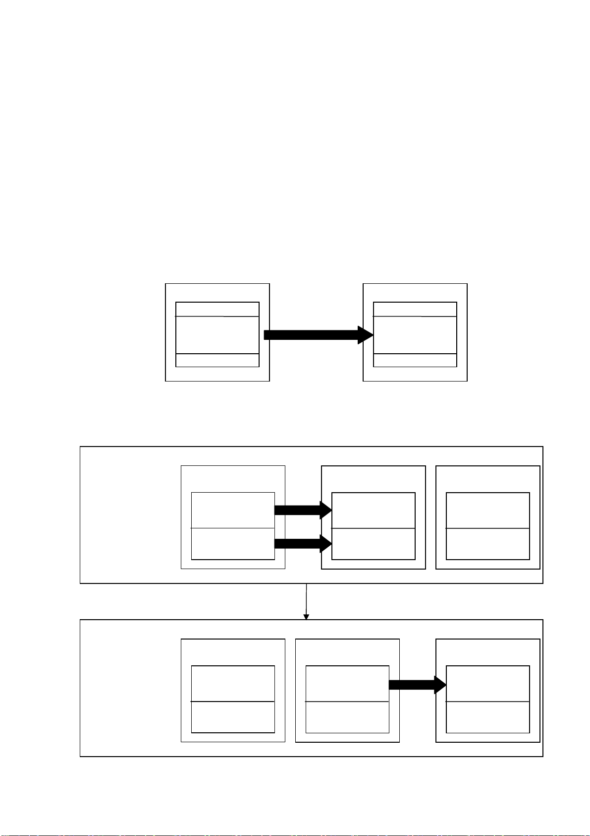
4.1.1 CPU Parameter Area and Master Module Parameter Memory ............................................... 4
4.1.2 Procedure for Parameter Settings to Data Link Startup with GX Developer............................ 4
4.2 Parameter Setting Items ................................................................................................................ 5
4.3 Example of Parameter Settings with GX Developer....................................................................... 6
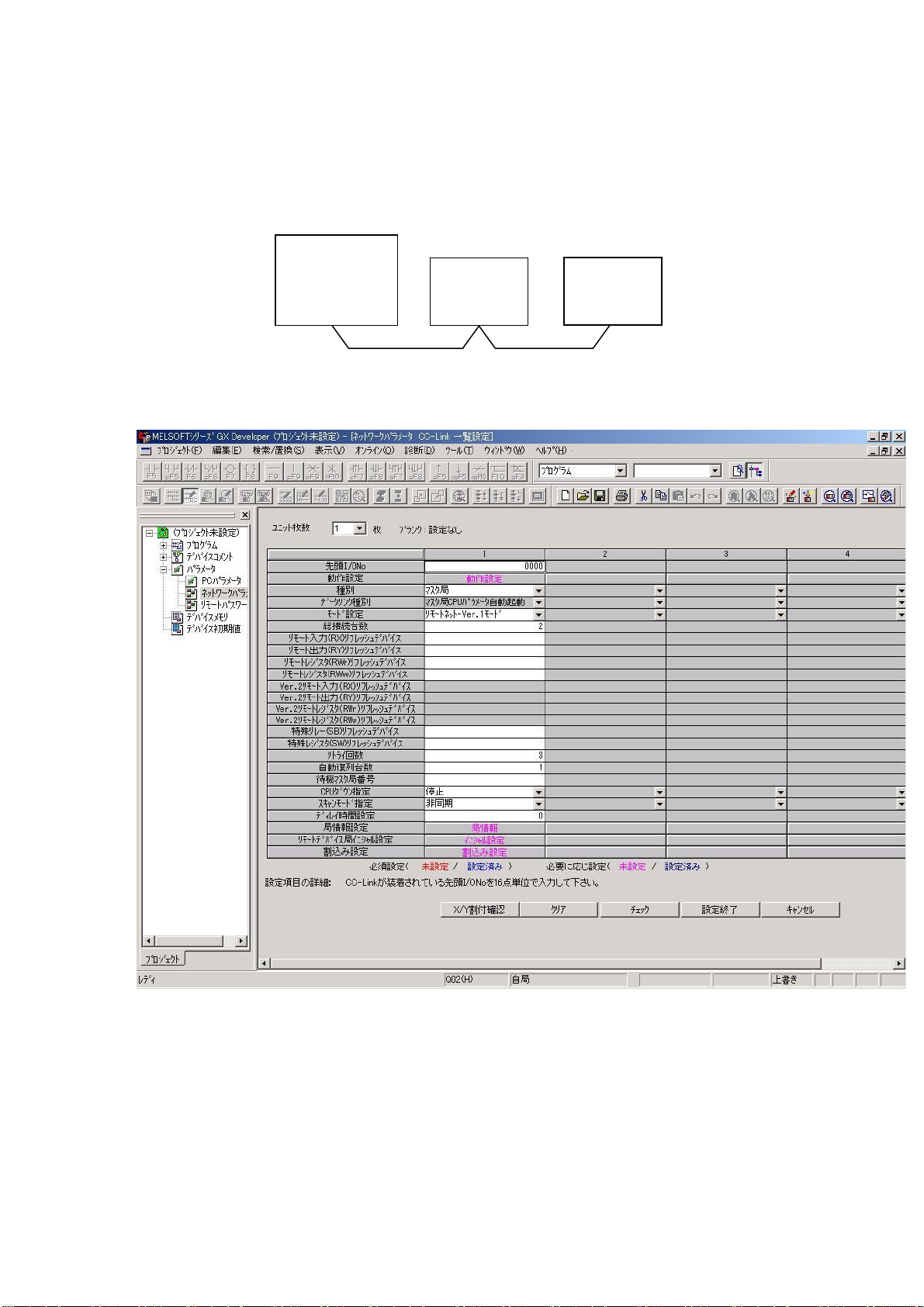
4.3.1 Master Station Network Parameter Settings ........................................................................... 6
4.3.2 Master Station Automatic Refresh Parameter Settings ......................................................... 10
5. Communication Between the Master Station and ME96NSR.............................................................. 12
5.1 Communication Guideline ............................................................................................................ 12
5.2 Initial Communication................................................................................................................... 13
5.3 Normal Communication................................................................................................................ 14
5.4 Error Communication ................................................................................................................... 14
6. Remote I/O and Remote Register ....................................................................................................... 15
6.1 Remote Input RX, Remote Output RY ......................................................................................... 15
6.1.1 Remote input RX................................................................................................................... 15
6.1.2 Remote Output RY................................................................................................................ 16
6.2 Remote Register (RWr, RWw)...................................................................................................... 17
6.2.1 Supported Command............................................................................................................ 17
6.2.2 Details of Commands............................................................................................................ 18
6.2.3 About Error Occurrence ........................................................................................................ 34
7. Abbreviations and Special Terms ........................................................................................................ 35
8. Program Example................................................................................................................................ 36
8.1 Program Content.......................................................................................................................... 36
8.2 System Configuration................................................................................................................... 36
8.3 Device Allocation.......................................................................................................................... 37
8.4 Parameter Settings ...................................................................................................................... 38
8.4.1 Network Parameter Settings and Auto Refresh Parameter Settings ..................................... 38
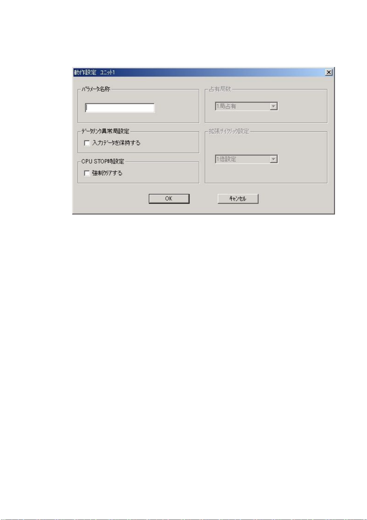
8.4.2 Operational Settings ............................................................................................................. 39
8.4.3 Station Information Settings .................................................................................................. 39
8.5 Program Example ........................................................................................................................ 40
9. Test Function Mode............................................................................................................................. 49
9.1 How to Test .................................................................................................................................. 49
9.2 Reply Data ................................................................................................................................... 49

1. General Description
This manual describes the programming methods that should be created by the user for monitoring
measurement value of the Electronic Multi-Measuring Instrument (called ME96NSR from here on) with the
PC CPU through Control & Communication Link (abbreviated as CC-Link from here on).
In programming, read the following related manuals in addition to this mannual.
Table 1.1 Related Manuals
Manual Name Manual No.
CC-Link System Master/Local Module User’s Manual
Type:QJ61BT11 SH(NA)-080016
CC-Link System Master/Local Module User’s Manual
Type:QJ61BT11N SH(NA)-080394
User’s Manual for ME96NSR Supplied with
product
2. Specification
ME96NSR specification is shown in Table 2.1.
Table 2.1 ME96NSR Specification
Item Specification
Station type Remote device station
Number of occupied stations 1 station
Maximum number of stations
per master station
42 stations ( In case of connecting only remote device
station occupied by 1 station.)
Transmission speed 156kbps/625kbps/2.5Mbps/5Mbps/10Mbps
RX, Ry 32 points each
RWw, RWr 4 points each
(2/n)
LEN080334
Master
station
ME96NSR ME96NSR ME96NSR
Maximum number of connection is 42.
(In case of ME96NSR connection.)
ME96NSRME96NSRME96NSR
System Configration (CC-Link)

3. Configuration Conditions of CC-Link System
A total of 64 remote I/O stations, remote device stations, or local stations can be connected for one master
station. Station type of ME96NSR is remote device station, and the number of occupied stations is 1
station.
However, the following conditions must be satisfied:
(1) { (1×a) + (2×b) + (3×c) + (4×d) } ≦64
a:Number of modules occupying 1 station (ME96NSR is applied.)
b:Number of modules occupying 2 stations
c:Number of modules occupying 3 stations
d:Number of modules occupying 4 stations
(2) { (16×A) + (54×B) + (88×C) } ≦2304
A:Number of remote I/O stations ≦64
B:Number of remote device stations (ME96NSR is applied.) ≦42
C:Number of local stations, standby master stations and intelligent device stations ≦26
ME96NSR
(3/n)
LEN080334

4. Parameter Settings
4.1 Procedure from Parameter Settings to Data Link Startup
The following explains the procedure from setting the parameters to stating the data link.
4.1.1 CPU Parameter Area and Master Module Parameter Memory
(1) CPU Parameter Area
This area is used to set the basic values for controlling the programmable controller system and the
network parameters that control the CC-Link system.
(2) Master Station Parameter Memory
This area stores the network parameters for the CC-Link system.
When the module is powered OFF or the programmable controller CPU is reset, the network
parameters are erased.
Programmable controller CPU Master station
4.1.2 Procedure for Parameter Settings to Data Link Startup with GX Developer
Follow the procedure below for parameter settings to data link startup:
GX Developer Master station
Network
parameters
Parameter memory
Programmable controller CPU
Network
parameters
CC-Link system
parameter area
Automatic refresh
parameters
Network
parameters
Automatic refresh
parameters
The GX Developer is
used to create
network parameters
and automatic refresh
parameters, which
are then written to the
programmable
controller CPU.
GX Developer Master station
Network
parameters
Parameter memory
Programmable controller CPU
Network
parameters
CC-Link system
parameter area
Automatic refresh
parameters
Network
parameters
Automatic refresh
parameters
When the
programmable controller
system is powered ON
or the programmable
controller CPU is reset,
the network parameters
in the programmable
controller CPU are
transferred to the master
station and the data link
is automatically started.
Power ON
CPU reset CC-Link system
network
parameter area
Parameter area
CC-Link system
network
parameter area
Parameter memory
(4/n)
LEN080334

(5/n)
LEN080334
4.2 Parameter Setting Items
The following lists the items to be stored in the master station parameter memory.
Setting item Description
Number of
connected
modules
Sets the total number of remote stations, local stations, intelligent device stations
and standby master station that are connected to the master station (including
reserved stations).
Default value : 64 (modules)
Setting range : 1 to 64 (modules)
Number of
retries
Sets the number of retries when a communication error occurs.
Default value : 3 (times)
Setting range : 1 to 7 (times)
Number of
automatic return
modules
Sets the total number of remote stations, local stations, intelligent device stations
and standby master stations that can be returned to system operation by a single
link scan.
Default value : 1 (module)
Setting range : 1 to 10 (modules)
Standby master
station
specification
Specifies the station number of the standby master station.
Default value : Blank (no standby master station specified)
Setting range : Blank, 1 to 64 (Blank: No standby master station specified)
Operation
specification
when CPU is
down
Specifies the data link status when a master station programmable controller CPU
error occurs.
Default value : Stop
Setting range : Stop, Continue
Scan mode
specification
Specifies either synchronous or asynchronous mode for sequence scan.
Default value : Asynchronous
Setting range : Asynchronous, Synchronous
Delay setting Sets 0 for the delay time.
Reserved
station
specification
Specifies the reserved station.
Default value : Not specified
Setting range : Not specified, Specified
Error invalid
station
specification
Specifies the error invaled station.
Default value : Not specified
Setting range : Not specified, Specified
Station
information
Sets the station information according to the connected remote station, local
station, intelligent device station, and standby master station.
Default value : Ver.1 remote I/O station, occupies 1 station,
Station number 1 to Ver.1 remote I/O station,
occupies 1 station, station number 64
Setting range station type : Remote I/O station, remote device station,
intelligent device station/Ver.1, Ver.2
(single, double, quadruple, octuple)
Number of occupied stations : 1 to 4
Station number : 1 to 64

4.3 Example of Parameter Settings with GX Developer
This section explains the parameter settings using the GX Developer. In the setting parameters used with
GX Developer, the setting of master station network parameters and the setting of automatic refresh
parameters are done. For more details on the GX Developer operation, refer to the GX Developer
Operating Manual.
The explanations in this section are based on the follwing example of the system configuration.
Master station
(X00 to X1F)
(Y00 to Y1F)
ME96NSR
(occupies
1 station)
ME96NSR
(occupies
1 station)
Station number 1 Station number 2
4.3.1 Master Station Network Parameter Settings
(1) The follwing describes an example of the parameter settings. See (2) for actual settings.
(2) Set the network parameters using the following procedure.
(a) Set the “No. of boards in module” for which the network parameters are to be set.
Default value : None
Setting range : 0~8 (Boards)
※Modules for the parameter setting with the G(P).RLPASET instruction should not be included in the
setting for “No. of boards in module”.
Example) Set 1 (Board).
(6/n)
LEN080334

(b) Set the “Start I/O No.” for the master station.
Default value : None
Setting range : 0000~0FE0
Example) Set 0000.
(c) Set the Parameter name in “Operational Settings.”
Even if the Parameter name is not set, this will not affect the operation of the CC-Link system.
Default value : None
Setting range : 8 characters or less
Example) Set “None“.
(d) Set the input status for the data link error station in “Operation settings”.
Default value : Clear (“Hold input data” not checked)
Setting range : Hold (“Hold input data” checked)
Clear (“Hold input data” not checked)
Example) Set to Clear (“Hold input data” not checked).
(e) Set the slave station refresh/compulsory clear setting at programmable controller CPU STOP in
“Operational settings”.
Default value : Refresh (“Clears compulsorily” not checked)
Setting range : Refresh (“Clears compulsorily” not checked)
Clears compulsorily (“Clears compulsorily” checked)
Example) Set to Refresh (“Clears compulsorily” not checked).
(f) Set the station type for “Type”.
Default value : Master station
Setting range : Master station, Mastar station(Duplex function), Local station, Standby master station
Example) Set the Master station.
(7/n)
LEN080334

(8/n)
LEN080334
(g) Set the CC-Link mode for “Mode”.
Default value : Remote net (Ver.1 mode)
Setting range : Remote net (Ver.1 mode), Remote net (Ver.2 mode), Remote net (Additional mode),
Remote I/O net mode, Off line
Example) Set to Remote net (Ver.1 mode).
(h) Set the total number of connected stations in the CC-Link system including reserved stations for
“All connect count”.
Default value : 64 (modules)
Setting range : 1 to 64 (modules)
Example) Set to 2 (modules).
(i) Set the number of retries for “Retry count”, when communication error occurs.
Default value : 3 (times)
Setting range : 1 to 7 (times)
Example) Set to 3 (times).
(j) Set the number of modules that can return to system operation by a single link scan for “Automatic
reconnection station count”.
Default value : 1 (module)
Setting range : 1 to 10 (modules)
Example) Set to 1 (module).
(k) Set the station number for the standby master station for “Standby master station No.”.
Default value : Blank (No standby master station specified)
Setting range : Blank, 1 to 64 (Blank: No standby master station specified)
Example) Set to Blank (No standby master station specified).
(l) Set the data link status for “PLC down select”, when a master station programmable controller CPU
error occurs.
Default value : Stop
Setting range : Stop, Continue
Example) Set to Stop.
(m) Set whether the link scan for the sequence scan is synchronous or asynchronous for “Scan mode
setting”.
Default value : Asynchronous
Setting range : Asynchronous, Synchronous
Example) Set to Asynchronous.
(n) Set 0 for the delay time.

(o) Set the station data for “Station information settings”.
Dafault value : Remote I/O station, single, Occupies 1 station, 32 points, or no setting for reserved
stations/error invalid.
Setting range : Station type - No setting
Remote I/O station
Remote device station
Intelligent device station
(including local staton and standby master station)
Expanded cyclic setting (cannot be changed) -
single
Number of occupied stations -
No setting
Occupies 1 station
Occupies 2 stations
Occupies 3 stations
Occupies 4 stations
Remote station points (cannot be changed) -
32 points [when occupies 1 station]
64 points [when occupies 2 station]
96 points [when occupies 3 station]
128 points [when occupies 4 station]
Reserved/invalid station select -
No setting
Reserved station
Invalid station (error invalid station)
Intelligent buffer select -
No setting
Send 0, 64 to 4096
Receive 0, 64 to 4096
Automatic 0, 128 to 4096
Example) Set the station data according to the system configuration specified in Section 4.3.
As ME96NSR is remote device station, and the number of occupied stations is 1
station, it becomes the following.
(9/n)
LEN080334

4.3.2 Master Station Automatic Refresh Parameter Settings
(1) The following shows an example of the parameter settings. See (2) for actual settings.
(2) Set the automatic refresh parameters using the following procedure.
(a) Set the remote input (RX) refresh device for “Remote input (RX)”.
Default value : None
Setting range : Device name – Select from X, M, L, B, D, W, R or ZR.
Device number – Within the range of the device points that the CPU has.
Example) Set to X100
(b) Set the remote output (RY) refresh device for “Remote output (RY)”.
Default value : None
Setting range : Device name – Select from Y, M, L, B, T, C, ST, D, W, R or ZR.
Device number – Within the range of the device points that the CPU has.
Example) Set to Y100.
(c) Set the remote register (RWr) refresh device for “Remote register (RWr)”.
Default value : None
Setting range : Device name – Select from M, L, B, D, W, R or ZR.
Device number – Within the range of the device points that the CPU has.
Example) Set to W300.
(10/n)
LEN080334

(11/n)
LEN080334
(d) Set the remote register (RWw) refresh device for “Remote register (RWw)”.
Default value : None
Setting range : Device name – Select from M, L, B, T, C, ST, D, W, R or ZR.
Device number – Within the range of the device points that the CPU has.
Example) Set to W400.
(e) Set the link special relay (SB) refresh device for “Special relay (SB)”.
Default value : None
Setting range : Device name – Select from M, L, B, D, W, R, SB or ZR.
Device number – Within the range of the device points that the CPU has.
Example) Set to SB0.
(f) Set the link special register (SW) refresh device for “Special register (SW)”.
Default value : None
Setting range : Device name – Select from M, L, B, D, W, R, SW or ZR.
Device number – Within the range of the device points that the CPU has.
Example) Set to SW0.
POINT
(1) For the automatic refresh parameter setting, set the start device only. Devices
are automatically assigned until the last station number including reserved
stations and occupied stations.
(2) When setting X, Y, B, W, SB and SW as refresh devices, make setting so that
they do not overlap with the device numbers used on the other networks, etc.

5. Communication Between the Master Station and ME96NSR
5.1 Communication Guideline
There are three communication statuses (Initial Communication, Normal Communication, Error
Communication) between the Master station and ME96NSR.
The following can be performed at normal communication.
・ Monitoring of the measurement values such as the current, voltage and energy, etc.
・ Monitoring of the bit data of the alarm state and the digital input state.
・ Setting the set data of the time constant for current demand.
ME96NSR has a special-purpose command for each measurement items and each setting items. It
becomes possible to monitor measurement value or to set the setting value by writing the command into
the remote register RWw of the master station.
(12/n)
LEN080334
Command/Data
Word device(Ex:W)
Command
execution request
Bit device(Ex:Y)
Command
completion reply
Bit device(Ex:X)
Reply data to
command
Word device(Ex:W)
PLC CPU
Command/Data
Remote register(RWw)
Remote output(RY)
Remote input(RX)
Reply data to
command
Remote register(RWr)
Master station
Command/Data
Remote register (RWw)
Remote input(RX)
Reply data to
command
ME96NSR
Command
execute
Link scan
Automatic refresh
①②
③④
⑥⑤
⑧⑦
① By automatic refresh, command and data stored in the word device of PLC CPU are stored in the “remote
register RWw”of the master station.
② By link scan, command and data stored in the “remote register RWw”of the master station are sent to
ME96NSR, and is stored in the “remote register RWw”of the ME96NSR.
③ By automatic refresh, command execution request stored in the bit device of PLC CPU is stored in the “remote
output RY”of the master station.
④ By link scan, command execution request stored in the “remote output RY”of the master station is sent to
ME96NSR, and is stored in the “remote output RY”of the ME96NSR. And then ME96NSR executes the
command and data.
⑤ By link scan, command completion reply stored in the “remote input RX”of the ME96NSR is sent to the master
station, and is stored in the “remote input RX”of the master station.
⑥ By automatic refresh, command completion reply stored in the “remote input RX”of the master station is stored
in the bit device of the PLC CPU.
⑦ By link scan, reply data to command stored in the “remote register RWr”of the ME96NSR is sent to the master
station, and is stored in the “remote register RWr”of the master station.
⑧ By automatic refresh, reply data to command stored in the “remote register RWr”of the master station is stored
in the word device of the PLC CPU.
Overview of the Command Communication to ME96NSR
Remote output(RY)
Command
execution request
Command
execution request
Command
completion reply
Command
completion reply
Remote register(RWr)

5.2 Initial Communication
Initial communication is performed at the beginning after the power supply is turned on or hardware is reset.
Refer to section 6.1 about the remote input RX and the remote output RY.
①
② ④
③
RX(n+1)8 ③
(Initial data processing request flag)
RY(n+1)8
(Initial data setting copletion flag)
RX(n+1)B
(Remote READY)
①After the power supply is turned on, or hardware is reset, the initial data processing request flag is turned on by
ME96NSR.
②After the initial data processing request flag is turned on, turn on the initial data setting completion flag.
③After the initial data setting completion flag is turned on, the initial data processing request flag is turned
off and the remote READY is turned on.
④After the initial data processing request flag is turned off, turned off the initial data setting completion flag.
(13/n)
LEN080334

5.3 Normal Communication
After initial data processing is complete, the normally communication is performed to monitor the
measurement values and to set the parameters.
Command and related data
Remote registe
r
(RWw)
RYnF
(Command execution request flag)
Reply data
①
RXnF
(Command completion reply flag)
Remote registe
r
(RWr)
③
④
⑤
②
①After writing the command and related data into the remote register RWw, turn on the command
execution request flag.
②After receiving the reply data corresponding to the command, the command completion reply flag turned
on.
Note: When sending commands successively, repeat ①to ⑤above.
The command can be sent only when the remote READY is ON.
④After reading the reply data, cancel the command execution request by turning off the command
execution request flag.
⑤After the command execution request flag is turned off, the command completion reply flag is turned off.
③After the command completion reply flag is turned on, read the reply data from the remote register RWw.
5.4 Error Communication
Error occurrence
(14/n)
LEN080334
Note: Refer to “6.2.3 About error occurrence” for error code.
⑤After the error reset request flag is turned off, the remote READY is turned on and normal
communication is resumed.
③After the error reset request flag is turned on, the error status flag is turned off.
④After the error status flag is turned off, turn off the error reset request flag.
②When the error status flag is turned on, read the error code from the remote register RWr. Eliminate the
cause of the error while referring to the red error code. When resuming communication with ME96NSR,
turn on the error reset request flag.
①When an error occurs in ME96NSR, error status flag is turned on and the remote READY is turned off.
RX(n+1)A
(Error status flag)
RY(n+1)A
(Error reset request flag)
②
②
④
③
⑤
Error code
RX(n+1)B
Remote READY
Remote registe
r
(RWr)
①
①

(15/n)
LEN080334
6. Remote I/O and Remote Register
6.1 Remote Input RX, Remote Output RY
The remote input RX and remote output RY are used to communicate for bit data between the master
station and ME96NSR.
6.1.1 Remote input RX
The allocation of the remote input RX of ME96NSR is shown in the table below.
Description
Device
No. Signal name OFF(0) ON(1)Note
RXn0 Digital input 1 (DI1) OFF ON
RXn1 Digital input 2 (DI2) OFF ON
RXn2 Digital input 3 (DI3) OFF ON
RXn3 Digital input 4 (DI4) OFF ON
RXn4 Unusable --
RXn5 Alarm (total) Non-Alarm state Alarm state Note 2
RXn6 Alarm of Demmand current Non-Alarm state Alarm state Note 2
RXn7 Unusable --
RXn8 Alarm of Voltage Non-Alarm state Alarm state Note 2
RXn9 Alarm of Current Non-Alarm state Alarm state Note 2
RXnA Alarm of Active power Non-Alarm state Alarm state Note 2
RXnB Alarm of Reactive power Non-Alarm state Alarm state Note 2
RXnC Alarm of Frequency Non-Alarm state Alarm state Note 2
RXnD Alarm of Power factor Non-Alarm state Alarm state Note 2
RXnE Alarm of T.H.D (Voltage) Non-Alarm state Alarm state Note 2
RXnF Command completion
reply flag No receiving of reply date Receiving of reply data Note 1, 4
RX(n+1)0 Unusable --
RX(n+1)1 Unusable --
RX(n+1)2 Unusable --
RX(n+1)3 Unusable --
RX(n+1)4 Unusable --
RX(n+1)5 Unusable --
RX(n+1)6 Unusable --
RX(n+1)7 Unusable --
RX(n+1)8 Initial data processing
request flag
Power OFF, remote READY
ON, or error status flag ON
Power supply is turned ON or
hardware reset Note 1
RX(n+1)9 Unusable --
RX(n+1)A Error status flag No error occurrence Error occurrence Note 1
RX(n+1)B Remote READY Command sending not
possible
Normally communication status
(Command sending possible) Note 1
RX(n+1)C Unusable --
RX(n+1)D Unusable --
RX(n+1)E Unusable --
RX(n+1)F Unusable --
n: it can be obtained by converting “(station number -1)×2” to hexadecimal.
Note 1: For the details, refer to “5.Communication Between the Master Station and ME96NSR”
Note 2: “ON(1)” shows the state where the upper limit or the lower limit is exceeded.
Note 3: The number of alarms which can monitor are 4 items set up at ME96NSR.
Note 4: Alarm of harmonics current cannot be shown by remote input RX.

(16/n)
LEN080334
6.1.2 Remote Output RY
The allocation of the remote output RY of ME96NSR is shown in the table below.
Description
Device
No. Signal name ON(1)→OFF(0)OFF(0)→ON(1)Note
RYn0 Unusable --
RYn1 Unusable --
RYn2 Unusable --
RYn3 Unusable --
RYn4 Unusable --
RYn5 Unusable --
RYn6 Unusable --
RYn7 Unusable --
RYn8 Unusable --
RYn9 Unusable --
RYnA Unusable --
RYnB Unusable --
RYnC Unusable --
RYnD Unusable --
RYnE Unusable --
RYnF Command execution
request flag Cancel command request Command request Note 1
RY(n+1)0 Unusable --
RY(n+1)1 Unusable --
RY(n+1)2 Unusable --
RY(n+1)3 Unusable --
RY(n+1)4 Unusable --
RY(n+1)5 Unusable --
RY(n+1)6 Unusable --
RY(n+1)7 Unusable --
RY(n+1)8 Initial data
setting completion flag
Cancel normal communication
request
Normal communication
request Note 1
RY(n+1)9 Unusable --
RY(n+1)A Error reset request flag Cancel error reset request Error reset request Note 1
RY(n+1)B Unusable --
RY(n+1)C Unusable --
RY(n+1)D Unusable --
RY(n+1)E Unusable --
RY(n+1)F Unusable --
n: it can be obtained by converting “(station number -1)×2” to hexadecimal.
Note 1: For the details, refet to “5.Communication Between the Master Station and ME96NSR”
Point
Do not read or write to unusable remote registers. If reading or writing is performed, the
functions of ME96NSR are not guaranteed.

(17/n)
LEN080334
6.2 Remote Register (RWr, RWw)
The remote register RWr and RWw are used to communicate word data between the master station and
ME96NSR. Because it occupiers 1 station, the remote registers RWr and RWw each have 4 words in
length.
ME96NSR has the special-purpose commands for each measurement items and setting items.It becomes
possible to monitor each measurement values or set each parameters by writing into the remote register
RWw of the master station command and the related data allocated to the item you want to monitor or set.
6.2.1 Supported Command
The commands supported by ME96NSR are listed in the table below. For the details of each commands,
refer to “6.2.2 Details of Commands“.
Table 6.1 Suppoted Commands
Command Name Descriprion Note page
1H Data Monitor For monitoring measurement 19
2H Data Set For setting measurement 31
Note) 1: The command can be sent only when the remote READY is ON.
2: The command execution request flag and command completion reply flag are used to send the
command and receive replay data. For details of each flag, refer to “5.3 Normal Communication”.
3: In case of monitoring the present value and its maximum continuously according to the renewal data
timing of ME96NSR, the maximum may be smaller than the present value.

6.2.2 Details of Commands
The details of the command and reply data supported by ME96NSR are described here.
How to view the details of each command described is the following page is shown below.
*1: It is described as 8 bits data by combining the unit No. (high 4 bits) and the command (low 4 bits).
For example, When the unit No. is 0H and the command is 1H, it becomes “01H”.
Command value Command name
b15 b8 b7 b0
n Channnel No. Group No.
n+1 Index number 00H
n+2 Low data
n+3 High data
Remote register RWrn(ME96NSR→PLC)Remote register RWwm(PLC→ME96NSR)
b15 b8 b7 b4 b3 b0
m Group No. Unit No. 1H
m+1 00H Channel No.
m+2 00H 00H
m+3 00H 00H
m, n: Address is allocated to the master module by the station number setting.
*1
Command
1H Data Monitor
・ The details of data written into the remote resister RWwm are shown in the table below.
・ After writing the command as shown below into the remote register RWwm, set the command execution
request flag to ON(1). When the command completion reply flag turned on, the specified item is reset.
Contents of the resister sent from the master
station to the remote device station (ME96NSR).
The command value should be stored in the 1st
byte of the resister to be transmitted.
Because the length of transmission data is fixed
to 4 words, 00H should be stored in areas in
which no data is contained.
Contents of the resister received by the
master station from the remote device station
(ME96NSR).
Because the length of receive data is fixed to
4 words, 00H is stored in areas in which no
reply data is contained.
Description
b7 b4 b3 b0
Command: data range ・・・ 0H~7H
Unit No.: data range ・・・ 0H~7H
0H and 1H are used in ME96NSR
(18/n)
LEN080334

(1) Data Monitor Command (1H)1) Data Monitor Command (1H)
m, n : Address is allocated to the master module by the station number setting.m, n : Address is allocated to the master module by the station number setting.
Note: ME96NSR can monitor the data of the measurement item which is not displayed.Note: ME96NSR can monitor the data of the measurement item which is not displayed.
b15 b8 b7 b0
n Channel No. Group No.
n+1 Index number 00H
n+2 Low data
n+3 High data
b15 b8 b7 b4 b3 b0
m Group No. Unit No. 1H
m+1 00H Channel No.
m+2 00H 00H
m+3 00H 00H
(※)0H and 1H is used in the unit No. of ME96NSR
Remote register RWwm(PLC→ME96NSR)Remote register RWrn(ME96NSR→PLC)
・ After writing the command as shown below into the remote register RWwm, set the command excution
request flag to ON(1). When the command completion reply frag is turned on, the item specified is reset.
・ The details of the data written into the remote resister RWwm are shown in the table Table 6.2 to Table 6.10.
・ The item can carry out monitor changes with phase and wiring types. (Refer to Table 6.2 to Table 6.4)
1H Data Monitor
(19/n)
LEN080334
This manual suits for next models
1
Table of contents
Other Mitsubishi Measuring Instrument manuals
Popular Measuring Instrument manuals by other brands

HP
HP 200AB Operating and servicing manual

RHINOMOTIVE
RHINOMOTIVE R2737 user manual

Tenmars
Tenmars TM-101 user manual

Brooks Instrument
Brooks Instrument Ar-Mite MT 3750 Installation and operation manual

Hanna Instruments
Hanna Instruments HI96750C instruction manual

RKC INSTRUMENT
RKC INSTRUMENT AE500 INITIAL SETTING MANUAL

Tenmars
Tenmars TM-508A user manual

Extech Instruments
Extech Instruments AN200 user manual

BRUEL & KJAER
BRUEL & KJAER 4294 instruction manual

Honeywell
Honeywell NOTIFIER AM-8200 installation manual

Right Weigh
Right Weigh 250 Series Installation & operation manual

ABB
ABB COMMANDER 1900 Series Programming guide