Mitsubishi FR-EPN User manual

MITSUBISHI
INVERTER
Instruction Manual
FR-EPN
Communications
Option Unit

ii
DeviceNet is a registered trademark of Open DeviceNet Vendor Association (ODVA).
DeviceNetManager is a trademark of Allen-Bradley Company, Inc.

iii
Warning symbols For you own safety, please pay special attention to
instructions containing the following symbol:
This warning symbol indicates the
presence of dangerous voltage. It
informs you of high voltage
conditions, situation and locations
that may cause death or serious
injury if you do not follow precautions.
NOTES inform you of situations or conditions which
will damage machinery or cause additional motor-
operation downtime if you do not take suggested
steps to correct or address such situations or
conditions.

iv
Thank you for choosing this option unit for the Mitsubishi FREQROL
transistorized frequency inverters. Please read this manual carefully before
using.
DeviceNet Communications Option Unit (FR-EPN)
This option allows the inverter to be connected to a network adhering to the
DeviceNet communications protocol. Some important features are
highlighted below.
Data rates of 125K baud, 250K baud, and 500K baud are selectable.
Up to 64 stations supported on a single network.
Ability to add or remove stations without disrupting network operation.
Network access to all inverter parameters, Start/Stop commands, and
monitor data.

v
Table of Contents
1. STRUCTURE 1
2. INSTALLATION 2
2.1. PRE-INSTALLATION CHECKS 2
2.2. INSTALLATION PROCEDURE 2
2.3. CONNECTION TO NETWORK 7
2.4. LED STATUS INDICATOR 7
3. GETTING STARTED 10
3.1. BAUD RATE 10
3.2. NET MODE AND PARAMETER SETUP 10
3.3. CONNECTION AND DISCONNECTION 11
4. OPERATION 12
4.1. OPERATION MODES 12
4.2. OPERATION MODE SELECTION 12
4.3. FUNCTIONS AVAILABLE IN OPERATION MODES 13
4.4. INPUT FROM DEVICENET TO INVERTER 13
4.5. OUTPUT FROM INVERTER TO DEVICENET 14
4.6. OPERATION ON ALARM OCCURRENCE 15
4.7. INVERTER RESET 16
5. FR-EPN SPECIFIC PARAMETERS 17
5.1. PR.118 17
5.2. OTHER OPTION-SPECIFIC PARAMETERS 18

vi
6. OBJECT MAP 20
6.1. IDENTITY OBJECT - CLASS 0X01 20
6.2. DEVICENET OBJECT - CLASS 0X03 21
6.3. I/O ASSEMBLIES OBJECT CLASS 04 21
6.4. DEVICENET CONNECTION OBJECT CLASS 0X05 22
6.5. MOTOR DATA OBJECT - CLASS 0X28 25
6.6. CONTROL SUPERVISOR - CLASS 0X29 26
6.7. AC DRIVE CLASS 0X2A 27
6.8. A200E EXTENDED CLASS 0X66 31
7. ELECTRONIC DATA SHEET 36
8. PARAMETERS 37
9. SPECIFICATIONS 48

STRUCTURE
- 1 -
1. STRUCTURE
FR-EPN
Node Address
SW2
x1
SW1
x10
MNS
193 mm.
44 mm.
V+
CAN+
SHLD
CAN-
V-
Connector
DeviceNet
Connector
Station
Number
Switches
Status LED
Mounting
Hole
(2 places)
25 mm.
v
Front View Right Side View

INSTALLATION
- 2 -
2. INSTALLATION
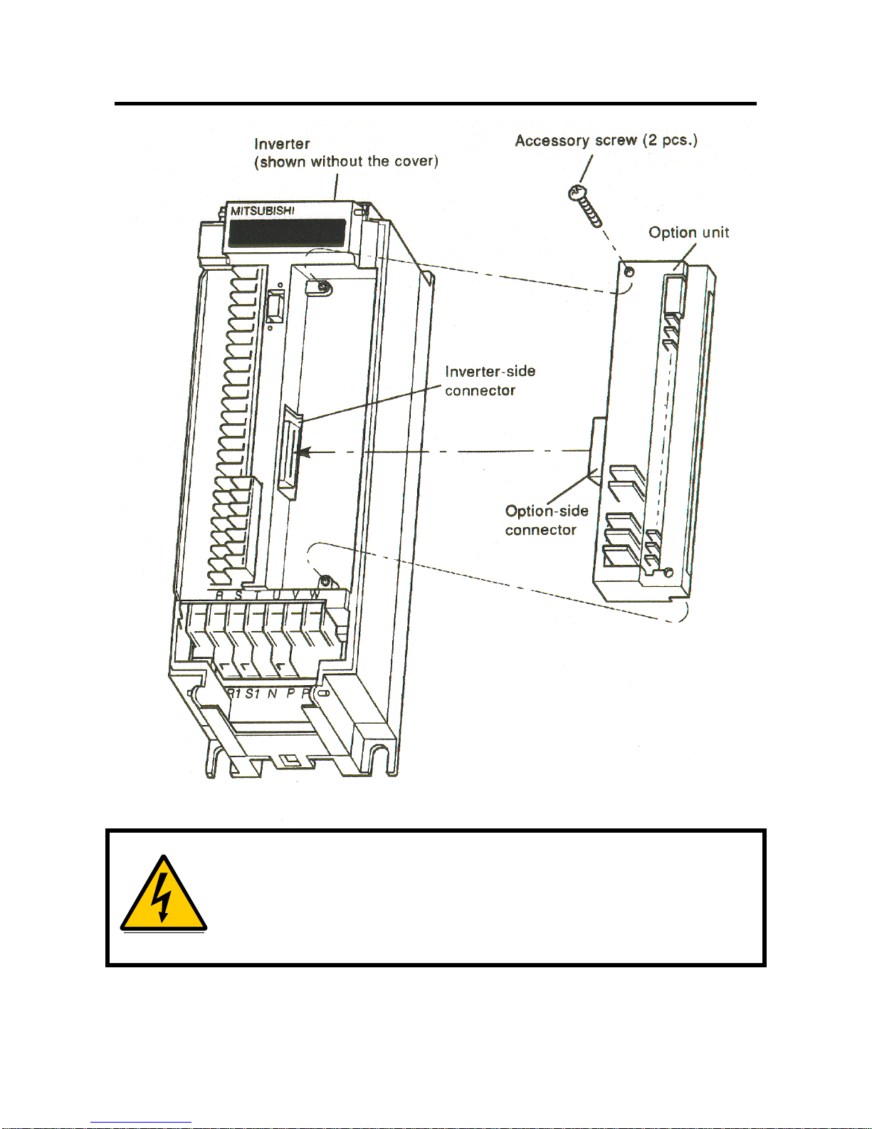
Remove the inverter cover and install the option unit using the following
procedure:
2.1. Pre-Installation Checks
(1) Check the inverter type.
This option unit may only be used with the FREQROL-A100E and A200E
series inverters and must not be used with any other series (e. g. A100,
A200, Z and F series). These models have a different option connector
to prevent connecting by mistake; however, if the user forces the
connector, the inverter may be damaged.
(2) Make sure that the inverter input power is off.
The inverter may be damaged if the option unit is installed with the input
power on. The inverter executes an initialization procedure at power on
that includes checking the option port. Adding the option later causes a
hardware conflict which may damage the inverter or option unit and
result in the alarm “E. CPU”.
(3) Ensure that the following accessories are supplied with the option unit:
Instruction Manual
Mounting Screws M3 x 14
2.2. Installation Procedure
(1) Snugly insert the connector of the option unit into the connector of the
inverter.
(2) Securely fix the option unit to the inverter at the top and bottom with the
mounting screws. If the screw holes in the option unit do not line up
with the inverter mounting holes, check that the connectors have been
fitted correctly.

- 3 -
Warning! Hazardous voltage present.
Always isolate the power from the inverter, and wait 5 minutes
to ensure the charge lamp has gone out before inserting or
removing this option unit, or touching the terminals.

INSTALLATION
- 4 -
(3) Make a drop cable out of DeviceNet thin cable long enough to extend
from the inverter to the network trunk cable. Remember that the
maximum length of this cable by the DeviceNet standard is 10 feet. On
one end of the cable, install a connector compatible with the trunk cable
and leave free wires on the other end. See figures below.
To FR-EPN
To Network Trunk
Cable
DeviceNet thin cable
DeviceNet Drop Cable with
Sealed Connector
1.5 in.
0.25 in.
Signal Wire
Signal Color
+V Red
CAN + White
Shield Orange
CAN - Blue
-V Black

- 5 -
IBM Compatible
Stub containing
terminating
resistor
Trunk Cable
Drop
Cable
(4) Strip the insulation and shielding on the free wire end of the drop cable
back about 1.5 inches to expose the four colored signal wires and the
silver shield wire. Strip the insulation on the signal wires back about 1/4
inch and tin the leads with solder. Tin the end of the shield wire also to
prevent it from fraying. Some pre-made cables have this step already
completed.
(5) Route the cable neatly through the wiring space along with any other
wires connected to inverter terminals so that when the front cover is
reinstalled, the cables to the inverter control circuit terminals and option
terminals are not caught between the inverter and inverter cover.
(6) Install the signal wires into the DeviceNet terminal block paying close
attention to match the colors of the wires with the colored label on the
cover. Insertion of a screwdriver into the upper holes of the terminal
block opens the clamps in the lower holes to allow wire insertion. A
flathead screwdriver of 3 mm maximum width works best. Removal of
the screwdriver then closes the clamps on the wire. These clamps grip
the wire very tightly and the user should not be able to pull the wires
back out if they are installed correctly .

INSTALLATION
- 6 -
Note: The correct method for opening the clamps on the DeviceNet
terminal block is simply to insert the screwdriver straight into
the unlocking hole. It does not involve inserting the
screwdriver and then using a lever action to open the clamps.
The increase in screwdriver thickness further up the shaft
opens the clamps as the screwdriver is inserted. Do not
attempt with an improperly sized screwdriver. See figure
below.
FR-EPN
Node Address
SW2
x1
SW1
x10
V+
CAN+
SHLD
CAN-
V-
RED
WHITE
GREY
BLUE
BLACK
DeviceNet
Cable
Wire Color
Wire terminal
Actuator
Insert driver into Actuator
to open Wire terminal

- 7 -
2.3. Connection To Network
(1) Upon completion of the installation procedure, the inverter should be at
rest with the power off. The option unit is mounted in the inverter with
the drop cable connected to the terminal block, but unconnected to the
network trunk cable. Set the node address on the two switches to a
number between 0 and 63. SW1 is the tens digit and SW2 is the ones
digit. Ensure that the number chosen is not already being used by
another station on the network including a master station. Any number
out of the range of 0 to 63 is changed to address 63 by the option unit
software.
Note: The state of the Node Address switches are sampled once at
power on. Changing the Node Address later on will have no
effect and the software will keep the number read at power on.
Turn power off, readjust the switches, and turn power back on
to change the node address.
(2) It is now safe to apply power to the inverter and run it in PU or external
mode provided that any external inverter control cables not associated
with DeviceNet are installed correctly. If the trunk connector is a
DeviceNet sanctioned pluggable or sealed connector, the connection to
the active network can be made at any time whether inverter power is
on or off. The option unit automatically detects when the connection is
made. If connecting to the network with free wires, power to the
network and inverter should be shut off as a safety measure in case two
or more signal wires are accidentally shorted together.
2.4. LED Status Indicator
(1) After connecting the drop cable to the trunk cable of the active network,
note the condition of the LED labeled MNS on the cover. The option
unit uses the Combined Module/Network Status LED scheme
proposed in the DeviceNet communications standard. The possible
states of this LED are as follows:

INSTALLATION
- 8 -
State of System LED
Condition Notes
Inverter power off
Network Power on Off Turn inverter power on. Option unit
will then complete duplicate station
number test
Network and inverter
power on.
Connection not yet
established by host
Flashing
Green The option unit has powered up
successfully and determined that its
station number does not conflict
with other stations. However, a host
has not yet established a
communication link.
Network and inverter
power on.
Connection
established by host
Green A master device on the network has
designated the option unit for
communication. LED holds this
state during communication also.
Connection Time-Out Flashing
Red Master designated option unit for
communication (LED Green state),
but then sent no messages within
the time limit set in the expected
packet rate. Check to see that host
station has not been disconnected
from the network.
Critical Link failure Red Failed communication device.
Duplicate station number
Network power off.
Cable from option unit to
network not connected or severed.
Option unit is only node on
network.
Network damaged.
Must cycle power to recover
from this fault
Note: When using complex software in the master, the rate of
connections and disconnections may be too fast for the user
to follow the network status in detail by simply watching the
LED.

- 9 -
(2) Match the condition of the LED with the table above. Most likely, it will
be flashing red or green depending on the software used in the master
station. Once a flashing green LED is achieved, the inverter is ready to
connect to its host and begin motor control operations through the
network.
(3) When inverter power is turned on with the option unit installed, the
option performs a diagnostic self test that can be viewed on the MNS
LED. This test is performed even if the option unit is not connected to
an active network. When power is turned on, the LED flashes green,
then red and finally turns off. The option unit then attempts its duplicate
station number test and will start flashing green within a few seconds if
successful. If unsuccessful, the LED will go solid red.
(4) At this point, your DeviceNet option unit should be installed and running
properly on your DeviceNet network. Replace the front cover on the
inverter paying attention not to cause excess strain on the internal
wiring. Your DeviceNet option is now installed. Please read through
the rest of this manual for information on the advanced features and
detailed operation of this option.

GETTING STARTED
- 10 -
3. GETTING STARTED
3.1. Baud Rate
The baud rate of the FR-EPN is set by the Baud Rate attribute of the
DeviceNet class, instance 1 (see section 6.2.3 Class 0x03 Instance
Attributes - Instance 1). This setting is also available in Pr.118 (see section
5.1 Pr.118). However, the best way to set it is using a configuration
program such as DeviceNetManager software.
To do this, the drive being configured should be set up as the only node on
the network aside from the master computer running DeviceNetManager.
Performing a parameter all-clear on the drive and cycling power will reset
the baud rate to 125 kbps. At this point, DeviceNetManager can be used to
configure the baud rate to any of the three possible speeds.
To change the speed manually via the parameter unit, refer to the
description of Pr.118.
3.2. Net Mode and Parameter Setup
(1) The inverter must be in Net Mode for motor control operations through
the network. Drive mode is controlled automatically by the FR-EPN
option card.
The FR-EPN will attempt to set the drive to Net Mode whenever a
DeviceNet connection is made. It will set the drive back to external
mode whenever all connections are released. If the drive is running at
these times, then the drive will not be set to Net mode, and control
cannot be performed via DeviceNet. Monitoring and reading, however,
can be performed regardless of the drive mode.
(2) Parameter 81, Motor Pole Count, defaults to four internally even though
9999 is displayed in the parameter unit. This parameter can be
modified via the network to control motors other than four pole motors.
An incorrect value for parameter 81 results in an incorrect motor speed.

- 11 -
3.3. Connection and Disconnection
(1) The FR-EPN option unit is considered a slave device in the DeviceNet
communications standard. This means that it cannot send messages
out on its own and dictate the operations of other devices on the
network. A master device establishes a connection to the option unit,
sends commands, requests for information, etc., and finally disconnects
when communication is completed. The purpose of connection and
disconnection is to prevent two master devices from sending motor
control commands to the same motor at the same time. It is possible
for one master to control the motor while another reads monitor data
and parameters.
(2) The option unit operates somewhat independently of the inverter in that
a master may connect or disconnect while the inverter is in PU mode.
However, motor control commands from the network will not be
recognized unless the connection is made while the inverter is in
external mode.
(3) When the master device disconnects from the option unit or the option
unit loses connection due to some fault such as a network power
failure, the inverter continues with the last command received until the
timeout value is reached. This is set in the expected packet rate of the
DeviceNet connection object. For example, the master might send a
command to start forward at 60 Hz and then disconnect. The MNS
LED will be green during communication and switch to flashing green
upon disconnection. The motor will run at 60 Hz until the timeout
occurs or the master establishes a new connection and sends different
commands.

OPERATION
- 12 -
4. OPERATION
Operation of the A200E changes slightly when the FR-EPN is installed, and
those changes are described here. Parameter definitions including newly
created parameters, as well as operation with the FR-EPN installed are
described.
4.1. Operation Modes
4.1.1. PU operation mode
Control of the inverter is from the parameter unit (PU).
4.1.2. External operation mode
Control of the inverter is by external signals connected to the inverter’s
terminal block.
4.1.3. Network (computer link) operation mode
Control of the inverter is via commands from a DeviceNet master.
However, FR-EPN-specific parameters 123 and 124 can be used to select
external control for forward/reverse/stop and output frequency setting.
4.2. Operation Mode Selection
The following table describes the required actions to change the operation
mode.
mode change required action
external operation
PU operation press PU key on parameter unit
PU operation
external operation press EXT key on parameter unit
external operation
network
operation DeviceNet connection is allocated
network operation
external
operation all DeviceNet connections are
released
The following conditions must also be met before a mode change can be
effected:
inverter is stopped
forward and reverse commands are off

- 13 -
Parameter 125 allows selection of network operation mode on power up
and after a drive reset.
4.3. Functions Available in Operation Modes
The functions of the drive depend on the mode of the drive. The following
table indicates the available commands according to the inverter operation
mode.
operation mode
control type command type net mode external
mode PU
mode
DeviceNet operation
command yes *1 no no
output frequency
setting yes *1 no no
monitor yes yes yes
parameter write yes (while
stopped ) *3 no *3 no *3
parameter read yes yes yes
inverter reset yes *2 no no
external
terminals operation
command yes *1 yes no
output frequency
setting yes *1 yes no
inverter reset yes yes yes
*1: depends on value of Pr.123 & 124
*2: inverter can’t be reset if computer link comm. error has occurred
*3: as set in Pr.77
4.4. Input from DeviceNet to Inverter
4.4.1. Operation Commands
FR-EPN supports STF and STR. Other operation command inputs are not
supported.

OPERATION
- 14 -
4.4.2. Output Frequency Setting
Output frequency setting is possible for the range 0 to 400 Hz in increments
of 0.01 Hz.
4.4.3. Inverter Reset
Inverter can be reset via DeviceNet using Identity object reset service.
Note that this reset service also performs a parameter clear, the type of
which depends on the type of the Identity reset service.
4.4.4. Parameter Writing
For parameter writing, all standard, special and hidden parameters are
supported. In addition, the parameters listed in the Option-specific
Parameter section of this specification are supported.
4.5. Output from Inverter to DeviceNet
4.5.1. Inverter Status
Inverter status can be monitored using class 0x2A, attribute 40, the A200E
Status. This is a bitmapped status byte defined as follows:
bit definition
0 running (RUN)
1 forward running
2 reverse running
3 up to frequency (SU)
4overload (OL)
5 instantaneous power failure (IPF)
6 frequency detection (FU)
7alarm
4.5.2. Inverter Monitoring
The following items can be monitored:
output frequency
output current
output voltage
running speed (RPM)
motor torque
Table of contents
Other Mitsubishi Network Hardware manuals