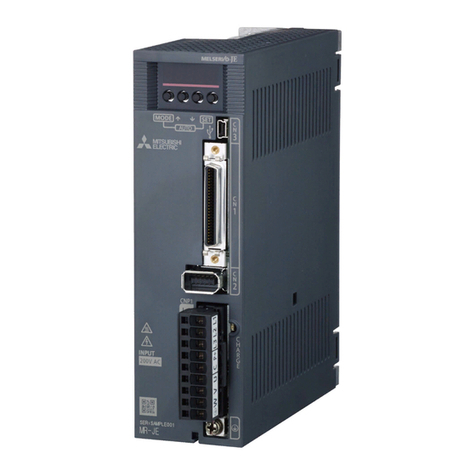
Mitsubishi MELSERVO-SO User manual

-~
ARTISAN
®
~I
TECHNOLOGY
GROUP
Your definitive source
for
quality
pre-owned
equipment.
Artisan Technology
Group
Full-service,
independent
repair
center
with
experienced
engineers
and
technicians
on staff.
We
buy
your
excess,
underutilized,
and
idle
equipment
along
with
credit
for
buybacks
and
trade-ins
.
Custom
engineering
so
your
equipment
works
exactly as
you
specify.
•
Critical
and
expedited
services
•
Leasing
/
Rentals/
Demos
• In
stock/
Ready-to-ship
•
!TAR-certified
secure
asset
solutions
Expert
team
ITrust
guarantee
I
100%
satisfaction
All
tr
ademarks,
br
a
nd
names, a
nd
br
a
nd
s a
pp
earing here
in
are
th
e property of
th
e
ir
r
es
pecti
ve
ow
ner
s.
Visit our website - Click HERE

MITSUBISHI
GENERAL-PURPOSE
AC
SERVO
SYSTEM
Position Control
MR-SO'II
P
-
Instruction
Manual
-

Thank you for youi purchase of MITSUBISHI [general-purpose
1
servo-sys tern tlMELSERVO.SOt'
.
This manual describes the installation. operation. mainte-
nance. troubleshooting and other important information neces-
sary for successful use of your MELSERVO-SO
.
For trouble.free. long use of your MELSERVO.SO. please read
this manual carefully
.
1
.
CHECK UPON UNPACKING
.....
1
2
.
TRANSFERENCE
.....
1
3
.
INSTALLATION
.....
1
3.1
Servo-amplifier and power unit
3.2 Servo-motor
4
.
WIRING
......
4
4.1 Main (power) circuit
4.2 Control circuit
4.3 Standard :cirirlg diagram
4.4 Input/output terminals
4.5 Connector pin arrangement
4.6 Encoder extension cable
4.7 Capacity
of
power supply unit
5
.
INITIAL
SETTINGS
....
18
6
.
OPERATION
....
23
6.1 Check to be accomplished before starting
operation
....
23
6.2 Initial operation
....
23
6.3 Safety against power failure
....
25
6.4 Indicator lamps
....
25
7
.
ADJUSTMENT
....
28'
8
.
MAINTENANCE
....
3i
8.1 Caution on inspection
8.2 Parts and devices to be checked
8.3 Consumable parts

1.
CHECK
UPON UNPACKING
'When you receive MELSERVO-SO, check
it
to identify.
(1)
See the nameplate to make sure the models of the servo-
amplifier and the servo-motor, and the output ratings
meet your order.
(2)
Check
all
components
if
they were not damaged during the
transport.
If
any damage
is
found, or any question arises, please address
to our service agency.
2.
TRANSFERENCE
The servo-amplifier, power unit and servo-motor should be
carefully handled when they are transferred and located.
During transfer, care should be exercised not to damage the
encoder installed on the servo-motor
....
DO
NOT
HOLD
THE
EN-
CODER
BY
HAND,
NOR
APPLY
A
ROPE
TO
THE
ENCODER WHEN
THE
SERVO-
MOTOR
IS LIFTED
OR
TRANSFERRED.
Encoder
0
3.
INSTALLATION
3.1
Servo-amplifier and power unit
1)
The servo-amplifier and power unit should be located to
a clean and dry place where they are not exposed to the
direct sunlight, moisture, dense dust and detrimental
gases.
Ambient conditions
Ambient temperature
Ambient humidity
Vibration
0 to 5S°C (to be free from icing)
Max. 90% (to be free from conden-
sation)
Max.
O.SG

go up excessively.
Oil
-
level
v-ring
Lip
-
Note
Model l~imension"h"
(mm)
:
(
)
is
applied to motor
equipped with brake.
2)
The motor should _notbe located, where
is
at
high tempera-
ture and high humidity.
If
it
is
likely that the motor
is
exposed to splashing
oil or water, a suitable cover should be installed and
the leads should be led downward so that oil or water does
not run into the motor along the leads.
Ambient conditions
3)
When the motor shaft
is
directly coupled with a machine
shaft,
it'
is
recommeded to use
a
"flexible coupling" .capa-
ble of offsetting alighnment error between the two shafts.
Ambient temperature
Ambient humidity
Vibration
>
should
4).
The motor should not be overhauled and the encod,
not be relocated.
0
to 40°c (to be free from icing)
20
to
80%RH
(to be free from con-
densation)
Max.
2G
If
any foreign sound erises during motor operation, con-
sult our service agency.
5)
The motor with magnetic
pmke
should not be used for
deceleration.
It
should be used for prevention of fall in case of
power failure or emergency stop.
6)
The shaft of motor with magnetic brake may cause
flux leakage.

tation cannot be reversed (the system differs from con-
ventional motor control systems and inverter-controlled
systems), by changing power phase sequence.
9)
The input power source circuit should be such that the
power source cannot be directly applied to the output
terminals
(U.
V.
W).
Although the servo-amplifier
is
protected from short-
circuiting between servo-amplifier output lines (term-
inals
U,
V
and
W)
by
the overcurrent preventive func-
tion, the system
is
not protected from ground fault or
any
leak trouble. Therefore, care should be exercis-
ed to prevent contact of any conductor with case or
other metallic part.
10)
A
grounding wire should be connected to the ground term-
1-
inal
(7)
without fail (see Fig.
1).
The grounding should be of "class
3"
(resistance to
ground: maximum 100~~)with grounding wire of 2mm2 in
size. The grounding wire should be
as
short
as
possi-
ble.
(1) Exclusive
(2)
Common
(3)
Common
grounding grounding grounding
line
....
line
....
line
..
.
BEST
GOOD
NOT
ACCEFTABLE

@
Wiring
Application
Control signal
1
ine
Motor encoder
cable (leads)
o The signal lines should be laid down away from (at
least 20cm) the power lines
at
voltage higher than
AC
Symbol
CN1
CN2
lOOV
.....
Do not place signal line and power line to-
Illustration
Amplifier side Machine
side
F=
A
pair of twisted wires
HONDA
(0.3mm2) shorter than
2m
MR-SOF
Amplifier side Encoder
A
pair of twisted wires
HONDA
Max. 30m long
is
possible
MR-20M when
an
extension cable
is
used.
gether in the same wire wav or duct).
o If signal line cannot be separated from power line pro-
perly, they should not be laid down in parallel with
each other.
@
Termination of shield wires
o The armor of each shield wire should be connected to
connector terminal
FG
of servo-amplifier
(SG
for encod-
er cable) at one end. The other end of the armor
should be kept open.
@
Surge killer
o Installation of surge killer
AC
relay,
AC
solenoid valve and
AC
magnetic brake
around
the servo-amplifier should be
equipped with
a
surge killer.
DC
relay and
DC
solenoid valve externally connected to
the servo-amplifier should be equipped with
a
diode
(its
withstand voltage should
be
4
times the drive vol-

4.3
standard
wiring diagram

Signal name
FWD
SROKE
END
REV
STROKE
END
ZERO
PULSE
CLEAR
CON
pin
N6.
47
46
4
5
49
LSP
LSN
OP
CR
Function/application
Forward run stroke end
limit
switch terminal
When the terminal
is
dis-
connected from terminal
VDG,
"FWD runt' pulse sig-
nal
is
interrupted and
motor stops. After that,
motor operation can be
reversed. With stroke end
limit
switch, LSP
-
VDG
should be closed for op-
eration.
Reverse run storke end
limit
switch terminal
When the terminal
is
dis-
connected from terminal
CTJG,
"REV
run" pulse sig-
nal
is
interrupted and
motor stops. After that,
motor can be be run for-
ward. With stroke end
limit
switch, LSN
-
VDG
should be closed for op-
eration.
Zero pulse output terminal
When detector
is
aT
prede~ermined
pctton
TI>&
ts
clcsed.
This signal
is
used for
home position return, etc.
(1
signal per revolution
of motor)
Clear signal terminal
When this terminal
is
con-
I/O
I
I
0
0

I
/O
I
I
AM-
1%
in-
put
Am-
log
,t,
PU~
Signal name
COMMON
FWD
PULSE
TRAIN
REV
PULSE
TRAIN
SPEED
COMMAND
(speed refer-
ence
)
MONITOR
DC
POWER SUPPLY
CON
-
pin
NO.
27,28,29,
30,31
13
12
11
10
4
3
44
9
Symbol'
VDG
PP
PG
NP
NG
VC
MO
.
+15V
Functionjapplication
Contact input signal com-
mon terminals. They are
not connected to the con-
trol circuit common line.
FWD
pulse train input sig-
nal terminal
Pulse train output from
pulse generator such
as
AD71
is
input.
FWD
pulse train input sig-
nal common terminal
REV
pulse train input sig-
nal terminal
REV pulse train input sig-
nal common terminal
Speed command sigca?. input
terminal
When signal
at
+10V
is
in-
put, the motor runs
at
the
rated speed (3000rpm) in
CCW
direction.
The input resistance
is
10
-12
KQ.
Either motor speed signal
or motor torque signal
is
output (internally selec-
table).
Max.
'IOV,
1mA
+15V
DC
power supply term-
inal

(2)
Power supply unit
Table
2
Power supply unit 1/0 terminals
*
Signal name
ENCODER
OUTPUT
(Open collector
type
1
COMMON
ENCODER
OUTPUT
SIGNAL
0
A
OB
02
OG
CON
pin
NO.
33
34
35
19, 20
p3E-l
Signal name
AC
POWER SUPPLY
DC
OUTPUT
CONTACT
OUTPUT
GROUND
Function/application
2000 pulses
.
per revolu-
tion of motor (selecta-
ble
)
can be output from
OA
and
OB.
When
OZ
is
used, one
pulse per revolution of
motor
is
output.
Fhase
of output from
OA
is
in advance of phase
of output from
OB
by
h/2
phase.
Open collector output
common terminals
This
is
connected to the
motor encoder.
Symbo
1
R,
S
P,
N
a,
c
1-
-
-
1
/O
0
-
Function/application
To be connected to commercial power
AClOOV
50/60Hz.
To be connected to servo-amplifier
input terminals P
znd
N.
Auxiliary contact output terminals
for external
NF,
used when protective
circuit
is
built up
To be connected to grounding line.

4.6
Encoder extension cable
The motor encoder has
a
cable of
lm
long (with a connector)
and can be immediately connected to the servo-amplifier.
If
the distance between the servo-motor and the servo-ampli-
fier is longer than
lm,
use
an
extension cable specified by
us.
Cable length Model
MR-SOCBLSM
Motor
cable (leads)
.
...
lm
long
4.7
Capacity of power supply unit
Make sure the capacity of the power supply unit is large
enough for
the
rated output of the servo-amplifier, or for
the total rated output of the servo-unplifiers (when two or
more servo-amplifiers are fed with one power supply unit).

(3)
Jumper pins
Jumper pins should be set in accordance with the table
shown below. For location of each jumper pin, refer to
Fig. 3
(8.3).
Table
3
Function Abbre-
viation Description Factory
setting
No.In-position
range magnifi-
cation
X8
range set by "IN-PI1 dial
is
magni-
fied
8
times.
When this pin
is
set, in-position
Yes.
W
High SPM gain When this pin
is
removed, gain dur-
I
ing operation increases.
When high
SPM
gain
is
required, re-
move the pin and set
"R-GN"
VR
(po-
I
tentiometer) properly.
--
Positioning
control loop
gain
=]<hey are set so that positioning Yes.
Yes.
GNB
Level clear
control gain
is
within a range from
25
to 50. Refer to
5(4).
No.
LCR
I
When this pin
is
set, residual
pulses in the deviation counter
is
set to zero (while "clear" signal
I
is
on). The pin
is
set when analog
I
speed reference signal
is
used.
SPMO
Monitor
This pin
is
set for use of speed
monitor function.
Output
is
210~/3000rpm.
Speed Yes.
Torque
r
--
This pin
is
set for use of torque
monitor function.
No.
Output
is
*9V/300%.
Speed amplifier
integral
cornpfi-
so;t*cn
time constant
Over-shoot can
Load
GD~
be minimized
for large load
Motor
GD
GD~
when pin
is
This pin
is
set for set properly.
No.
Load
GD~
Motor
GD~
>
5-

fo
:
Pulse frequency of speed reference signal
0:
Jumper pin set
X
:
Jumper pin not set
.
Ks
..
.
4
2
1.33
1
Jumper pin setting
-
-.
Relationship between Relationship between
Ks
VR
"P-GN" setting and
and
jumper pin setting
KPO
GN
A
X
X
0
0
Example of setting:
GNB
X
0
X
0
When "P-RATElf
is
set to "4", "P-GN" to "3",
and
both jump-
er pins
"GNA"
and
"Gr\TBtt
are set, the positioning control
loop gain
is,
When motor
is
operated
at-
3000rpm, the number of residual
pulses
is
as
follows:
pf
.-=
No
8000
fo
=
4
3000
=
IOOxlO3
PPS
P-RATE
60 60
Pf
:
Number of positioning feedback pulses
(8000
pulses)
N,
:
Motor speed (rprn)
E
=
100
x
lo3
=
2353
pulses
42.5
@
For application where positioning
is
repeated frequently
o Remove jumper pin "Kp".
o Set
VR
"R-GN"
to 0110 position and set "P-GNU and jump-
er pins
"GNA"
and
1tGN311.

6.
OPERATION
6.1
Check to be accomplished before stzrting operasion
After the completion of installation and wiring, perform
the following check:
(1)
Check the wiring again.
o Are the
DC
supply lines
P
and
N
wired properly?
o
Is
the motor phase sequence
(U:
red,
V:
white and
W:
black) correct?
o
Is
AC
power supply not connected to the servo amplifi-
er output?
(2)
Is
short-circuiting not caused by wire chip,
swarf
or
any other metal chip?
(3)
Are terminal screws and other screws not loose?
Tighten loose screw
if
found.
(4)
Is
any conductor or cable not tense excessivly?
(5)
Are the ~otcrand machine ready for operation?
(6)
Are jumper pins in the servo-amplifier set properly?
6.2
Initial operation
(1)
Normal operation
@
After m&ing sure ItSERVO
ONtt
signal
is
not given, turn
.on the power.
v]
lamp on the power unit and
ml
lapon the
servo-mplifier
will
light.
@
After making sure positioning command signal
is
not
input, turn on "SERVO
ONtt
signal.
ISON]
lamp
will
light and the motor
is
energized, but
held locked in the current position (servo lock condi-
tion).
Check that "INPtt lamp lights brilliantly. If the lamp

6.3
Safety against power failure
(1)
The input power circuit (power unit primary circuit)
should have
a
"holding functionu that prevents automatic
restart when the power
is
restored after power failure.
(2) For use of
a
motor equipped with magnetic brake,
start
signal must be turned on after the magnetic brake
is
re-
leased.
(3)
The magnetic brake
is
used for prevention of fall of
load. Therefore, use
it
only for braking
in
case of
power failure or emergency stop.
6.4
Indicator lamps
The servo-amplifier and the power unit have the indicator
lamps listed in Table
4.
To monitor operation of the servo-amplifier and the power,
or to trace back trouble to the cause, see these lamps.
For location of each lamp, see Fig. 2.
Table
4
Indicator lamps
Unit
Servo-
amplifier
Name
POWER
SERVO
ON
IN-POSI-
TION
Symbo
1
PWR
SON
I
NP
Description
Lights when the power
is
turned
on and the system
is
fed with
the power.
Lights when "SERVO
ON"
signal
is
given.
The lamp becomes brighter when
speed reference pulses are in-
put.
Lights when motion reaches the
in-position range, or when speed
reference pulses
is
reduced to
53
pulses. The lamp becomes
brighter when positioning
is
completed and residual pulses
are
f3
pulses.

'+
a
umarss
Q
Indicat
lamps
lOOY
?
QQ
.)
Power supply unit
PN'R
0
v
EEX
ntrol signal conntctor)
(b)
Servo
amplifier
VR
controls have
a
scale of 10 gradua-
tions (0,
l,
2
....
10).
Setting
is
I1O"
when
it
is
turned counter-
clockwise unti
it
stops, and "10" when
fully turned clockwise.
The dial shown to the left has a scale of
16 graduations (0,
1,
2
....
F).
Fig.
2
Unit panel front view

Note:
If
load inertia
is
too large and desired response
cannot be obtained by changing setting of
V-GN,
set P-GN to slightly larger gain and decrease setting
of P-GN.
Note: To check signal waveform, use an synchroscope placed
above the ground (insulated from the ground).
When checking, use care not to allow the synchroscope
probe to come into contact with
a
live part other than
check pin.
Name
Po$t
ion
control
ZERO
adjustment
GAIN
ad-
justment
during
operation
To check speed feedback signal, connect the synchro-
scope across check pins and
m.
Function and adjustment
>
Time
In normal operation, readjust-
ment of this
VR
is
not requir-
ed.
It
is
set so that "INP" lamp
becomes brightest when motor
is
in "servo lock" condition.
This adjustment can be made
when jumper pin
ltKp"
is
remov-
ed.
Positioning motion becomes
faster when
it
is
turned clock-
wise.
Note that excess setting may
cause hunting.
Standard setting: "3"
-
"5"
Sym-
bol
ZERO
R-GN
For location of each check pin, refer to Fig.
3
8tP.C.
Setting
at
shipment
"5"
"0"

8.
MAINTENANCE
Since the servo-amplifier
is
of solid state type, daily check
and maintenance
is
not required.
It
is,
however, recommended that
it
is
inspected at least
yearly
.
The brush-less servo-motor does not require periodic mainte-
nance.
8.1 Caution on inspection
To check the servo-amplifier under operation, measure vol-
tages and currents referring to the instruction described
under paragraph
9.2,
and using care to avoid electric shock
(refer to para.
9.1).
8.2
Parts and devices to be checked
@
See the servo-amplifier interior if dust
is
deposited
and remove the dust if found.
@
Check terminal screws on terminal blocks for looseness
and retighten loose screws if found.
@)
Check the parts and devices for condition (discoloration
due to heat, damage, brezkage of conductor, etc.
)
.
8.3 Consumable parts
The servo-mplifier uses the fuse shown in the following
list.
If
the fuse
is
blown out, replace
it
with the
listed one or equivalent (the servo-unplifier
is
furnished
with one spare fuse).
GTX
series, ASAHI,
is
also applicable.
Amplifier model
MR-SO53
P
MR-S0103P
MR-S0203P
MR-SO403 P
Rating
10A
15A
Fuse
MF60NRlOAS
MF60NR15AS
Manufacturer
TOY0 FUSE
CO.
,
LTD.

Function
.
-
?WM
control
sarrier
Zurrent feed-
~acksignal
Encoder out-
3ut
Encoder output
Voltage/wavef orm
-
-
-
-.
-
--
About 6Vp-p
1~p-p/Ratedcurrent
PUS
PV
and
PW
outputs are in the
following phase sequence when the
motor runs counter-clockwise.
PA,
PB
and PZ outputs are in the
following phase sequence when the
motor runs counter-clockwise.
PA
and PB outputs are 2000p/revs
and at lOOkHz when the motor runs
at
3000rpm.
PZ
output
is
lp/revs SVo-p.
CON
1
-.
Without
Without
Ji
thout
ii
thout
Table of contents
Other Mitsubishi Servo Drive manuals