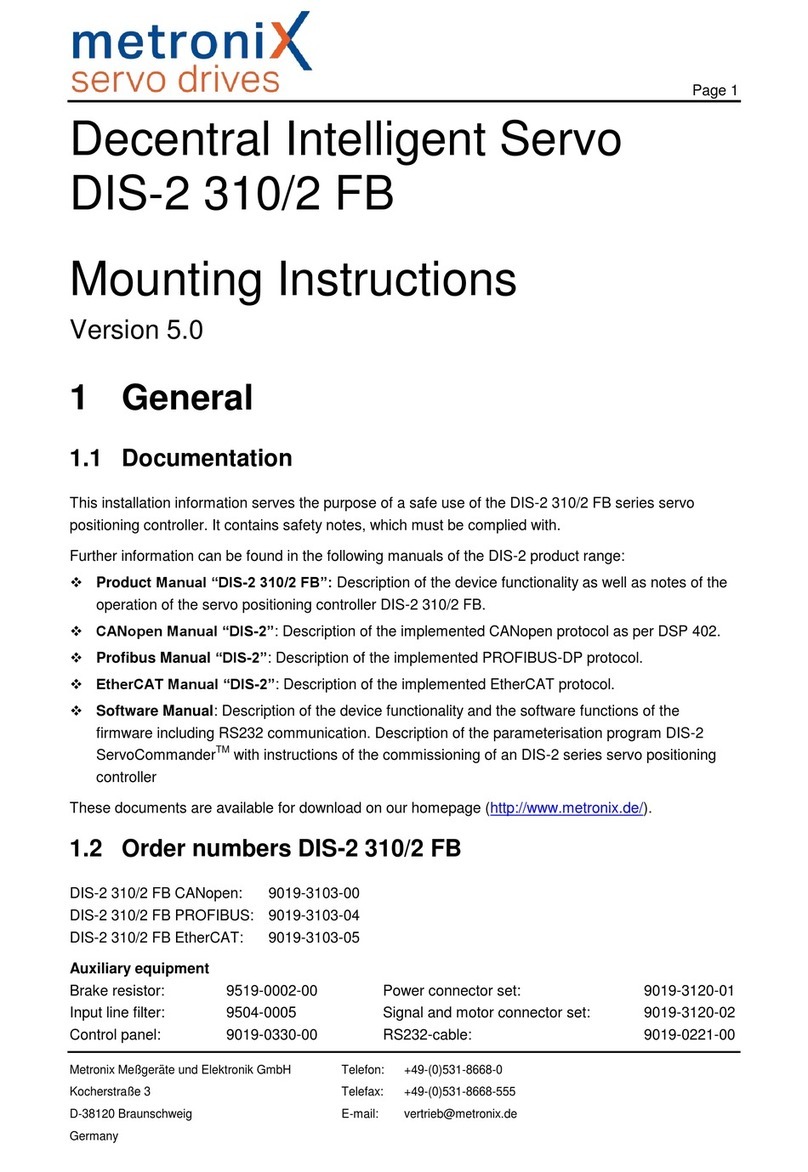
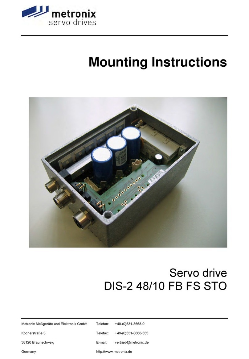
Metronix DIS-2 48/10 FB FS STO User manual

Metronix Meßgeräte und Elektronik GmbH Telefon: +49-(0)531-8668-0
Kocherstraße 3 Telefax: +49-(0)531-8668-555
Germany
Decentral Intelligent Servo
DIS-2 48/10
DIS-2 48/10 IC
DIS-2 48/10 FB
Mounting Instructions
Version 3.0
1 General
1.1 Documentation
This installation information serves the purpose of a safe use of the DIS-2 series servo positioning
controller. It contains safety notes, which must be complied with.
Further information can be found in the following manuals of the DIS-2 product range:
User Manual “DIS-2 48/10, DIS-2 48/10 IC, DIS-2 48/10 FB”: Description of the device
functionality as well as notes of the operation of the DIS-2.
Further on the description of the software functions of the firmware including RS232
communication. Description of the parameterisation program DIS-2 ServoCommander with
instructions on the commissioning of an DIS-2 series servo positioning controller
CANopen Manual “ Decentral Intelligent Servo DIS-2 48/10”: Description of the implemented
CANopen protocol as per DSP402.

Safety notes for electrical drives and controllers Page 2
2 Safety notes for electrical drives
and controllers
2.1 Used symbols
Information
Important information and notes.
Caution!
Non observance may result in severe property damages.
DANGER!
Non observance may result in property damages and in personal injuries.
Caution! Dangerous voltages.
The safety note indicates a possible perilous voltage.
2.2 General notes
In case of damage resulting from non-compliance with the safety notes in this manual, Metronix
Meßgeräte und Elektronik GmbH will not assume any liability.
Sound and safe operation of the servo drive controller requires proper and professional transportation,
storage, assembly and installation as well as proper operation and maintenance. Only trained and
qualified personnel may handle electrical devices:
TRAINED AND QUALIFIED PERSONNEL
in the sense of this product manual or the safety notes on the product itself are persons who are
sufficiently familiar with the setup, assembly, commissioning and operation of the product as well as
all warnings and precautions as per the instructions in this manual and who are sufficiently qualified in
their field of expertise:
Education and instruction or authorisation to switch devices/systems on and off and to ground
them as per the standards of safety engineering and to efficiently label them as per the job
demands.
Education and instruction as per the standards of safety engineering regarding the maintenance
and use of adequate safety equipment.
First aid training.
The following notes must be read prior to the initial operation of the system to prevent personal
injuries and/or property damages:
These safety notes must be complied with at all times.
Do not try to install or commission the servo drive controller before carefully reading all safety
notes for electrical drives and controllers contained in this document. These safety instruct-
ions and all other user notes must be read prior to any work with the servo drive controller.

Safety notes for electrical drives and controllers Page 3
In case you do not have any user notes for the servo drive controller, please contact your
sales representative. Immediately demand these documents to be sent to the person
responsible for the safe operation of the servo drive controller.
If you sell, rent and/or otherwise make this device available to others, these safety notes
must also be included.
The user must not open the servo drive controller for safety and warranty reasons.
Professional control process design is a prerequisite for sound functioning of the servo drive
controller!
DANGER!
Inappropriate handling of the servo drive controller and non-compliance of the
warnings as well as inappropriate intervention in the safety features may result in
property damage, personal injuries, electric shock or in extreme cases even death.
2.3 Danger resulting from misuse
DANGER!
High load currents may cause high electrical voltage (even if supply is ≤48 VDC)!
Danger to life or serious personal injury from electrical shock!
DANGER!
High electrical voltage caused by wrong connections!
Danger to life or serious personal injury from electrical shock!
DANGER!
Surfaces of device housing may be hot!
Risk of injury! Risk of burning!
DANGER!
Dangerous movements!
Danger to life, serious personal injury or property damage due to unintentional
movements of the motors!

Safety notes for electrical drives and controllers Page 4
2.4 Safety notes
2.4.1 General safety notes
The servo drive controller corresponds to IP54 class of protection as well as pollution level 1.
Make sure that the environment corresponds to this class of protection and pollution level.
Only use replacements parts and accessories approved by the manufacturer.
The devices must be connected to the supply as per EN regulations, so that they can be cut
off the mains supply by means of corresponding separation devices (e.g. main switch,
contactor, power switch).
Gold contacts or contacts with a high contact pressure should be used to switch the control
contacts.
Preventive interference rejection measures should be taken for control panels, such as
connecting contactors and relays using RC elements or diodes.
The safety rules and regulations of the country in which the device will be operated must be
complied with.
The environment conditions defined in the product documentation must be kept. Safety-
critical applications are not allowed, unless specifically approved by the manufacturer.
The compliance with the limits required by national regulations is the responsibility of the
manufacturer of the machine or system.
The technical data and the connection and installation conditions for the servo drive controller
are to be found in this product manual and must be met.
DANGER!
The general setup and safety regulations for work on power installations (e.g. DIN, VDE,
EN, IEC or other national and international regulations) must be complied with.
Non-compliance may result in death, personal injury or serious property damages.
Without claiming completeness, the following regulations and others apply:
VDE 0100 Regulations for the installation of high voltage (up to 1000 V) devices
EN 60204 Electrical equipment of machines
EN 50178 Electronic equipment for use in power installations
2.4.2 Safety notes for assembly and maintenance
The appropriate DIN, VDE, EN and IEC regulations as well as all national and local safety regulations
and rules for the prevention of accidents apply for the assembly and maintenance of the system. The
plant engineer or the operator is responsible for compliance with these regulations:
The servo drive controller must only be operated, maintained and/or repaired by personnel
trained and qualified for working on or with electrical devices.

Safety notes for electrical drives and controllers Page 5
Prevention of accidents, injuries and/or damages:
Additionally secure vertical axes against any kind of dangerous movements after the motor
has been switched off, e.g. by means of:
Mechanical locking of the vertical axle,
External braking, catching or clamping devices or
Sufficient balancing of the axle.
The motor holding brake supplied the whole time or an external motor holding brake driven
by the drive controller alone is not suitable for personal protection!
Render the electrical equipment voltage-free using the main switch and protect it from being
switched on again until the DC bus circuit is discharged, in the case of:
Maintenance and repair work
Cleaning
long machine shutdowns
Prior to carrying out maintenance work make sure that the power supply has been turned off,
locked and the DC bus circuit is discharged.
Be careful during the assembly. During the assembly and also later during operation of the
drive, make sure to prevent drill chips, metal dust or assembly parts (screws, nuts, cable
sections) from falling into the device.
Also make sure that the external power supply of the controller (24V) is switched off.
The DC bus circuit or the mains supply must always be switched off prior to switching off the
24V controller supply.
Carry out work in the machine area only, if AC and/or DC supplies are switched off. Switched
off output stages or controller enablings are no suitable means of locking. In the case of a
malfunction the drive may accidentally be put into action.
Initial operation must be carried out with idle motors, to prevent mechanical damages e.g.
due to the wrong direction of rotation.
Electronic devices are never fail-safe. It is the user’s responsibility, in the case an electrical
device fails, to make sure the system is transferred into a secure state.
The servo drive controller and in particular the brake resistor, externally or internally, can
assume high temperatures, which may cause serious burns.

Safety notes for electrical drives and controllers Page 6
2.4.3 Protection against contact with electrical parts
This section only concerns devices and drive components carrying voltages exceeding 50 V. Contact
with parts carrying voltages of more than 50 V can be dangerous for people and may cause electrical
shock. During operation of electrical devices some parts of these devices will inevitably carry
dangerous voltages.
DANGER!
High electrical voltage!
Danger to life, danger due to electrical shock or serious personal injury!
The appropriate DIN, VDE, EN and IEC regulations as well as all national and local safety regulations
and rules for the prevention of accidents apply for the assembly and maintenance of the system. The
plant engineer or the operator is responsible for compliance with these regulations:
Before switching on the device, install the appropriate covers and protections against
accidental contact. Rack-mounted devices must be protected against accidental contact by
means of a housing, e.g. a switch cabinet. The regulations VGB4 must be complied with!
Always connect the ground conductor of the electrical equipment and devices securely to the
mains supply. Due to the integrated line filter the leakage current exceeds 3.5 mA!
Comply with the minimum copper cross-section for the ground conductor over its entire
length as per EN60617!
Prior to the initial operation, even for short measuring or testing purposes, always connect the
ground conductor of all electrical devices as per the terminal diagram or connect it to the
ground wire. Otherwise the housing may carry high voltages which can cause electrical
shock.
Do not touch electrical connections of the components when switched on.
Prior to accessing electrical parts carrying voltages exceeding 50 Volts, disconnect the
device from the mains or power supply. Protect it from being switched on again.
For the installation the amount of DC bus voltage must be considered, particularly regarding
insulation and protective measures. Ensure proper grounding, wire dimensioning and
corresponding short-circuit protection.
The device comprises a rapid discharge circuit for the DC bus as per EN60204 section 6.2.4.
In certain device constellations, however, mostly in the case of parallel connection of several
servo drive controllers in the DC bus or in the case of an unconnected brake resistor, this
rapid discharge may be rendered ineffective. The servo drive controllers can carry voltage
until up to 5 minutes after being switched off (residual capacitor charge).

Safety notes for electrical drives and controllers Page 7
2.4.4 Protection against electrical shock by means of protective extra-low
voltage (PELV)
All connections and terminals with voltages between 5 and 50 Volts at the servo drive controller are
protective extra-low voltage, which are designed safe from contact in correspondence with the
following standards:
International: IEC 60364-4-41
European countries within the EU: EN 50178/1998, section 5.2.8.1.
DANGER!
High electrical voltages due to wrong connections!
Danger to life, risk of injury due to electrical shock!
Only devices and electrical components and wires with a protective extra low voltage (PELV) may be
connected to connectors and terminals with voltages between 0 to 50 Volts.
Only connect voltages and circuits with protection against dangerous voltages. Such protection may
be achieved by means of isolation transformers, safe optocouplers or battery operation.
2.4.5 Protection against dangerous movements
Dangerous movements can be caused by faulty control of connected motors, for different reasons:
Improper or faulty wiring or cabling
Error in handling of components
Error in sensor or transducer
Defective or non-EMC-compliant components
Error in software in superordinated control system
These errors can occur directly after switching on the device or after an indeterminate time of
operation.
The monitors in the drive components for the most part rule out malfunctions in the connected drives.
In view of personal protection, particularly the danger of personal injury and/or property damage, this
may not be relied on exclusively. Until the built-in monitors come into effect, faulty drive movements
must be taken into account; their magnitude depends on the type of control and on the operating
state.
DANGER!
Dangerous movements!
Danger to life, risk of injury, serious personal injuries or property damage!
For the reasons mentioned above, personal protection must be ensured by means of monitoring or
superordinated measures on the device. These are installed in accordance with the specific data of
the system and a danger and error analysis by the manufacturer. The safety regulations applying to
the system are also to be taken into consideration. Random movements or other malfunctions may be
caused by switching the safety installations off, by bypassing them or by not activating them.

Safety notes for electrical drives and controllers Page 8
2.4.6 Protection against contact with hot parts
DANGER!
Housing surfaces may be hot!
Risk of injury! Risk of burning!
Do not touch housing surfaces in the vicinity of heat sources! Danger of burning!
Before accessing devices let them cool down for 10 minutes after switching them off.
Touching hot parts of the equipment such as the housing, which contain heat sinks and
resistors, may cause burns!
2.4.7 Protection during handling and assembly
Handling and assembly of certain parts and components in an unsuitable manner may under adverse
conditions cause injuries.
DANGER!
Risk of injury due to improper handling!
Personal injury due to pinching, shearing, cutting, crushing!
The following general safety notes apply:
Comply with the general setup and safety regulations on handling and assembly.
Use suitable assembly and transportation devices.
Prevent incarcerations and contusions by means of suitable protective measures.
Use suitable tools only. If specified, use special tools.
Use lifting devices and tools appropriately.
If necessary, use suitable protective equipment (e.g. goggles, protective footwear, protective
gloves).
Do not stand underneath hanging loads.
Remove leaking liquids on the floor immediately to prevent slipping.

Technical data Page 9
3 Technical data
Range DIS-2 48/10
Ambient conditions and qualification:
Admissible temperature ranges Storage temperature: -25°C to +70°C
Operating temperature: 0°C to +50°C
up to 70°C with a de-rating of 2%/°C
Admissible installation height Up to 1000 m above msl, 1000 to 4000 m above msl at reduced power
Humidity Relative humidity up to 90%, not bedewing
Protection class IP54, dependent on mounting IP67 may be achieved
Pollution degree 1
CE conformity
Low-voltage directive:
EMC regulation::
Not applicable
EN 61 800 – 3
Dimensions and weight:
Dimensions: H*W*D 65*90*110 mm
Weight approx. 500 g
Performance data Power Supply [X1]:
DC supply Power Stage 0 V... 60 V DC (48 V DC nominal / 10 A nominal)
external Fuse 10 A / short circuit protection needed !
24 V logic supply
24 V DC [± 20%] / 0,20 A 1)
internal protected with poly-switch, triggered at approx. 1 A
1) plus supply current of the optional holding brake and driven I/Os
Brake Chopper
(only DIS-2 48/10 FB) Brake Chopper is integrated; UChop ≈60 V
external braking resistor with 4.7 Ω/ 100 W recommended
Motor connection specifications [X301 to X303]:
Specifications for operation with 48 V DC / THousing,max = 50°C
Output power 500 VA
Max. output power for 2 s 1500 VA
Output current 15 ARMS @ TPowerStage ≤50°C
10 ARMS @ TPowerStage ≤70°C
Max. output current for 2 s 40 ARMS @ TPowerStage ≤50°C
32 ARMS @ TPowerStage ≤70°C
PWM frequency 10 kHz / 20 kHz

Technical data Page 10
Resolver evaluation [X2]:
Suitable Resolver Industry standard, single speed,
exciting frequency 10 kHz, transfer ration ü = 1 : 0.5
Resolution > 12 Bit ( typ. 15 Bit)
Delay time signal detection < 200 µs
Speed resolution ca. 4 min-1
Absolute accuracy of angle
detection < 10´
Max. rotational speed 16.000 min-1
Evaluation of analogue Hall sensor signals [X2]:
Suitable Hall sensors HAL400 (Micronas), SS495A (Honeywell) and others
Output type: differential analogue output, VCM = 2.0 V...3.0 V
Signal amplitude: max. 4,8 Vss differential 1)
Resolution > 12 Bit ( typ. 15 Bit)
Delay time signal detection < 200 µs
Speed resolution ca. 10 min-1
Absolute accuracy of angle
detection < 30´
Max. rotational speed 16.000 min-1
1) Other Signal levels on request as custom specific version, please contact your local supplier.
Evaluation of Hiperface Encoders [X2]:
Suitable Encoder Stegmann Hiperface SCS / SCM60 ; SRS / SRM50 ; SKS36
other types – please contact supplier
Resolution Up to 16 Bit ( depends on number of increments)
Delay time signal detection < 200 µs
Speed resolution ca. 4 min-1
Absolute accuracy of angle
detection < 5´
Max. rotational speed 6.000 min-1
Evaluation of Six-Step-Sensors (Hall) and block commutation mode [X2]:
Suitable Six-Step-Sensors HALL-Sensors with +5 V supply; 120 ° phase shift between phases;
open collector or push-pull output; iout > 5 mA;
Resolution 6 steps per electric turn
Delay time signal detection < 200 µs
Speed resolution Depends on number of poles of the motor
Max. rotational speed 3.000 min-1 with a 4 pole motor

Technical data Page 11
Evaluation of Optical Encoders [X2]: supported only by DIS-2 48/10 FB !
Suitable encoder pulse counts Programmable 32 to 1024 periods per turn
Input signal level 5 V differential inputs / RS422-standard
Power supply for encoder +5 V / 100 mA max.
Input impedance Ri≈1600 Ω
Max. input frequency fmax > 100 kHz (pulses/s)
Motor temperature monitoring:
Digital Sensor Normally closed contact: Rcold < 500 ΩR
hot > 100 kΩ
Analogue Sensor Silicon temperature sensors KTY series
KTY81-2x0; KTY82-2x0 R25 ≈2000 Ω
KTY81-1x0; KTY81-2x0 R25 ≈1000 Ω
KTY83-1xx R25 ≈1000 Ω
KTY84-1xx R100 ≈1000 Ω
Digital inputs and outputs [X1]:
Logic inputs general 24V (8V...30V) active high, conforming with EN 1131-2
DIN0
DIN1
DIN2
DIN3
Bit 0 \
Bit 1, \ Target selection for positioning
Bit 2, / 16 targets selectable from target table
Bit 3 /
DIN4
Bit 4 \ Target Group selection
\ Target selection for positioning
/ 4 target groups with separate positioning parameters
Bit 5 / (speed, acceleration, positioning mode e.g.) selectable
DIN5
DIN6 Control signal Start positioning
DIN7 End switch input 0
DIN8 End switch input 1
DIN9 Controller enable at High, clear error high-low transition at Low
Logic outputs general 24V (8V...30V) active high, short circuit rated to GND
DOUT0 Operational state / Ready 24 V, max. 20 mA
DOUT1 Freely configurable, usable as
Encoder output A-Signal
(Pin shared with DIN2 and AIN1)
24 V, max. 20 mA
DOUT2 Freely configurable, usable as
Encoder output B-Signal
(Pin shared with DIN2 and AIN1)
24 V, max. 20 mA
DOUT3 (on X3) Holding brake 24 V, max. 700 mA

Mechanical installation Page 12
Incremental encoder output [X1] (DOUT1, DOUT2):
Number of lines Programmable 32 / 64 / 128 / 256 / 512 / 1024 lines / turn
Connection level 24 V single ended / maximum 20 mA output current
Output impedance Ra≈300 Ω
Limit frequency fLimit > 100 kHz (lines/s); flimit depends on line length, data measured
with RLoad = 1 kΩand CLoad = 1 nF , which equals 5 m cable length
Analogue inputs and outputs [X1]:
Analogue Inputs general ±10V input range, 12 Bit resolution , differential input stage
< 250µs delay time, Input protection up to 30 V
AIN0 / #AIN0 Analogue input, used as an input for the current or speed setpoint;
Pins shared with DIN0 and DIN1
AIN1 / #AIN1 Analogue input, used as an input for the current or speed setpoint;
Pins shared with DIN2 / DOUT1 and DIN4 / DOUT3
Analogue monitor output:
AMON0
0 V...10 V output range, 8 bit resolution, fLimit ≈1kHz
4 Mechanical installation
4.1 Important notes
The DIS-2 was originally designed for direct mounting on one side of the motor.
Optionally it is possible to use the DIS-2 separated from the motor. In this case additional
connectors between DIS-2 and motor will be needed. The traces between DIS-2 and motor should
be as short as possible, maximum length is l = 1 m.
Optimum cooling will be achieved, if the DIS-2 is mounted vertical, this means that connector X1
is directed to the floor or to the sky.
Maximum allowable housing temperature of the DIS-2 is 70 °C to ensure the specified lifetime of
the electronic !
The connection cable to X1 should be fixed (to some machine parts e.g.) close to the DIS-2 to
achieve the maximum reliability of the wiring.
Installation spaces: Keep a minimum distance of 100 mm to other components / motors each
above and underneath the device to ensure sufficient venting.

Mechanical installation Page 13
Power supply
Power supply U,V,W,
brake
Inputs/Outputs
Communication
DIS-2
DIS-2
Motor
Motor
feedback
a)
b)
Inputs/Outputs
Communication
Figure 1: DIS-2 mounting options
a) mounted directly to the motor – standard
b) separated from the motor – please contact your dealer for availability
4.2 Position and alignment of the connectors
The DIS-2 contains the following connections:
X1 is the only external IO interface, it contains digital and analogue inputs and outputs as well as the
power supply connections, the CANopen interface and some debug signals.
is the only external IO interface, it contains digital and analogue inputs and outputs as well as the
power supply connections, the CANopen interface and some debug signals.
87654321
1516 121413 11 10 9
Figure 2: DIS-2 48/10 front view with pin assignment of X1Figure 2: DIS-2 48/10 front view with pin assignment of X1
2 1
C8 7 6 5 8 7 6 5
B A
4 3 2 1 4 3 2 1
Figure 3: DIS-2 48/10 IC and DIS-2 48/10 FB front view with pin assignment of X1

Mechanical installation Page 14
X2 is the connector for the angle sensor. It is a multifunctional interface with support for the following
angle sensors:
resolver (industry standard - 10kHz exciting frequency, transfer ration 1 : 0,5)
analogue hall sensors (SIN- and COS signals)
Stegmann HIPERFACE
Incremental encoders (with differential signals, 128 to 4096 lines/turn)
Digital Hall sensors (six-step-encoder)
X3 is the connector for the holding brake at the motor (24 V, max. 500 mA)
X301, X302, X303 are the connections for the three motor phases U, V and W.
X8 is an expansion interface for future technology modules
Figure 4: DIS-2 view into the housing – location and pin assignment of the internal
connections, pin 1 red highlighted
Distance drilling center to housing inside approx. 10,5 mm
1
1
1

Mechanical installation Page 15
4.3 Dimensions of the housing
Figure 5: DIS-2 dimensions of the housing

Mechanical installation Page 16
4.4 Mounting
The electronic will be mounted directly to the motor using a seal. The mounting flange at the motor
should have a smooth surface with a circular slot to achieve the highest protection against water.
Achieving the protective class of IP67 is possible by using a good mechanical construction.
Figure 6: DIS-2 application example – synchronous servo motor in the power range of
500 W with DIS-2 electronic and gearbox for steering application

Electrical installation Page 17
5 Electrical installation
5.1 Pin configuration Power supply and I/O [X1] for
DIS-2 48/10
Connector type at DIS-2: AMP Junior Timer 1-963215-1
Counter Plug: AMP 1-963217-1
and with 18 contacts 929938-1
Interface Description:
Pin No. Denomination Value Specification
1 DIN9 0 V...24 V Input Power stage enable
2 DIN7 0 V...24 V Input end switch 0 (locks n > 0)
3 CANHI
(DIN4) 0 V...24 V Signal line for CAN high
(Input Target selection positioning group Bit 0)
4 AIN1
(DIN2)
((DOUT1))
-10 V...10 V
(0 V...24 V)
((0 V...24 V))
Setpoint input 1, differential with #AIN1
(Input Target selection positioning Bit 2)
((Output freely programmable / Encoder output A-Line))
5 AIN0
(DIN0) -10 V...10 V Setpoint input 0, differential with #AIN0
(Input Target selection positioning Bit 0)
6 RxD +/-10 V Receive line, RS232 specification
7 GND 0 V Common Ground Potential for both Intermediate
circuit voltage (DC-bus) and 24 V logic supply
8 ZK+ +48 V / 10 A nom. Intermediate circuit voltage (DC-bus)
9 DOUT0 / READY 0 V / 24 V Output operational / no error
10 DIN8 0 V...24 V Input end switch 1 (locks n < 0)
11 CANLO
(DIN5) 0 V...24 V Signal line for CAN low
(Input Target selection positioning group Bit 1)
12 #AIN1
(DIN3)
((DOUT2))
-10 V...10 V
(0 V...24 V)
((0 V...24 V))
Inverse setpoint input 1, differential with AIN1
(Input Target selection positioning Bit 3)
((Output freely programmable / Encoder output B-Line))
13 #AIN0
(DIN1) -10 V...10 V Inverse setpoint input 0, differential with AIN0
(Input Target selection positioning Bit 1)
14 TxD +/-10 V Transmitting line, RS232 specification
15 AMON0
(DIN6) 0 V...10 V; 2 mA
(0 V...24 V) Analogue monitor output 0 (only one available !)
(Input for positioning start)
16 +24V Logik +24 V 24 V power supply for internal logic and IOs,
one common GND with DC bus voltage !

Electrical installation Page 18
5.2 Pin configuration Power supply and I/O [X1]
for DIS-2 48/10 IC
Connector type at DIS-2: Phoenix PLUSCON – VARIOCON
Counter Plug: Phoenix PLUSCON – VARIOCON Set, with:
1xVC-TFS2
2xVC-TFS8
1xVC-TR2/3M
1x VC-MEMV-T2-Z
1x VC-EMV-KV-PG21-(11,5-15,5/13,5)
Dimensions approx. L x B x H = 86 mm x 80 mm x 32 mm
Interface Description:
Pin No. Denomination Value Specification
A1 DOUT0 /
READY 0 V / 24 V Output operational / no error
A2 DIN8 0 V...24 V Input limit switch 1 (locks n < 0)
A3 CANLO
(DIN5) 0 V...24 V Signal line for CAN low
(Input Target selection positioning group Bit 1)
A4 #AIN1
(DIN3)
((DOUT2))
-10 V...10 V
(0 V...24 V)
((0 V...24 V))
Inverse setpoint input 1, differential with AIN1
(Input Target selection positioning Bit 3)
((Output freely programmable / Encoder output B-Line))
A5 DIN9 0 V...24 V Input Power stage enable
A6 DIN7 0 V...24 V Input limit switch 0 (locks n > 0)
A7 CANHI
(DIN4) 0 V...24 V Signal line for CAN high
(Input Target selection positioning group Bit 0)
A8 AIN1
(DIN2)
((DOUT1))
-10 V...10 V
(0 V...24 V)
((0 V...24 V))
Setpoint input 1, differential with #AIN1
(Input Target selection positioning Bit 2)
((Output freely programmable / Encoder output A-Line))
B1 #AIN0
(DIN1) -10 V...10 V Inverse setpoint input 0, differential with AIN0
(Input Target selection positioning Bit 1)
B2 TxD +/-10 V Transmitting line, RS232 specification
B3 AMON0 0 V...10 V;
2 mA Analogue monitor output 0
B4 GND 0 V Common Ground Potential for IO signals
B5 AIN0
(DIN0) -10 V...10 V Setpoint input 0, differential with #AIN0
(Input Target selection positioning Bit 0)
B6 RxD +/-10 V Receive line, RS232 specification
B7 DIN6 0 V...24 V Input for positioning start
B8 +24V Logik +24 V / ILogik =
200 mA...1000 mA 24 V power supply for internal logic and IOs,
one common GND with DC bus voltage !
C1 GND 0 V Common Ground Potential for both Intermediate
circuit voltage (DC-bus) and 24 V logic supply
C2 ZK+ +48 V / 15 A nom. Intermediate circuit voltage (DC-bus)

Electrical installation Page 19
5.3 Pin configuration Power supply and I/O [X1]
for DIS-2 48/10 FB
Connector type at DIS-2: Phoenix PLUSCON – VARIOCON
Counter Plug: Phoenix PLUSCON – VARIOCON Set, with:
1xVC-TFS2
2xVC-TFS8
1xVC-TR2/3M
1x VC-MEMV-T2-Z
1x VC-EMV-KV-PG21-(11,5-15,5/13,5)
Dimensions approx. L x B x H = 86 mm x 80 mm x 32 mm
Interface Description:
Pin No. Denomination Value Specification
A1 DOUT0 /
READY 0 V / 24 V Output operational / no error
A2 DIN8 0 V...24 V Input limit switch 1 (locks n < 0)
A3 DIN5 0 V...24 V Input Target selection positioning group Bit 1
A4 #AIN1
(DIN3) -10 V...10 V
(0 V...24 V) Inverse setpoint input 1, differential with AIN1
(Input Target selection positioning Bit 3)
A5 DIN9 0 V...24 V Input Power stage enable
A6 DIN7 0 V...24 V Input limit switch 0 (locks n > 0)
A7 DIN4 0 V...24 V Input Target selection positioning group Bit 0
A8 AIN1
(DIN2) -10 V...10 V
(0 V...24 V) Setpoint input 1, differential with #AIN1
(Input Target selection positioning Bit 2)
B1 #AIN0
(DIN1) -10 V...10 V Inverse setpoint input 0, differential with AIN0
(Input Target selection positioning Bit 1)
B2 DOUT2 0 V...24 V Output freely programmable / Encoder output B-Line
B3 AMON0 0 V...10 V;
2 mA Analogue monitor output 0
B4 GND 0 V Common Ground Potential for IO signals
B5 AIN0
(DIN0) -10 V...10 V Setpoint input 0, differential with #AIN0
(Input Target selection positioning Bit 0)
B6 DOUT1 0 V...24 V Output freely programmable / Encoder output A-Line
B7 DIN6 0 V...24 V Input for positioning start
B8 +24V Logik +24 V / ILogik =
200 mA...1000 mA 24 V power supply for internal logic and IOs,
one common GND with DC bus voltage !
C1 GND 0 V Common Ground Potential for both Intermediate
circuit voltage (DC-bus) and 24 V logic supply
C2 ZK+ +48 V / 15 A nom. Intermediate circuit voltage (DC-bus)
Note: The DIS-2 48/10 FB has separate connectors for the CAN-Bus (X401, X402) and for the serial
interface (X5) – for details about these connections please refer to the user manual

Electrical installation Page 20
5.4 Pin configuration Encoder Interface [X2]
Connector type at DIS-2: JST No. B16B-PHDSS
Counter Plug: JST No. PHDR-16VS
with up to 16 contacts JST No. SPHD-002T-P0.5
Interface Description:
Pin No. Denomination Value
(Resolver
Version)
Specification
1st
row 2nd
row Resolver Others
1 GND 0 V Reference GND for incremental encoder / analogue
hall sensor / Stegmann Hiperface encoder
2 GND 0 V Reference GND for hall sensors and / or motor
temperature sensor
3 +5V +5 V / 100 mA +5 V power supply for linear hall sensors or
incremental encoders
4 +5V +5 V / 100 mA +5 V power supply for hall sensors for commutation
5 COS A 1.5 VRMS,diff /
Ri> 10 kΩResolver: connect to resolver line S1
Others: connect to incremental line A
6 HALL_U 0 V / 5 V
Ri= 5 kΩPhase U hall sensor for commutation;
input with pull-up 4,7 kΩto +5 V
7 #COS #A 1.5 VRMS,diff /
Ri> 10 kΩResolver: connect to resolver line S3
Others: connect to incremental line #A
8 HALL_V 0 V / 5 V
Ri= 5 kΩPhase V hall sensor for commutation;
input with pull-up 4,7 kΩto +5 V
9 SIN B 1.5 VRMS,diff /
Ri> 10 kΩResolver: connect to resolver line S2
Others: connect to incremental line B
10 HALL_W 0 V / 5 V
Ri= 5 kΩPhase W hall sensor for commutation;
input with pull-up 4,7 kΩto +5 V
11 #SIN #B 1.5 VRMS,diff /
Ri> 10 kΩResolver: connect to resolver line S4
Others: connect to incremental line #B
12 MTEMP 0 V / 3.3 V
Ri= 2 kΩMotor temperature sensor of type closed contact,
PTC, or analogue sensor KTY82; connected to GND
13 REF N 3 VRMS,diff.
max. 50 mARMS Resolver: connect to resolver line R1
Others: connect to incremental line N / DATA
14 +12V +12 V / 100 mA +12 V power supply for Stegmann Hiperface encoder
15 #REF
#N 3 VRMS,diff.
max. 50 mARMS Resolver: connect to resolver line R2
Others: connect to incremental line #N /#DATA
16 n.c. - -
Other manuals for DIS-2 48/10 FB FS STO
2
This manual suits for next models
2
Table of contents
Other Metronix Servo Drive manuals

Metronix
Metronix ARS 2100 SE User guide

Metronix
Metronix smartServo BL 4000-C Series User manual

Metronix
Metronix smartServo BL 4000-C Series User manual

Metronix
Metronix ARS 2100 SE User manual

Metronix
Metronix ARS 2320 User manual

Metronix
Metronix DIS-2 48/10 FB FS STO User manual

Metronix
Metronix smartServo BL 4000-D Series User manual
Metronix
Metronix smartServo BL 4000-C Series User manual
Metronix
Metronix APM-SA Series User manual

Metronix
Metronix ARS 2320 FS User manual