Mitsubishi PAC-KE07DM-E User manual

PRECAUTIONS BEFORE TEST RUN
PRECAUTIONS BEFORE REMOVE AND ELECTRIC WORK
WARNING
Always have the unit installed by Authorized Mitsubishi
Representative or similar professional.
Improper installation by the user could result in problems such as
water leakage, electric shock or fire.
Install the unit according to this Installation Manual.
If the unit is installed improperly, water leakage, electric shock or fire
may result.
Always use the designated cables and connect them properly.
When connecting the terminals, make sure that external forces
from the cable is not being conveyed to the terminal and then
tighten it securely.
Improper or loose connections could cause excessive heat or fire.
Only use Mitsubishi-approved accessories, such as an air
cleaner, humidifier or electric heater.
Always have such accessories installed by an Authorized Mitsubishi
Representative or similar professional. Improper installation by the
user may result in water leakage, electric shock or fire.
Have all electric work performed by a properly licensed electri-
cian. Electric work should be performed in strict adherence to
procedures to this Installation Manual. Always provide a dedi-
cated power supply.
If the capacity of the power supply is inadequate, it could result in
problems such electric shock or fire.
Never modify the unit and always have repairs performed by an
Authorized Mitsubishi Representative.
Improper repair could result in problems such water leakage, electric
shock or fire.
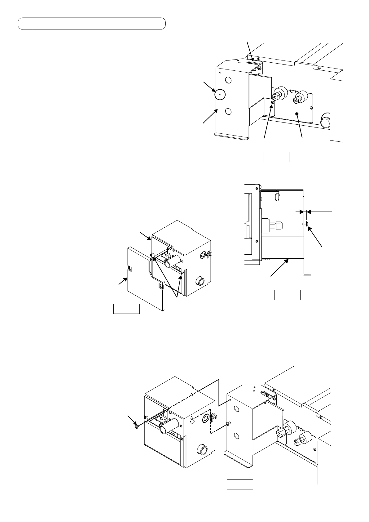
This installation manual contains only the description of how to install the Drain pump PAC-KE07DM-E. For information about how to wire and
how to install air conditioning units, see the installation manual for them.
For your safety, first be sure to read “ 1 Safety Precautions “ described below thoroughly and then install the Drain pump PAC-KE07DM-E
correctly.
This symbol denotes what could lead to serious injury or death if your misuse the PAC-KE07DM-E.
This symbol denotes what could lead to a personal injury or damage to your property if you misuse the PAC-KE07DM-E.
●The following two symbols are used to denote dangers that may be caused by incorrect use and their degree:
●After reading this installation manual, keep it in a place where the final user can see it anytime he or she wants to it.
When someone moves, repairs or uses the PAC-KE07DM-E, make sure that this manual is forwarded to the final user.
.WARNING
.CAUTION
Never use for special applications such as storing food, plants,
precision equipment or art.
The quality of these items may deteriorate.
Always provide adequate signal noise protection when
installing in facilities such as hospitals and communication sta-
tions.
Equipment at these facilities, such as inverters, in-house generators,
high-frequency medical equipment, two-way communication equip-
ment, may cause the air conditioner to operate improperly.
Conversely, the signal noise from the air conditioner may affect the
operation of medical equipment and two-way communication equip-
ment and this could interfere with the medical treatment being given
a patient or cause disturbances or interference in video broadcasting
equipment.
Never operate the air conditioner with the air filter removed.
Particles will enter into the air conditioner and cause damage.
Route wiring so that there is no tension.
Tension could cause the wire to break and this could result in exces-
sive heat or fire.
Dispose of packing materials properly.
Never use the unit in special environments.
Special environments with high concentrations of oil, steam or sulfu-
ric gases will reduce the performance of the air condition and cause
its parts to deteriorate.
Never turn off the power supply immediately after stopping the
unit.
Wait five minutes or more before turning off the power supply.
Turning off the power supply before that time could result in water
leakage or damage.
Never install the unit where run-off could result in damage.
If the humidity in the room exceeds 80% or if the drain becomes
clogged, water may drain off of the indoor unit. When the unit is used
for heating, there may be drainage from the outdoor unit. If required,
provide collector drain for the outdoor unit.
Use care when transporting the unit.
•Always use two or more people for lifting a product weight 20 kg. or
more.
•Some products are packaged with plastic wrapping bands. Never
use these for lifting or transporting the product.
•Never touch the fins on the heat exchanger. They are sharp and
could cause cuts.
•Never allow children to play with the plastic bags used for packag-
ing. Always tear them up when disposing. A child could suffocate
in these bags.
Never touch the switch with wet hands.
Electric shock could occur.
Never operate the air conditioner with the panel or guard
removed.
The hand could come in contact with rotating, hot or high-pressure
components. They could cause electrical shock or entanglement.
MITSUBISHI ELECTRIC
Air Conditioning For Building Application
Drain pump PAC-KE07DM-E
Installation Manual
WT05243X01
1 Safety Precautions
CAUTION
PRECAUTIONS BEFORE INSTALLATION

2
2 Confirming the Supplied Parts
1. Model names and applicable models
Applicable typesModel name
PAC-KE07DM-E
SEZ-M25DA(L), SEZ-M35DA(L), SEZ-M50DA(L)
SEZ-M60DA(L), SEZ-M71DA(L)
PEFY-P15VMS1L-E, PEFY-P20VMS1L-E
PEFY-P25VMS1L-E, PEFY-P32VMS1L-E
PEFY-P40VMS1L-E, PEFY-P50VMS1L-E
PEFY-P63VMS1L-E
Item 12 3 4 5
Quantity 1 1 1
(385mm) (255mm) (200mm)
(100mm)
(380mm)(175mm)
11
Shape
Item 6789 0
Quantity 1 3 3 1 2
Shape
Item
Quantity 1 1 6
Shape
131211
DRAIN PUMP ATTACHMENT DRAIN HOSE 1 PIPE COVER 1 PIPE COVER 2
HOSE BAND SCREW CLAMP FERRITE CLAMP BAND 1
PIPE COVER 3DRAIN HOSE 2 BAND 2
2. Provided parts
Check that the packet includes the following parts in addition to this installation manual.

3
3 Installing the Drain Pump
Hook the 2ATTCHMENT over the mounting bracket on the unit.
(b)
(a)
2ATTACHMENT
Cover
7SCREW
2ATTACHMENT
7SCREW
4~7mm
Cover
1DRAIN PUMP
Cover fixing screws
3-1 Installing the Drain Pump
(1) Unscrew the (a)screw on the unit cover, hook the
2ATTACHMENT over the mounting bracket on the unit,
and screw it on to the unit with the (a)screw. (Fig. 1)
(2) Temporarily screw in the 7SCREW in the hole (b) on
the 2ATTACHMENT. (Fig. 1 and 2)
(3) Loosen the drain-pump-cover fixing screws, and remove
the cover. (Fig. 3)
(4) Hang the 1DRAIN PUMP on the 2ATTACHMENT by
placing the 7SCREW (the one screwed in during Step
(2) above) through the Figure-8 hole on back of the
1DRAIN PUMP, and then tighten the 7SCREW from
inside the 1DRAIN PUMP. (Fig. 4)
Fig. 1
Fig. 2
Fig. 4
Fig. 3

4
3-2 Installing DRAIN HOSE 1
(1) Connect each end of 3DRAIN HOSE 1 to the drain port
on the unit and on the drain pump. (Fig. 5)
✻ Insert the hose all the way to the end of the ports.
✻ Do not use any adhesive.
(2) Secure the hose with 6HOSE BANDs at both ends of
the hose. (Fig. 5)
(3) Attach 4PIPE COVER 1 and 5PIPE COVER 2 to
3DRAIN HOSE 1 flush against each other and against
the unit and the drain pump, and then secure them in
place with CBANDs.
Wrap the pipe cover connection with vinyl tape to close
the gap. (Fig. 6)
3-3 Wiring connections
(1) Remove the CONTROL BOX COVER from the unit by
unscrewing the two screws on the cover. (Fig. 7)
(2) Unscrew the (c)CONTROL BOX fixing screw. (Fig. 7)
3DRAIN HOSE
6HOSE BAND
Fig. 5
4PIPE COVER 1
5PIPE COVER 2
Vinyl tape (locally procured)
To be gap-free
To be gap-free
CBAND 2
CBAND 2
Fig. 6
CONTROL BOX
COVER
(c)
Fig. 7

5
(3) Remove the short-circuit connector from CN4F
on the control board (white, 4P). (Fig. 8)
(4) Route the two drain pump wires behind the CON-
TROL BOX and into the CONTROL BOX.
Lift the CONTROL BOX in the direction of the
arrow (d) to allow the wires through. (Fig. 8)
✻ Do not pinch the wires.
(5) Wind the drain pump wire (connector: blue, 3P)
around 9FERRITE CLAMP once, and fix it in
place with 0BAND. (Fig. 9)
(6) Connect the drain pump wire (connector: blue,
3P) to CNP on the control board, and connect the
float switch wire (white: 4P) to CN4F on the con-
trol board respectively. (Fig. 8)
(7) Place the screw(c) that was removed in Step 3-
3.(2) above back on. (Fig. 7)
(8) Fix the two drain pump wires with 8CLAMPs to
the unit. (Fig. 10)
CN4F CNP
Short-circuit connector
Drain pump wires (2 wires)
(d)
Drain pump wire(2 wires)
8CLAMP
Fig. 8
Blue:3P
20
9FERRITE CLAMP @BAND
Fig. 9
Fig. 10

6
4-1. Insert the ADRAIN HOSE 2 into the drain port (insertion margin: 25mm).
(The drain hose must not be bent more than 45˚to prevent the hose from breaking or clogging.)
(Attach the hose with glue for the hard vinyl chloride pipe, and fix it with the CBAND 2.)
4-2. Attach the drain pipe (O.D. ø32 PVC TUBE, field supply).
(Attach the pipe with glue for the hard vinyl chloride pipe, and fix it with the CBAND 2.)
4-3. Perform insulation work on the drain pipe (O.D. ø32 PVC TUBE) and on the socket (including elbow).
4-4. Check the drainage.
4-5. Attach the BPIPE COVER 3 and, fix it with the CBAND 2 to insulate the drain port.
BPIPE COVER 3
CBAND 2
Visible part Insertion margin
Insertion margin Insulating material (field supply)
Drain pipe
(O.D. ø32 PVC TUBE, field supply)
Max.180 ±5 mm
ADRAIN HOSE 2
CBAND 2
DRAIN PUMP
2535 25
To be gap free. The joint section of the
insulation material meet must be at the top.
•Ensure that the drain piping is downward (pitch of more than 1/100) to the outdoor (discharge) side. Do not provide any trap
or irregularity on the way.
•Ensure that any cross-wise drain piping is less than 20 m (excluding the difference of elevation). If the drain piping is long,
provide metal braces to prevent it from waving. Never provide any air vent pipe. Otherwise drain may be ejected.
•Use a hard vinyl chloride pipe O.D. ø32 for drain piping.
•Ensure that collected pipes are 10 cm lower than the unit body's drain port.
•Do not provide any odor trap at the drain discharge port.
•Put the end of the drain piping in a position where no odor is generated.
•Do not put the end of the drain piping in any drain where ionic gases are generated.
4 Drain piping work
Correct piping
Wrong piping
AInsulation (9 mm or more)
BDownward slope (1/100 or more)
CSupport metal
KAir bleeder
LRaised
MOdor trap
DO. D. ø32 PVC TUBE
EMake it as large as possible.About 10 cm.
FIndoor unit (Drain pump)
GMake the piping size large for grouped piping.
HDownward slope (1/100 or more)
IO. D. ø38 PVC TUBE for grouped piping.
(9 mm or more insulation)
JUp to 580 mm
NDrain hose (accessory)
OHorizontal or slightly upgradient
Grouped piping
C
B
A
L
D
DD
E
K
M
B
HI
Max. 20m
1.5-2m
G
B
J
O
N
F
Max. 300mm
FFF

7
A
A
B
C
D
Insert pump's end 2 to 4 cm.
About 2000 cc
Water
Do not splash water on the drain pump coil or the
float switch wire through hole when pouring water.
D
B
C
SWE
<Indoor board>
Make sure that the drain-up mechanism operates normally
for discharge and that there is no water leakage from the
connections.
•Be sure to confirm the above in a period of heating operation.
•Be sure to confirm the above before ceiling work is done in the
case of a new construction.
•Make sure that water is not leaking from the connection (e) on
the drain pump shown in the right figure.
5 Confirming drain discharge
5-1. Fill water into the feed water pump using a feed water tank. In filling, be sure to put the end of the pump or
tank in a drain pan. (If the insertion is incomplete, water may flow over the machine.)
✻ Do not splash water on the drain pump coil or the float switch wire through hole when pouring water.
5-2. Perform the test run in cooling mode, or turn on the switch SWE on the controller circuit board. (The drain
pump and the fan are forced to operate without any remote controller operation.) Make sure using a transpar-
ent hose that drain is discharged.
5-3. After confirmation, cancel the test run mode, and turn off the main power. When the switch SWE has been
turned on, turn it off, and attach the CONTROL BOX COVER and the DRAIN PUMP COVER in the original
positions.
SWE SWE
ON OFF ON OFF
SEZ model
SWE SWE
OFF ON OFF ON
PEFY model
SWE SWE
ON OFF ON OFF
SEZ model
SWE SWE
OFF ON OFF ON
PEFY model
(e)

Table of contents
Other Mitsubishi Water Pump manuals
Popular Water Pump manuals by other brands

Wilo
Wilo Padus PRO Series Installation and operating instructions

Grundfos
Grundfos EZ Boost 15 BMQE Series Product Guide & Instructions

KNF
KNF N286.15 SP Original Operating and Installation Instructions

Bestway
Bestway Built-in Sidewinder P3150 owner's manual

Graco
Graco Series A repair parts

Linde
Linde HPR-2 manual

QED
QED AutoPump Ultra 4.0 Operation manual

Westward
Westward 29FX04 Operating instructions and parts manual

Grundfos
Grundfos Magna Installation and operating instruction

GORMAN-RUPP
GORMAN-RUPP U3A60S-B Installation, operation and maintenance manual

Wilo
Wilo Sinum quick start guide

Pontec
Pontec PondoVario 1000 operating instructions