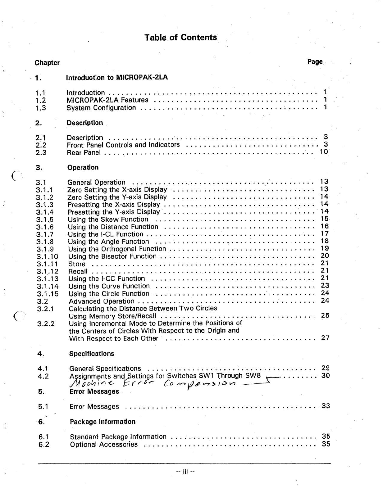
Mitutoyo MICROPAK-2LA User manual

Manual
No.
50AAA945
User's
Manual

Table
of
Contents
Chapter
1
.
Introduction to
MICROPAK-2LA
Page
...............................................
1.1
Introduction
1
.....................................
1.2 MICROPAK-2LA Features
1
........................................
1.3 System Configuration 1
2
.
Description
2.1 Description
..............:................................
3
..............................
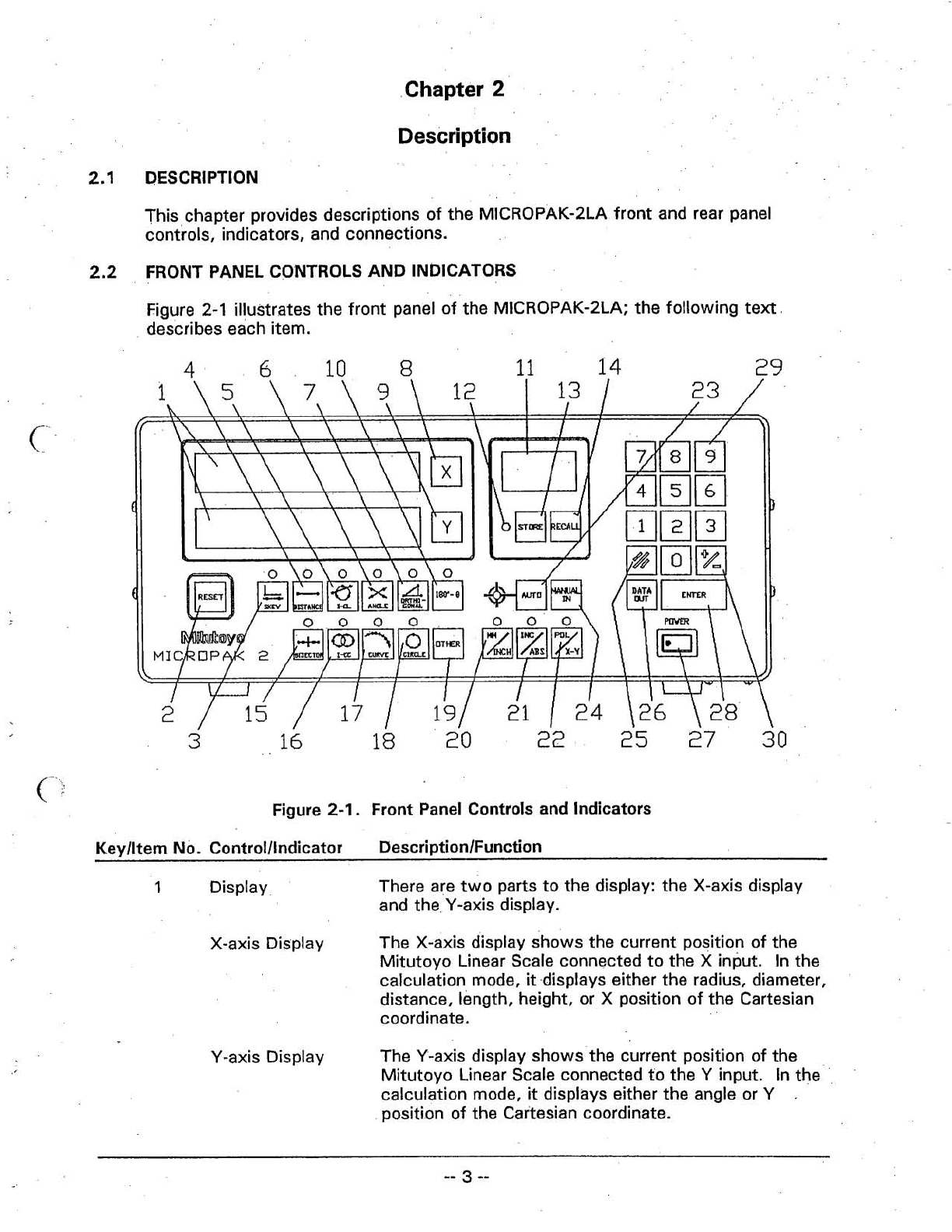
2.2 Front Panel Controls and Indicators
3
2.3
Rear Panel
.............................................:..
10
,-
..
3
.
Operation
............................................
General Operation 13
................................
Zero Setting the X-axis Display 13
................................
Zero Setting the Y-axis Display 14
..................................
Presetting the X-axis Display 14
....................................
Presetting the Y-axis Display 14
....................................
Using the Skew Function 15
..................................
Using the Distance Function 16
......................................
Using the I-CL Function 17
....................................
Using.theAngle Function 18
.................................
Using the Orthogonal Function 19
...................................
Using the Bisector Function 20
Store
..................................................
21
Recall
..................................................
21
.....................................
Using the I-CC Function 21
....................................
Using the Curve Function
23
.....................................
Using the Circle Function
24
........................................
Advanced Operation 24
Calculating the Distance BetweenTwo Circles
...................................
Using Memory StoreIRecall 25
Using Incremental Mode to Determine the Positions of
the Centers of Circles With Respect to the Origin
and
..................................
With Respect to Each Other 27
4
.
Specifications
......................................
4.1 General Specifications
29
.........
4.2 A signments and ettings for Switches SW1 Through
SW8
30
J4eckinc
ErlDC
[0-~,~.,3~
5
.
Error Messages
.
...........................................
5.1 Error Messages 33
6
.
Package Information
6.1 Standard Package Information
.................................
35
.......................................
6.2 Optional
.
Accessories 35

Figure
Tabk
of
Contents
Page
Table
.......................................
System Configuration
1
.............................
Front Panel-Controls and Indicators 3
.............................
Rear Panel Controls and Indicators
10
........................................
Example Template
13
...........................................
Skew Function 15
........................................
Distance Function 16
.............................................
I-CL Function
17
..........................................
Angle Function
18
.......................................
Orthogonal Function 19
.........................................
Bisector Function
20
...........................................
I-CC Function 22
...........................................
Curve Function 23
...........................................
Circle Function 24
Calculating the Distance BetweenTwo Circles Using Memory Store/Recall
.
26
Using INCREMENTAL Mode to Determine the Positions of the Centers of
..............
Circles With Respect to Both the Origiwand Each Other
28
Page
......................................
General Specifications 29
...........................................
SW1 Settings 30
.........................................
SW2 Settings
.
30
...................................
Resolution (SW1 Settings) 31
.......................................
SW3-SW8 Settings 31
..........................................
.Error Messages 33
................................
Standard Package Information 35
...............................
Optional Accessories
..
.....
35

Chapter
1
Introduction to MICROPAK-2LA
1
.I
INTRODUCTION
The MITUTOYO MICROPAK-2LA is designed for the geometric analysis of data
generated bytwo-dimensional measuring instruments such as profile projectors or
tool-maker's microscopes. The MICROPAK-2LA supports linear scales.
1.2
MICROPAK-2LA FEATURES
Features of the MICROPAK-2LA include:
PolarICartesian function
INCIABS function
Skew function
Distance function
Bisector function
Circle function
Orthogonal function
lntersection of Circle and Line function
lntersection of Circle and Circle function
Multi-point
(1
0
points) Curve function
Fast and easy storing with the capability of recalling upto
50
sets
of
XI
Y
coordinate data
High reliability and durability of membrane keys
Capable of interfacing with Edge Sensor System
1.3 SYSTEM CONFIGURATION
The following figure illustrates how the MICROPAK-2LA interconnects with other
equipment.
LINEAR
SCALE
TO
HOST
EIA-232-D
COMPUTER
OR
SERIAL
MITUTOYO
OUTPUT UNIT
SYSTEMS
M
ICROPAK-2LA
OPTIONAL
ACCESSORIES
Figure
1-1.
System Configuration

This Page is Intentionally Left Blank.

Chapter
2
Description
2.1
DESCRIPTION
This chapter provides descriptions of the MICROPAK-2LA front and rear panel
controls, indicators, and connections.
FRONT PANEL CONTROLS AND INDICATORS
Figure
2-1
illustrates the front panel of the MICROPAK-2LA; the following text
describes each item.
Figure
2-1.
Front Panel Controls and Indicators
Kevlltem
No.
Controlllndicator DescriptionlFunctian
1
Display There are two parts tothe display: the X-axis display
and the.Y-axis display.
X-axis Display The X-axis display shows the current position of the
Mitutoyo Linear Scale connected to the X input.
In
the
calculation mode,
it
displays either the radius, diameter,
distance, length, height, or X position of the Cartesian
coordinate.
Y-axis Display The Y-axis display shows the current position of the
Mitutoyo Linear Scale connected to the Y input.
In
the
calculation mode,
it
displays either the angle or Y
,
position of the Cartesian coordinate.

Keylltem No. Controlllndicator Description/Function
3
Skew
Pressing the [RESET] key restores the MICROPAK-2LA
to its initial'condition without clearing previously stored
sets of coordinate data.
The Skew function allows the MICROPAK-2LA to
electronically align the desired part coordinate tothe
machine
X,
Y
coordinates.
Pressing the [SKEW] key initiates the Skew function.
Pressing the [SKEW] key again aborts the Skew
function. After measurement points have been taken,
each depression of the [SKEW] key clears one
measurement point until all measurement points are
cleared. Once all measurement points are cleared,
pressing the [SKEW] key again aborts the Skew
I
function.
,
Skew indicator This LED indicates the status of the Skew function.
<
When illuminated, the Skew function is activated.
4
Distance The Distance function enables the user to measure the
distance between any two points.
Pressing the [DISTANCE] key initiates the Distance
function.
.
Pressing the [CLEAR] key aborts this
function. After measurement points have been taken,
each depression of the [DISTANCE] key clears one
measurement point until ail measurement points are
cleared. After all measurement points are cleared,
further depressions of the [DISTANCE] key have no
effect.
Distance lndicator This LED indicates the status of the Distance function.
When illuminated, the Distance function isactivated.
5
I-Ci(Intersection The I-CL function enables the user tolocate the
of Circle and Line) intersecting point(s) betweena circle and a line.
Pressing the [I-CLI key initiates the lntersection of
Circle and Line function. Pressing the [CLEAR] key
aborts this function. After measurement points have
been taken, each depression of the [I-CLI key clears one
measurement point until all measurement points are
cleared. After
all
measurement points are cleared,
further depressions of the [I-CLI key have no effect.
I-CL Indicator This LED indicates the status of the Intersection of
Circle and Line function. When illuminated, the
lntersection of Circle and Line function is activated.

Keylltem No. Controlllndicator
.
DescriptionlFunction
6
Angle The Angle function enables the user to locate the point
of intersection and measure the angle formed by two
straight lines.
Pressing the [ANGLE] key initiates the Angle function.
Pressing the [CLEAR] key aborts this function. After
measurement points have been taken, each depression
of the [ANGLEI key clears one measurement point until
all measurement points are cleared. After all
measurement points are cleared, further depressions of
the [ANGLE] key have no effect.
Angle Indicator This LED indicates the status of the Angle function.
When illuminated, the Angle function is activated.
7
Orthogonal The Orthogonal function enables the user to: measure
an angle; determine the distance perpendicularly from
one line of the angle to a specified point on the
opposite line; and locate the point of intersection with
the first line.
Pressing the [ORTHOGONAL] key initiates the
Orthogonal function. Pressing the [CLEAR] key aborts
this function. After measurement points have been
taken, each depression of the [ORTHOGONAL] key
clears one measurement point until all measurement
points are cleared. After all measurement points are
cleared, further depressions of the [ORTHOGONAL] key
have no effect.
Orthogonal lndicator This LED indicates the status of the Orthogonal
function. When illuminated, the Orthogonal function is
activated.
The
[XI
key is used toeither Zero Set or Preset the
X-axis display.
The [Yl key is used to either Zero Set or Preset the
Y-axis'display.
10 180"-0 The 180°
-
O
function displays the angle equal to
1
80°
-
0.
The 180°
-
O
function niay only be used in
conjunction with the Angle or Orthogonal functions.
Pressing the
[I
80°
-
01
key generates theangle that is
180 minus the currently displayed calculated angle.
1
80°
-
O
lndicator This LED indicatesthe status
of
the 180°
-
O
function.
When illuminated, the 1
80°
-
O
function is activated.

KeylltemNo. Controlllndicator
12
Store or Recall
lndicator
15
Bisector
BISECTOR
El
Bisector lndicator
16
I-CC (Intersection
of Circle and
Circle)
I-CC lndicator
The Sub-Display is used to display either the memory
location
(0
to 50) or the remaining number of points to
be measured (PO0 toP10, depending on the geometric
function selected). The Sub-Display will return to
00
after storing or recalling measurement data and clearing
the function after all points
in
a geometric function are
measured.
This LED is illuminated whenever the Store or Recall
functions are activated;
The Store function isused to store a set of coordinate
data at any memory location from
0
to 50. Under
normal operation, the displayed coordinate data is
stored.
In
the calculation mode, the calculated point is
stored. Data stored
in
memory is not affected bythe
Reset function. However, all data stored
in
memory is
lost when the power isturned OFF.
The Recall function isusedto recall the set of
coordinate data or the point data from a previously
stored memory location.
The Bisector function enables the user to calculate half
the distance of a specified line and determine the
location of the bisecting point.
Pressing the [BISECTOR] key initiates the Bisector
function. Pressing the [CLEAR] key aborts this
function. After measurement points have been taken,
each depression of the [BISECTOR] key clears one
measurement point until all measurement points are
cleared. After all measurement points are cleared,
further depressions ofthe IBISECTORI key have no
effect.
This LED indicates the status of the Bisector function.
When illuminated, the Bisector function is activated.
The I-CC function enabies the user to determine the
location of the intersecting point(s1 between two
circles.
Pressing the [I-CCI key initiates the I-CC function.
Pressing the [CLEAR] key aborts this function. After
measurement points have been taken, each depression
of the [I-CCI key clears one measurement point until all
measurement points are cleared. After all measurement
points are cleared, further depressions of the [I-CCI
key have no effect.
This LED indicatesthe status of the I-CC function.
When illuminated, the I-CC function is activated.

Keylltem
No.
Control/lndicator DescriptionlFunction
17
Curve (Multi-Point The Curve function enables the user to measure the
Circle) radius and loc;ate the center position of a curve.
Pressing the [CURVE] key initiates the Curve function.
Pressing the [CLEAR] key aborts this function. After
measurement points have been taken, each depression
of the [CURVE] keyclears one measurement point until
all measurement points are cleared. After all
measurement points are cleared, further depressions of
the [CURVE] key have no effect.
Curve Indicator This LED indicatesthe status of the Curve function.
When illuminated, the Curve function is activated.
18
Circle The Circle function enables the user to measure the
diameter and !ocate the center position of a circle.
Pressing the [CIRCLE] key initiates the Circle function.
Pressing the [CLEAR] key aborts this function. After
measurement points have been taken, each depression
of the [CIRCLE] key clears one measurement point until
all measurement points are cleared. After all
measurement points are cleared, further depressions of
the [CIRCLE] key have no effect.
Circle Indicator This LED indicates the status of the Circle function.
When illuminated, the Circle function is activated.
OTHER
19'
Pressing the [OTHER] key enables the user to observe
the calculated point
in
the following geometric
functions: I-CL, Angle, Curve, Orthogonal, Bisector,
and circle.
20
MMIINCH The MMIINCH function enables the user toselect either
the INCH or
MM
(millimeters)'mode of operation.
Pressing the MMllNCH key alternates the measuring
unit between the.INCH and MMmodes.
MMIINCH lndicator This LED indicates the status of the MMIINCH function.
When the indicator
is
illuminated, the measurement is in
the MMmode; otherwise,
it
is inthe INCH mode.
21
INCIABS The INCIABS function enables the user toselect either
the ABSOLUTE or INCREMENTALmode of operation.
Inthe ABSOLUTE mocie, location data is calculated
with respect tothe origin of the current coordinate
system. Inthe INCREMENTALmode, location data is
calculated with respect tothe last measurement
location. While inthe INCREMENTALmode, pressing
the [OTHER] key, switches the displayed data between
ABSOLUTE and INCREMENTAL.

Keylltem No. Control/lndicator
INCIABS lndicator
22
POLIX-Y
POLIX-Y lndicator
.23 AUTO
AUTO lndicator
24
Pressing the [INCIABSI key alternates betweenthe
ABSOLUTE and INCREMENTALmodes. Note that the
INCREMENTAL mode is only operable when performing
geometric analysis.
This LED indicates the status.of the INCIABSfunction.
When the indicator isilluminated, the measurement is
in
the INCREMENTALmode; otherwise,
it
is
in
the
ABSOLUTE mode.
(
The POLIX-Y function enables the user tochange the
display betweeneither POLAR or X-Y (Cartesian)
coordinate systems. The POLAR mode must be
inactive inorder toperform measurements;
it
is for
viewing previously measured data only.
Pressing the [POLIX-YI key alternates betweenthe
POLAR and X-Y modes.
'-
This LED indicates the status of the POLIX-Y function.
When the indicator isilluminated, the system is inthe
POLAR mode; otherwise,
it
is
in
the X-Y mode.
The AUTO function enables the user.tointerfa'ce the
MICROPAK-2LA with the.
MITUTOYO Optoeye El (Edge
Sensor) for automatically detecting the edge between
dark and light areas of a part.
Pressing the [AUTO] key alternates betweenenabling
and disabling the connected edge sensor. While in
Auto mode, pressing the [MANUAL IN1key measures
the current point. Note that for [MANUAL IN] keyto
work while auto light is
lit,
the optical sensor must
reside on the non-triggering region or the [AUTO]
function must be disabled.
This LED indicates the status of the AUTO function.
When the indicator is illuminated, the connected edge
sensor is enabled; otherwise,
it
is disabled.
The [MANUAL IN] key enables the user to input the
desired point of coordinate data to be used inthe
geometric calculation.
The [CLEAR] key enables the user toclear the Preset
function and the error messages El and E2 caused by
the EIA-232D output module and geometric calculation,
respectively.
It
isalso used to abort the Store, Recall,
and geometric functions.

KeylltemNo. Controlllndicator DescriptionIFunction
The [DATA
OUT]
key is used to output the data
through either the Digimatic Code-Out unit or EIA-232D
output unit. Referto the Digimatic Code Output Unit
0peration.Manual (No. 029615) and the EIA-232D
Output Unit Operation Manual (No. 02961
6) for further
information.
/
This switch turns the ~bwertothe MICROPAK-2LA ON
or -OFF.
The [ENTER]key is used to enter preset data and
memory locations for storing or recalling data.
(.
.
-:
29
NUMERIC
KEYPAD
The numeric keypad is used to select preset or memory
location data usingthe number keys
[Ol
through
t91.
Pressing this key alternates the polarity of the selected
data between positive and negative. This key may be
used at any time during the data selection.until the data
is entered.

2.3
REAR
PANEL
Figure 2-2 illustrates the rear panel of the MICROPAK-2LA; the following text
describes each item.
CAUTIONFIR
cmnwn
rnC'TIPI
FIRE,
-AQ
1
mm
MrnWWI
LILY
WTH
ME
OF
SECUIEI)
TYPE
AW
Rhnw
L
1)
W
\
1
I
-
7
8
Figure
2-2.
Rear Panel Controls and Indicators
Keylltem
No.
Controlllndicator DescriptionlFunction
c
1
DC-OUT The DC-OUT port supplies the required power to the
optional Optoeye El Edge Sensor.
3
EDGE IN
The AC IN receptacle connects toan AC power outlet.
Itaccepts voltages between
90
and 264VAC at
50
or
60
Hz.
The EDGE IN port connects to the output of the
optional Optoeye El or E2.
4
EXT. MANUAL IN The EXT. MANUAL INjack connects tothe optional
Footswitch which is used toinput the desired point of
coordinate data for geometric calculations.
A footswitch, when connected, performsthe same
function as the [MANUAL IN] key.

Kevlltem
No.
Controlllndicator Descri~tionlFunction
5
Input Module The input module connects the MICROPAK-2LA to a
(Linear Scale) Linear Scale. lnput module is pre-installed inthe
MICROPAK-2LA.
Linear Scale This input init-isinstalled at the factory before
Input Unit shipment. The resolution of the MICROPAK-2LA is
dependent on whether J1 and J2 are installed on this
board. To select a resolution of 0.001 mm on the
MICROPAK-2LA (seeTable
4-41,
J1 and J2 must be
open.
To
select a resolution of 0.0005 mm, Jland J2
must be shorted with the supplied headers.
6
.
Output Module The optional Mitutoyo output modules, the EIA-232D
Slot (RS-232C) or the Digimatic Code-Out, may be installed
for output capability.
7
Fuse Holder The fuse holder holds the current workjng fuse and one
spare fuse.
8
GND (Frame- The Frame-Ground Terminal connects the MICROPAK-
Ground Terminal) 2LA tothe earth ground.

This
Page
is
Intentionally Left Blank.

Chapter
3
Operation
GENERAL OPERATION
This chapter provides operating instructions for the MICROPAK-2LA. Figure
3-1
illustrates the template that will be used inthe examples throughout this chapter.
MICROPAK-2LA supports twodifferent coordinate systems. One isthe machine
X-
Y
coordinate system and the other is the skewed coordinate system, which is
created by skewing the original X-Y machine coordinate system.
NOT
TO
SCALE
DlMENSlMJS
ON
PART
ARE
FOR
REFERENCE
ONLY
Figure 3-1. ExampleTemplate
. .
3.1
.I
ZERO
SETTING THE
X-AXIS
DISPLAY
To zero set the X-axis display, perform the following steps:
1.
Pressthe [XI key.
2.
Pressthe [ENTER] key.
i
NOTE: Pressingthe [XI key again before pressing the [ENTER] key
aborts the Zero Set function.

i
. .
3.1.2
ZERO SETTING THE Y-AXIS DISPLAY
Tozero set'theY-axis display, perform the following steps:
1
.
Press the [Yl key.
2.
Press the [ENTER] key.
NOTE: Pressing the [Yl key again before pressing the [ENTER] key
aborts the Zero Set function.
f
3.1.3
PRESETTING THE X-AXIS DISPLAY
Topreset the X-axis display toa predetermined value, press the following keys.
In
this example, the]X-axis will-be preset to
12345.678.
In
normal mode, the X-axis Display is incremented from the preset value.
In
Auto
mode, the X-axis Display will not increment until the edge sensor istriggered. Then
the display is continually updated as measurements are made.
NOTE: If the wrong number isentered, pressing the [CLEAR] key enables the
user tore-enter the correct numbers. Pressing the
[XI
key again before
pressing the [ENTER] key aborts the.Preset function.
NOTE: The number of decimal places is dependent upon the resolution of the
MICROPAK-2LA.
3.1.4
PRESETTING
THE
Y-AXIS
DISPLAY
To preset the Y-axis display to a predetermined value, press the following keys.
Inthis example, the Y-axis will be preset to
-1
234.567.
c,
Innormal mode, the Y-axis Display is incremented from the preset value.
In
Auto
mode, the Y-axis Display will not increment until the edge sensor istriggered. Then
the display is continually updated as measurements are made.
NOTE: If the wrong number is entered, pressing the [CLEAR] key enables the
user to re-enter the correct numbers. Pressing the [Yl keyagain before
pressing the [ENTER] key, aborts the Preset function.
NOTE: The number of decimal places is dependent upon the resolution of the
MICROPAK-2LA.

3.1.5
USINGTHE SKEW FUNCTION
,
.
To skew the current coordinate system, refer to Figure
3-2
and perform the
following steps:
1.
Press the [SKEW] key. The Skew Indicator will illuminate and
P03
will
appear on the Sub-Display, indicatingthat three points need to,be measured.
2.
Move the crosshairs totarget on P,,, then press either the [MANUAL IN] key
or the footswitch.
P02
will appear on the Sub-Display, indicating that there
are two points remaining to be measured.
3.
Move the crosshairs totarget on P,,, then press either the [MANUAL IN] key
or the footswitch. The new direction of the X-axis isnow set. will
appear on the Sub-Display, indicating that there isone point remaining to be
measured.
4.
Move the crosshairs to target on
P,,,
then press either the [MANUAL IN] key
or the footswitch. This sets the new origin.
POO
will appear on the Sub-
Display, indicating that there are no points remaining to be measured.
5.
The machine coordinates are now skewed to align with the part coordinates
as indicated by
X'
and
Y'
in
Figure
3-2.
Press the
[SKEW]
key again to
deactivate the Skew function. The Skew Indicator will extinguish.,
NOTE:
Selecting P,, and P, as far apart as possible' increases measuring
accuracy.
Figure
3-2.
Skew Function

3.1.6
USING THE DISTANCE FUNCTION
To calculate the distance between two points, refer to Figure
3-3
and perform the
following steps:
1.
Press the [DISTANCE] key. The Distance Indicator will illuminate and
will appear on the Sub-Display, indicating that twopoints needto be
measured.
2.
Move the crosshairs totarget on P,,, then press either the [MANUAL IN] key
or the footswitch. will appear on the Sub-Display, indicating that there
is one point remaining to be measured.
3.
Move the crosshairs to target on P,,, then press either the [MANUAL IN] key
or the footswitch. will appear on the Sub-Display, indicating that there
are no points remaining to be measured.
The distance L is then calculated and displayed on the X-axis display.
4.
Press the [CLEAR] key todeactivate the Distance function. The Distance
Indicator will extinguish. Pressing another function key will initiate that
function.
Figure
3-3.
Distance Function

3.1.7
USING THE I-CL FUNCTION
To calculate the'points of intersection between a circle and a line, refer to
Figure
3-4
and perform the following steps:
1.
Press the [I-CL] key. The I-CL I.ndicatorwill illuminate and
P05
will appear
on the Sub-Display, indicating that five points need to be measured.
2.
Move the crosshairs to target on P,,, then press either the [MANUAL IN] key
or the footswitch.
P04
will appear on the Sub-Display, indicatingthatthere
are four points remaining tobe measured.
3.
Move the crosshairs to target on P,,, then press either the [MANUAL IN] key
or the footswitch. This defines the line. will appear on the
Sub-Display, indicating that there are three points remaining to be measured.
4.
Move the crosshairs to target on P,,, then press either the [MANUAL IN] key
or the footswitch.
P02
will appear on the Sub-Display, indicating that there
are two points remaining tobe measured.
5.
Move the crosshairs totarget on P,,, then press either the [MANUAL IN] key
or the footswitch. will appear on the Sub-Display, indicating that there
is one point remaining to be measured.
6.
Move the crosshairs to target on P,,, then press either the [MANUAL IN] key
or the footswitch. This defines the circle. will appear on the
Sub-Display, indicating that there are no p.ointsremaining to be measured.
The point Poisthen calculated and displayed on the X-axis and Y-axis
displays.
7.
If the measuring order is switched to P,,, P,,, P,,,
P,,
and P,,, the calculated
point Pis displayed instead.
8.
Press the [CLEAR] key to deactivate the I-CLfunction. The I-CL Indicator
will extinguish. Pressing another function key wilt initiate that function.
Figure
3-4.
I-CL Function
Table of contents
Other Mitutoyo Laboratory Equipment manuals
Popular Laboratory Equipment manuals by other brands

Thermo Scientific
Thermo Scientific Neslab Merlin M 25 Installation, Operation, Basic Maintenance

Tuttnauer
Tuttnauer 2540 EHS Operation & maintenance manual

Elmi
Elmi DOS-10M user manual

INTEGRA Biosciences
INTEGRA Biosciences PIPETBOY comfort operating instructions

nanoString
nanoString GeoMx DSP user manual

Leica
Leica HI1220 Instructions for use

Tektronix
Tektronix 1741C user manual

CBM
CBM PANACEA ELETTRONICA 2429/V user manual

Malvern Instruments
Malvern Instruments Spraytec user manual

Altronix
Altronix NetWay112 installation guide

Endress+Hauser
Endress+Hauser analytikjena Biometra TAdvanced Short manual

VWR
VWR Gel Documentation Imager2 instruction manual