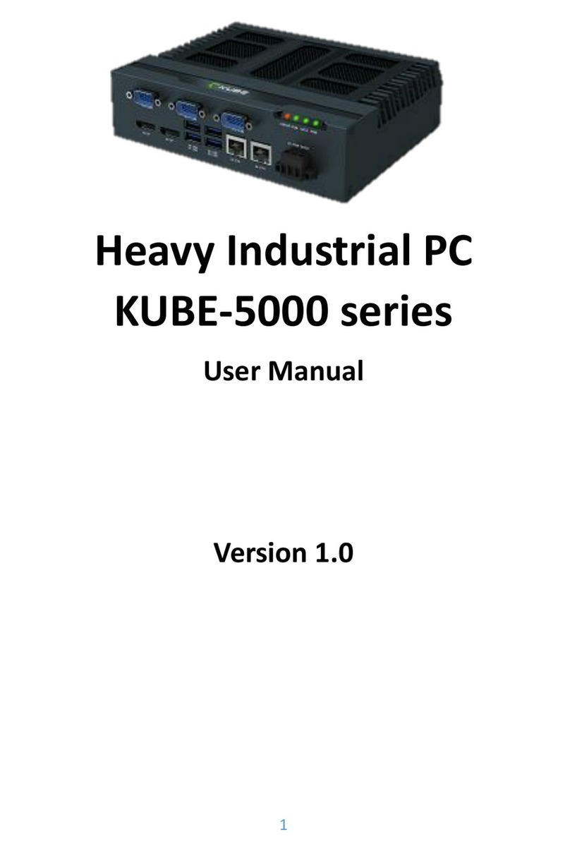
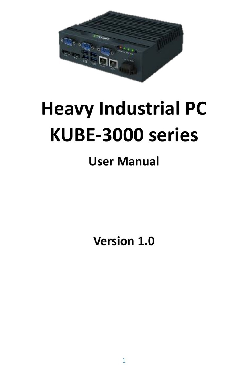
MiTWell KUBER-2000 Series User manual

MITWELL KUBER-2000 Series User Manual - Preliminary
Copyright © MITWELL 2019 KUBER-2000 Series User Manual
1
KUBER-2000 Series
User Manual
Preliminary Version

MITWELL KUBER-2000 Series User Manual - Preliminary
Copyright © MITWELL 2019 KUBER-2000 Series User Manual
2
Table of Contents
1REVISION....................................................................................................... 4
2PREFACE........................................................................................................ 5
2.1 Copyright................................................................................................5
2.2 Acknowledgement .................................................................................5
2.3 Warranty ................................................................................................5
2.4 Declaration of conformity......................................................................6
2.5 Technical support...................................................................................6
3INTRODUCTION............................................................................................. 7
3.1 Product overview...................................................................................7
3.2 Safety Precautions..................................................................................8
3.3 Hardware Specification..........................................................................9
3.4 Appearance..........................................................................................11
3.4.1 KUBER-2110 .................................................................................11
3.4.2 KUBER-212A.................................................................................11
3.4.3 KUBER-212B.................................................................................11
3.4.4 KUBER-212D.................................................................................12
3.4.5 KUBER-212E .................................................................................12
3.5 Interface...............................................................................................13
3.5.1 USB 3.0.........................................................................................13
3.5.2 DP.................................................................................................13
3.5.3 Ethernet .......................................................................................13
3.5.4 LED indicator ................................................................................14
3.5.5 COM .............................................................................................14
3.5.6 Power terminal.............................................................................15
3.5.7 M.2 and mini PCI-e card slot........................................................15
3.5.8 Antenna........................................................................................15
3.6 Dimensions...........................................................................................16
3.6.1 One layer......................................................................................16
3.6.2 Two layer......................................................................................17
4SYSTEM INSTALLATION..................................................................................19
4.1 Wall mount...........................................................................................19
4.2 DIN-Rail mount.....................................................................................21
5INITIAL SETUP...............................................................................................23
5.1 Chassis Grounding................................................................................23

MITWELL KUBER-2000 Series User Manual - Preliminary
Copyright © MITWELL 2019 KUBER-2000 Series User Manual
3
5.2 Connecting Power................................................................................23
5.3 External Antenna installation...............................................................24
6MAINTENANCE.............................................................................................25
6.1 M.2 2230 Wifi Module Installation......................................................25
6.2 M.2 2242 and Mini PCI-e card installation...........................................27
6.3 Battery change .....................................................................................29
AAPPENDIX.....................................................................................................30
A.1 Naming rule..........................................................................................30
A.2 System ordering information ...............................................................31
A.3 Accessory ordering information...........................................................32
A.4 Golden finger pin-out table .................................................................32

MITWELL KUBER-2000 Series User Manual - Preliminary
Copyright © MITWELL 2019 KUBER-2000 Series User Manual
4
1REVISION
Revision
Date
Page
Description
R1.0
20190731
Initial document release (Preliminary)

MITWELL KUBER-2000 Series User Manual - Preliminary
Copyright © MITWELL 2019 KUBER-2000 Series User Manual
5
2PREFACE
2.1 Copyright
This document is released and copyrighted are reserved by MiTwell, Inc. No parts of
this document may be copied, reproduced by mechanical, electronics or other means
in any form, for any purpose, without prior authorization by MiTwell, Inc.
The information contained within this user manual, including but not limited to any
other product specification, MiTwell, Inc reserves its right to modify them at any time
without notice.
2.2 Acknowledgement
Intel®, Core™ and Atom™ are the trademarks of Intel Corporation. Microsoft Windows
and MS-DOS are registered trademarks of Microsoft Corp. All other product names or
trademarks are properties of their respective owners. All product names, logos, brands,
trademarks and registered trademarks in this user’s manual or the MiTwell website
are the property of their respective owners.
2.3 Warranty
MiTwell warrants that each product failing to function properly under normal use for
12 months from the invoice date. Due to an effect in materials, workmanship or due
to nonconformance upon specifications, will be repaired or exchanged at MiTwell’s
option and expense.
For RMA and DOA goods, customers should follow the standard procedure and send
back the goods. For detail please see the warranty policy by below link:
http://rma.portwell.com.tw:10007/mitwellrma/Default.aspx

MITWELL KUBER-2000 Series User Manual - Preliminary
Copyright © MITWELL 2019 KUBER-2000 Series User Manual
6
2.4 Declaration of conformity
CE (European Union)
This equipment is in conformity with the requirement of the following EU legislations
and harmonized standards. Product also complies with the Council directions. (EN
61000-6-4, Class A, EN 61000-6-2)
FCC (Federal Communications Commission Radio Frequency Interface Statement)
This device complies with part 15 FCC rules. This equipment has been tested and found
to comply with the limits for a Class A digital device, pursuant to part 15 of the FCC
Rules. (CFR Title 47 Part15 Subpart B: 2018 Class A)
Operation is subject to the following two conditions: one is the device may not cause
harmful interference, and second is that the device must accept any interference
received including interference that may cause undesired operation.
2.5 Technical support
MiTwell are committed to provide the best support and service for our customers,
which can help customer implement and use MiTwell’s products easily.
We suggest that you download the latest documentation, utilities and drivers which
have been made available to assist you on MiTwell website. If you still require
assistance after visiting our website, you can contact your local sales and technical
support team for further assistance.
For more information on this and other products, please visit our websites at:
http://www.mitwell.com.tw

MITWELL KUBER-2000 Series User Manual - Preliminary
Copyright © MITWELL 2019 KUBER-2000 Series User Manual
7
3INTRODUCTION
3.1 Product overview
KUBER-2000 series is a new generation of palm-sized, flexible and ready-to-use industrial
PC designed for a variety of applications in the industrial 4.0 world. Within 10cm length,
you can expect scalable Apollo Lake processors up to 4 cores, robust aluminum housing
and common industrial features.
The state-of-the-art expansion design ensures various I/O choices for different
applications are fulfilled with minimal investment. Leveraging KUBER-2000’s Eco system,
you can shorten the time to market when building your own solutions.
No matter to perform data collection and transition, edge computing or communication
tasks in applications like industrial automation, intralogistics or smart retailers, KUBER-
2000 series are proved to be your best choice.

MITWELL KUBER-2000 Series User Manual - Preliminary
Copyright © MITWELL 2019 KUBER-2000 Series User Manual
8
3.2 Safety Precautions
Warning note
This symbol indicates hazards that could lead to personal injury. There are three signal
words indicating the severity of a potential injury.
DANGER
Indicates a hazard with a high risk level. If this hazardous
situation is not avoided, it will result in death or serious injury.
WARNING
Indicates a hazard with a medium risk level. If this hazardous
situation is not avoided, it could result in death or serious injury.
CAUTION
Indicates a hazard with a low risk level. If this hazardous situation
is not avoided, it could result in minor or moderate injury.
This symbol together with the NOTE signal word alerts the reader
to a situation which may cause damage or malfunction to the
device, hardware/software, or surrounding property.
Here you will find additional information or detailed sources of
information.

MITWELL KUBER-2000 Series User Manual - Preliminary
Copyright © MITWELL 2019 KUBER-2000 Series User Manual
9
3.3 Hardware Specification
Model Name
KUBER- 2110
KUBER - 212A
KUBER - 212B
KUBER - 212D
KUBER - 212E
KUBER - 212G
CPU
Intel® Celeron N3350, 2 cores, 1.1GHz/2.4 GHz, 6W TDP
Memory
4GB onboard LPDDR4, 2400MT/S memory
Mass Storage
32GB onboard eMMC 5.0 flash; up to 256 GB (optional)
Power Input
12-30VDC (+/- 20%)
Indicator LED
Power (Green), Run (Green)
Operating Systems
Windows® 10 IoT Enterprise LTSB 2016 (64-bit) / Linux Yocto v2.5.1
Expansion
1 x M.2 Key E 2230
Basic I/O Interface
Power Connection
1 x 2-pin screw-type terminal block
Ethernet
2 x 10/100/1000 GbE (Intel® i210)
USB
2 x USB 3.0
Display
1 x DP v1.4 4096 x 2160 @ 60Hz
Environment
Operating Temperature
0 °C ~ 50 °C @ 5~85% RH with no airflow
Storage Temperature
-40 °C ~ 85 °C
Vibration
1g (DIN EN 60068-2-6)
Shock
15g (EN 60068-2-27)
Certification
CE, FCC (EN55022, EN55032)
CE (EN 61000-6-4, Class A, EN 61000-6-2) FCC (CFR Title 47 Part15 Subpart B: 2018
Class A)
Mechanical
Degree of Protection
IP30
Dimension (mm)
99x 46x 92
99 x 63 x 92
Net Weight (Kg)
0.55
0.65
Mounting
DIN rail and wall mounting options
Cooling
Fanless

MITWELL KUBER-2000 Series User Manual - Preliminary
Copyright © MITWELL 2019 KUBER-2000 Series User Manual
10
Extended I/O Interface
Model Name
KUBER - 212A
KUBER - 212B
KUBER - 212D
KUBER - 212E
KUBER - 212G
Power connection
N/A
N/A
1 x 2-pin screw-
type terminal
block (48VDC)
N/A
N/A
Ethernet/ POE
2 x 10/100/1000 GbE
(Intel® i210), with
isolation
2 x
10/100/1000
GbE
(Intel® i210)
2 x 802.3af PoE
GbE (15.4W)
N/A
N/A
COM/Console
1 x RS-232/422/485
(BIOS configurable, 5V
& 12V selectable),
with isolation
1 x CANbus
N/A
1 x RS-232
1 x RS-232/422/485
(BIOS Configurable)
2 x RS-232
By RJ45
USB
N/A
N/A
N/A
N/A
4 x USB 2.0
I/O
N/A
4 x GPIO
N/A
N/A
N/A
Expansion Slot
N/A
1 x Mini-
PCIe/mSATA
1 x M.2 Key E
2230
N/A
1 x M.2 Key B 2242
1 x Mini-PCIe
1 x M.2 Key B
2242
1 x Mini-PCIe

MITWELL KUBER-2000 Series User Manual - Preliminary
Copyright © MITWELL 2019 KUBER-2000 Series User Manual
11
3.4 Appearance
3.4.1 KUBER-2110
Core interface with 2x USB3.0, 1x DisplayPort,
2xGiga LAN, Power connectors
3.4.2 KUBER-212A
Expanded interface with 2x isolated LAN
1 x RS-232/422/485 (BIOS configurable, 5V & 12V selectable)
3.4.3 KUBER-212B
Expanded interface with 4x GPIO, 1x CANBus, 2x Giga LAN

MITWELL KUBER-2000 Series User Manual - Preliminary
Copyright © MITWELL 2019 KUBER-2000 Series User Manual
12
3.4.4 KUBER-212D
Expanded interface with 1 x 2-pin screw Terminal block (48VDC)
3 x 10/100/1000 GbE with PoE (15.4W)
3.4.5 KUBER-212E
Expanded interface with 1 x RS-232
1 x RS-232/422/485 (BIOS Configurable)

MITWELL KUBER-2000 Series User Manual - Preliminary
Copyright © MITWELL 2019 KUBER-2000 Series User Manual
13
3.5 Interface
3.5.1 USB 3.0
USB 3.0 ports utilize a blue connector. USB 2.0 ports are black.
KUBER-2000 core computing part provides two USB Type-A 3.0 to connect
external device such as mouse, keyboard or external storage device. Two ports
are USB 3.0. USB 3.0 ports utilize a blue connector.
3.5.2 DP
DisplayPort (DP): These ports connect KUBER-2000 to external digital displays
with a corresponding DP++ connector.
3.5.3 Ethernet
KUBER-2000 series are equipped with Intel® i210 Gigabit LAN controller, which
fully compliant with 10/100/1000 Base-T Ethernet network. Two RJ45
connectors allow the computer to communicate on a 10/100/1000 Base-T
Gigabit LAN Ethernet network.
Activity Link LED
Speed LED
Status
Description
Status
Description
Off
No link
Off
10 Mbps connection
Orange
Linked
Orange
100Mbps connection
Orange(blink)
Data activity
Green
1 Gbps connection

MITWELL KUBER-2000 Series User Manual - Preliminary
Copyright © MITWELL 2019 KUBER-2000 Series User Manual
14
3.5.4 LED indicator
Two LEDs are provided on the KUBER-2000. These LEDs provide operating
information.
Function*
Status
Description
Power
Power ON
Solid Green
Power Off
Off
Run Status
(GPIO)
Run
Flash Green
off
Off
*: Need to auto detection functionality while power applied
3.5.5 COM
Serial (COM): D-SUB 9 serial ports are available for use, which is configurable
as either RS-232, RS-422, or RS-485 by BIOS setting. The function of the pins
in the D-SUB 9 connector varies with the different configuration settings on
different model, please check it on the datasheet.
D-SUB 9 pin
RS-232
RS-422
RS-485
1
DCD
TXD-
TXD-/RXD-
2
RXD
TXD+
TXD+/RXD+
3
TXD
RXD+
-
4
DTR
RXD-
-
5
GND
GND
GND
6
DSR
-
-
7
TRS
-
-
8
CTS
-
-
9
Ring indicator
-
-

MITWELL KUBER-2000 Series User Manual - Preliminary
Copyright © MITWELL 2019 KUBER-2000 Series User Manual
15
3.5.6 Power terminal
2-pin screw-type terminal block is provided for connecting power to the
KUBER-2000
Pin No.
Description
-
0 V DC
+
12-30VDC (+/- 20%)
3.5.7 M.2 and mini PCI-e card slot
Release the screw and disassemble the chassis of KUBER-2000, you can see
the M.2 and miniPCI-e card slot on the main board/carrier board. The slot
varies with the different models.
3.5.8 Antenna
A mini PCIe card/M.2 2230 card slot is available to allow KUBER-2000 to be
placed on a wireless network.

MITWELL KUBER-2000 Series User Manual - Preliminary
Copyright © MITWELL 2019 KUBER-2000 Series User Manual
16
3.6 Dimensions
All dimensions shown in mm (millimeters)
3.6.1 One layer
Dimension: 99x 46x 92(mm)
Front view
Side view

MITWELL KUBER-2000 Series User Manual - Preliminary
Copyright © MITWELL 2019 KUBER-2000 Series User Manual
17
Top view
3.6.2 Two layer
Dimension: 99 x 63 x 92 (mm)

MITWELL KUBER-2000 Series User Manual - Preliminary
Copyright © MITWELL 2019 KUBER-2000 Series User Manual
18
Front view
Side view
Top view

MITWELL KUBER-2000 Series User Manual - Preliminary
Copyright © MITWELL 2019 KUBER-2000 Series User Manual
19
4SYSTEM INSTALLATION
KUBER-2000 support two types of mounting: wall mount bracket and DIN-rail
mounting bracket. You can purchase mounting kit from MiTwell as an optional
accessory. This chapter provide step-by-step mounting guide for the mounting options.
Make sure to fasten the screw (M3 x 5L) with proper torque (5kgf-cm)
by torque wrench on KUBER-2000. Improper torque may cause the
damage of screw thread on the aluminum chassis.
4.1 Wall mount
Installation
Fasten the Wall mount bracket by screws (M3 x 5L) on the KUBER-2000.
1. See the dimensions as below, and mark the locations of the holes on the
mounting surface.

MITWELL KUBER-2000 Series User Manual - Preliminary
Copyright © MITWELL 2019 KUBER-2000 Series User Manual
20
2. Use the correct anchor type for the mounting surface and securely attach the
KUBER-2000 series IPC on the mounting surface (desk/wall). Ensure that the
attaching hardware is in the small section of the keyholes.
Removal
1. Remove power and disconnect cables to the IPC.
2. Loosen and remove the screws securing the IPC to the mounting surface.
This manual suits for next models
6
Table of contents
Other MiTWell Industrial PC manuals