GE Mini Field Agent Quick guide

Instructions for Mini Field Agent Installation and
Configuration
All IP addresses and network diagrams are for illustration purposes.
The actual network and IP address may vary based on customer
site.
The Mini Field Agent is also known as the Carestation Insights Cloud
Gateway in this application.
The GE Intelligent Platform Mini Field Agent is part of the Carestation™ Insights solution. The Mini Field
Agent transforms and removes patient identification data before it is securely sent offsite to a Cloud
hosted distributed machine data store.
The Mini Field Agent can be configured with Aisys CS2 and upgraded Aisys systems. Anesthesia system
software version must be 11 (or higher).
AC.26p.012
Figure 1 • Mini Field Agent device
Field Replacement Units
Carestation Insights orderable items:
Description Part number
Carestation Insights User's Reference Manual 2094531-001
Instructions for Mini Field Agent Installation and
Configuration
2094532-001
Important
Note
1

Description Part number
Carestation Insights Privacy and Security Manual 2094533-001
Carestation Insights Cloud Gateway Hardware
and Software Kit (contains necessary MFA
hardware with software installed, as well as
manuals)
2094209-001
Carestation Insights USB drive with software
(contains software only for MFA, used for
upgrade or fix for existing MFA hardware)
2095043-001
Preparing Mini Field Agent for Installation and Configuration
Hardware required
The following hardware is required for the initial set up:
• One Mini Field Agent device.
• One computer with a network port, WinSCP and Putty
applications installed.
• Two RJ45 ethernet cables.
Ethernet cables are not included in the Carestation Insights kit.
One cable is required to be left connected to the MFA. The other
cable is used for configuration only. Contact the Hospital/Facility
network team for ethernet cables, if necessary. Note that each
Aisys CS2 software version 11 with connectivity and Aisys
software version 11 upgrade kit comes with 2 ethernet cables.
Software required
The Mini Field Agent installation and configuration requires the use
of open source WinSCP and PuTTY applications. Download these
from:
https://winscp.net/eng/download.php
www.putty.org
Mounting Information
For Mini Field Agent mounting instructions see "MFA Mounting
Instructions" in the Appendix 2 of this Manual.
Carestation Insights Cloud information
Obtain the following information from the GE representative:
Carestation Insights Cloud Service information
CLOUD_URL
Note
22094532-001 D 02 2018

Carestation Insights Cloud Service information
TENANT_ID
Facility information
Obtain the following information from the Hospital/Facility network
team during the pre-installation planning with project management
and sales:
Definitions can be found in "Appendix 1" of this manual.
IP address for the Mini Field Agent on the Facility Network
IP Address:
Subnet Mask:
Default Gateway:
DNS Server IP
Address (If
applicable):
If Router is used then the Default Gateway will be the router IP.
The DNS Server IP addresss is applicable only if the facility network
uses a specific DNS server.
Proxy Configuration
Proxy Host:
Proxy Port:
Proxy Username:
Proxy Password:
Proxy Configuration information is only needed if the facility network
requires a proxy to connect to the internet.
The facility network should allow:
• HTTPS connection from the Mini Field Agent device to the
CLOUD_URL.
• TCP communication between the anesthesia machine and the
Mini Field Agent on port 4444.
Network Diagram
The Carestation Insights system can support single or multiple
operating rooms. One Mini Field Agent device can support up to 10
anesthesia machines.
Note
Note
Note
2094532-001 D 02 2018 3
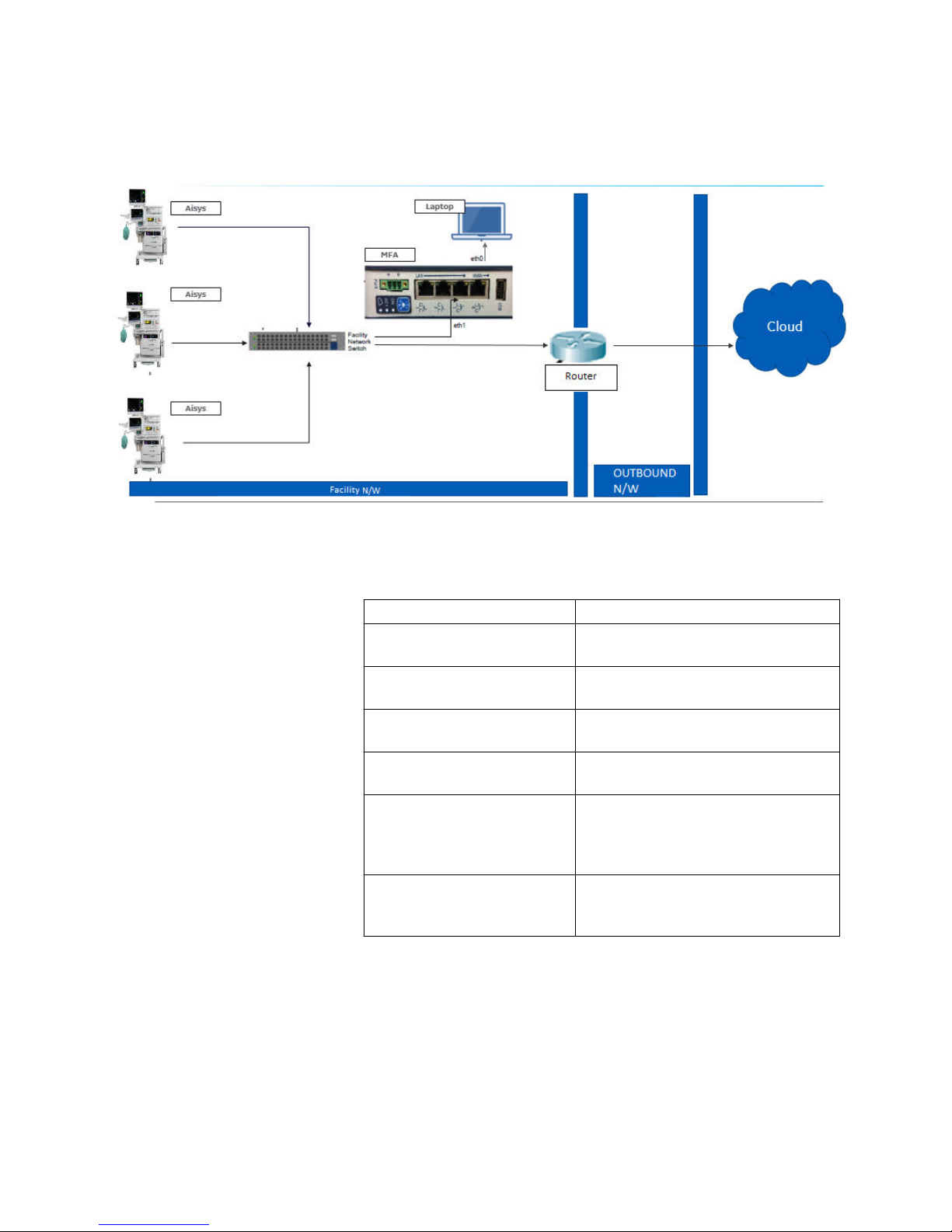
The following diagram shows the data flow in a typical facility
installation:
AC.26p.101
Figure 2 • Carestation Insights facility data flow
Component Name Description
Facility N/W Network where the Anesthesia Machines
and MFA is placed behind the router.
OUTBOUND N/W This is the Facility Network which has
access to Internet.
Aisys (software version 11 or
higher)
Anesthesia Machines connected to MFA
over MFA LAN Port.
MFA Receives data from Aisys machines and
sends data to router over LAN Port.
Router Router configured with ACL to receive
data from MFA and route it to
OUTBOUND N/W (if applicable to the
facility network).
Laptop Field engineer laptop connected to MFA
over MFA WAN Port (required only for
configuration and initial setup).
Ensure the Mini Field Agent is connected to the same facility network
to which the anesthesia machines are connected.
If a firewall or router exists in front of the MFA at the hospital
network, then confirm from the network design team or the facility IT
team that the entries mentioned in the "Configure Router ACL
Settings" is already configured.
Note
Note
42094532-001 D 02 2018
Configuring the Mini Field Agent
Perform the following procedure to install and configure the Mini
Field Agent device for use in the Carestation Insights solution.
Preparing Mini Field Agent for Boot Up
To prepare the Mini Field Agent for bootup, perform the following
steps:
The Mini Field Agent Network port has been pre-configured with the
IP address 192.168.101.2 and subnet mask of 255.255.255.0.
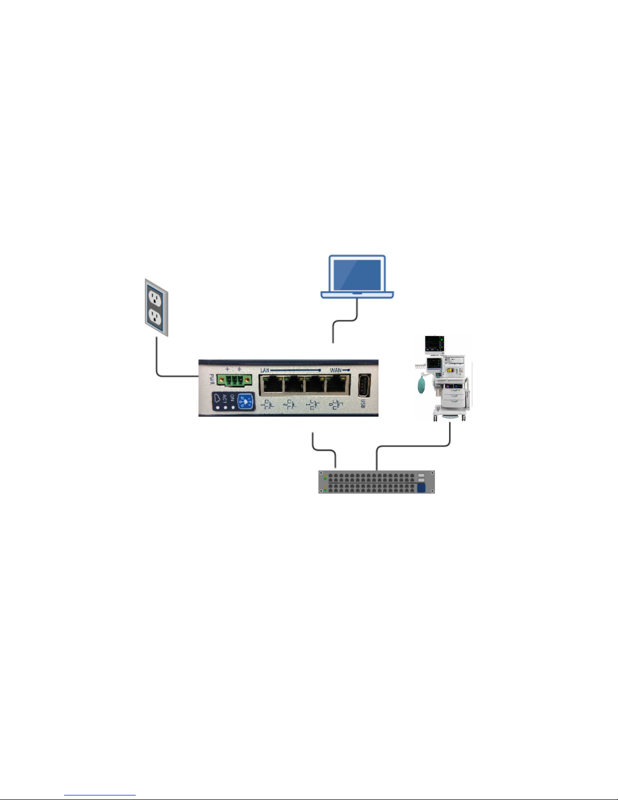
AC.26p013
Computer
eth0
eth1
Capsule
Server
Facility
Network
Switch
Power
Supply
SBX
Figure 3 • Mini Field Agent integration diagram
1. Connect the Mini Field Agent WAN Port 0 to the computer
ethernet port, using an ethernet cable.
2. Connect the Mini Field Agent LAN Port 1 to the Facility network
switch, using an ethernet cable.
3. Connect the Mini Field Agent to the power supply.
Note
2094532-001 D 02 2018 5

Configuring Computer IP Address
Configure the IP address of the wired interface of the computer as
follows:
This configuration is for a Windows 7 computer. The same procedure
can be used for other operating systems, however there might be a
slight difference in menu options.
1. Navigate to Control Panel - Network and Internet - View
network status and tasks.
2. Select Change adapter settings.
3. Right-click on Local Area Connection and select Properties. If
a security warning pop-up appears, select Yes.
4. In the Local Area Connection Properties window, double-click
on Internet Protocol Version 4 (TCP/IPv4) .
The Internet Protocol Version 4 (TCP/IPv4) Properties
window opens.
5. In the General tab, select Use the following IP address.
6. In the IP address field, enter:
•192.168.101.101
7. In the Subnet mask field, enter:
•255.255.255.0
8. Select OK.
9. Select OK to exit the Local Area Connection Properties
window.
10. Verify that the Mini Field Agent is ON.
A green LED light beside ON on the Mini Field Agent indicates
that the device is switched ON.
11. Click Start. In the Search field, enter:
• cmd
The command prompt window opens.
12. In the command prompt window, type the following and then
press Enter.
•ping 192.168.101.2
A reply as shown below indicates that the computer is
connected to the Mini Field Agent.
Note
Note
62094532-001 D 02 2018
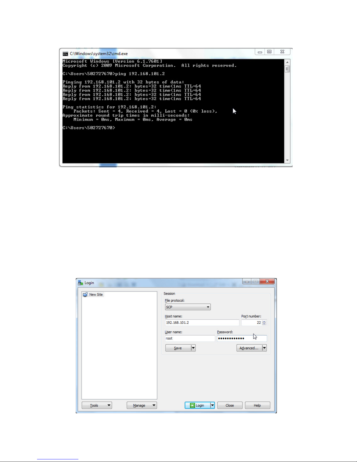
AC.26p.044
An error or timeout message indicates no communication
between the computer and Mini Field Agent.
Configuring Facility IP Address
To configure the IP address of the Mini Field Agent to connect to the
Facility Network, perform the following procedure:
1. Log into WinSCP on the computer connected with the Mini Field
Agent.
The Login window opens. Screenshot may vary depending on
the version of WinSCP used.
AC.26p.060
Note
2094532-001 D 02 2018 7

2. Select SCP in the File protocol drop-down list.
3. In the Host name field, enter:
•192.168.101.2
4. Verify that the Port number is 22. Modify if required.
5. In the User name field, enter:
•root
6. In the Password field, enter:
•MrootMfa0210
7. Select Login.
8. Once logged into WinSCP, select /<root> from the drop-down
menu, as shown in the screenshot:
AC.26p.045
9. Navigate to /etc
10. Right-click on "hosts" file and select Edit.
11. Verify that the content of the "hosts" file matches with the
content as shown in the below screenshot else update to match.
AC.26p.102
82094532-001 D 02 2018

12. Save and close the "hosts" file after verification.
13. Navigate to /etc/network
14. Right-click on "interfaces" file and select Edit.
The "interfaces" file opens as shown in the screenshot:
AC.26p.037
15. Under # eth0, Change "gateway 192.168.101.1" to "#gateway
192.168.101.1".
16. Under # eth1 change the following entries:
• "address 192.168.1.2" to "address <IP Address>"
• "netmask 255.255.255.0" to "netmask <Subnet Mask>"
• "gateway 192.168.1.1" to "post-up route add default
gw <Default Gateway> dev eth1"
See "Facility information" for the values of <IP Address>,
<Subnet Mask> and the <Default Gateway>.
After these changes, the "interfaces" file looks as shown in
the below screenshot.
The three IP addresses shown in the below screenshot
under # eth1 is only for illustration purposes. See "Facility
information" for actual addresses.
Note
2094532-001 D 02 2018 9

AC.26p.100
17. Save the close the "interfaces" file.
18. Reboot the Mini Field Agent as described in "Rebooting Mini
Field Agent".
19. Using PuTTY, perform the following:
• In the Host Name field, enter: 192.168.101.2
• Ensure port number is 22.
• Click Open.
A PuTTY Security Alert window opens.
20. Click Yes, to continue.
21. In the PuTTY window:
• Enter the Login: root
• Enter the Password: MrootMfa0210
The password must be typed in, it cannot be copy and pasted.
There is no indication of characters entered.
After typing the password, press Enter.
22. To verify that the IP address is reflected in inet addr and
netmask in Mask for eth1, enter:
•ifconfig
Important
10 2094532-001 D 02 2018
Other manuals for Mini Field Agent
1
Table of contents
Other GE Industrial PC manuals


Popular Industrial PC manuals by other brands


Dell
Dell Embedded Box PC 5000 Installation and operation manual

IBASE Technology
IBASE Technology ASB200-918 Series user manual

Lenovo
Lenovo ThinkCentre M90q Hardware Maintenance Manual

IXXAT
IXXAT Econ 100 Hardware manual

Kontron
Kontron KBox A-151-TGL user guide

AXIOMTEK
AXIOMTEK ICO500-518 Series user manual