manuals.online logo
Brands
  1. Home
  2. •
  3. Brands
  4. •
  5. Miura
  6. •
  7. Water Dispenser
  8. •
  9. Miura MS Series User manual

Miura MS Series User manual

Installation Manual
Water Softener MS Series (MS - 100U / 150U / 250U / 325U)
Check your local building and sanitation codes for installation compliance. Since Miura MS
series water softener is designed for steam boilers make-up usage, it cannot be allowed
drinking and residential usage. Installation Must Meet All State and Local Plumbing,
Electrical, Building code, Occupational Health & SafetyAct, and Regulations..
1. Installation Location
1) Select a location near the drain.
2) When installing, allow enough clearance for maintanence and
operational space.
2. Filling of Resin Tank
Water softeners require on-site resin filling of the tank. Place the resin tank at its installation location and follow the
necessary steps below.
1) Check that the inside of the resin tank is empty and clean.
2) Insert the center pipe in the resin tank. To prevent resin and gravel from entering the center pipe, plug the pipe
at the top (Figure 1)..
3) Be certain the top of center pipe is within 0 – 3/8 inch (0 - 10 mm) below
the top of the resin tank still remains (Figure 2).
[Note] Redo if the center pipe is positioned higher than the opening.
When the control valve is applied, the gravel and resin may
enter the water weed pipe if the center pipe exceeds
requirement.
4) Use a funnel to pour gravel into the tank (Figure 3)
[Note] Do not move the center pipe after gravel is poured into the tank.
5) Pour resin into the funnel to fill the tank with the resin. If the resin does not flow smoothly, use small amount of
water slowly along with the resin to be certain all resin is poured into tank (Figure 3). Gravel and resin are
pre-measured at the factory.
6) Clean the opening for any debris around the thread and sealing surface. Then remove the plug from the
center pipe.
Model Gravel CFT Resin CFT
MS-100U 0.7 3.5
MS-150U 1.4 5.3
MS-250U 2.1 8.8
MS-325U 4.9 11.5
Resin
Funnel
Water hose
A
dd water
slowly
Figure 3
Figure 1
Resin tank
Center pipe
Plug the center pipe
to prevent resin and
gravel from
entering.
Figure 2
0 – 0.39 inch
(0 - 10 mm)
WARNING
To prevent injury, the resin tank must
be installed on a foundation with
sufficient level surface so the tank does
not tip over.
Table 1
MIURA MANUFACTURING AMERICA Co., LTD.
MIURA NORTH AMERICA INC.
CONTROL NUMBER: WT-MN-006-00
3. Attaching the Control Valve
1) Apply silicone oil to resin tank thread, O-ring sealing surface, and 1 3/16 inch (3 cm) top section of the center
pipe (Figure 4).
2) Attach the tank adaptor to the resin tank. Slowly twist the adaptor until it is firmly attached (Figure 5).
[Note] Do not use seal tape for the threads.
3) Insert the gasket between the control valve and the tank adaptor.
[Note] Do not wet the gasket.
4) Attach the valve to the tank adaptor with the 5 hex bolts. Tighten evenly to secure the valve (Figure 5).
[Note] After assembly, if there is a water leak or control valve is removed, always replace the gasket.
4. Plumbing
Follow Figure 6 - 9 for connecting the inlet / outlet pipe, drainage
pipe and the brine line. The control valve and pipe size are shown
in Table 2.
1) For the inlet side setup the following: inlet valve, strainer and
1) pressure gauge.
2) The raw water pressure must be within 26 - 71 psi. If the raw
water pressure is lower than the required pressure range, use
booster pump. If higher than the pressure range, use pressure
reducing valve.
3) For outlet side, install the following: outlet valve and water
sampling port. If there is a possibility of hot water (above 104°F)
backflow, such as during condensate recovery, install check
valve also.
4) Add a bypass valve for maintenance.
5) Use 3/4 inch PVC for the drainage pipe. Do not place the pipe
5) end above the control valve. Back-pressure will build on the
5) control valve and will cause the unit to fail (Figure 7).
Tank adaptor
O-Ring
Rubber
Top distribute
r
Figure 4
Valve
socket
PVC pipe
A
ir gap
Figure 7
Table 2
1 1/2
1 1/2
3/4
Brine 3/8
Connection Size (Inch)
Raw Wate
r
Softened
Draina
g
e
WARNING
Install the inlet and outlet pipes so the negative
pressure does not build up in the pipe. Negative
pressure can cause the resin tank to deform and
break. If the tank is installed higher than the water
supply source and the softened water tank,
re-direct the water to another tank first and use a
feed pump.
WARNING
Negative pressure buildup in the drain pipe can
cause the resin tank to deform and break. Make
sure that water is released within 3.3 feet (1 m)
below the tank. Also, the back-pressure causes
the regeneration error. Check that hoses are not
deformed and their diameters have not shrunk.
Hex bolt
Gasket
Tank adapter
Figure 5
Figure 6
Drainage pipe
Bypass pipeline
Raw water
pipe
Strainer
(Included)
Inlet valve
Tee
Pressure gauge
(Included)
Bypass valve
Water sampling port
(Included)
Brine line tube
(Included)
Overflow hose
(Included)
Processed water
pipeline
Bushing
Tee
Output valve
Valve
(Included)
Bushing
Union valve assy
(Included)
6) Attach the brine line tube to the control
valve using push fit joint (Figure 8).
7) Attach the other end of brine line tube to
the valve inside of brine tank (Figure 9).
[Note] After connecting the tube tug
lightly on both ends to check if the tube
does not come off.
8) Attach the over flow hose to the drainage
hose joint and then use the hose clamp
to hold it in place.
9) All drain lines must be atmospheric.
5. Power Supply Connection
1) 120 VAC, single phase. Area must have a outlet that allows 24 hour
continuous usage by the device. ( Typical 2 W; Total 66W, 10 sec
during regeneration)
2) Attach an earth leakage circuit breaker with over-current protection.
(circuit breaker max: 5 A)
3) Plug the water softener to 120 V electrical outlet..
4) The gauge of power supply wiring must be not less than AWG18.
S811-089-0600-0
Issue of date: Apr 6, 2011
The termination output during regeneration
Regeneration for the non-voltage termination (max 3 A).
zNo. 4 – 6: not shorted during regeneration
(not shorted when water feed exist)
zNo. 4 – 5: shorted during regeneration
(shorted when there is no water feed)
Push fit joint
Brine line tube
Figure 8
WARNING
・Failure to use specified power supply
can cause fire.
・To prevent shock, attach an earth
leakage circuit breaker to the unit.
・To prevent fire, use specified gauge
size for the power supply wires.
・To prevent shock or malfunction,
grounding is necessary.
Figure 9
Overflow hose
Hose clamp
Brine valve
Brine line tube

This manual suits for next models

4

Other Miura Water Dispenser manuals

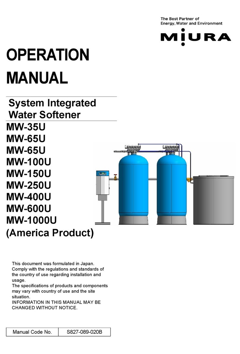
Miura MW-35U User manual

Miura

Miura MW-35U User manual

Miura MS Series User manual

Miura

Miura MS Series User manual

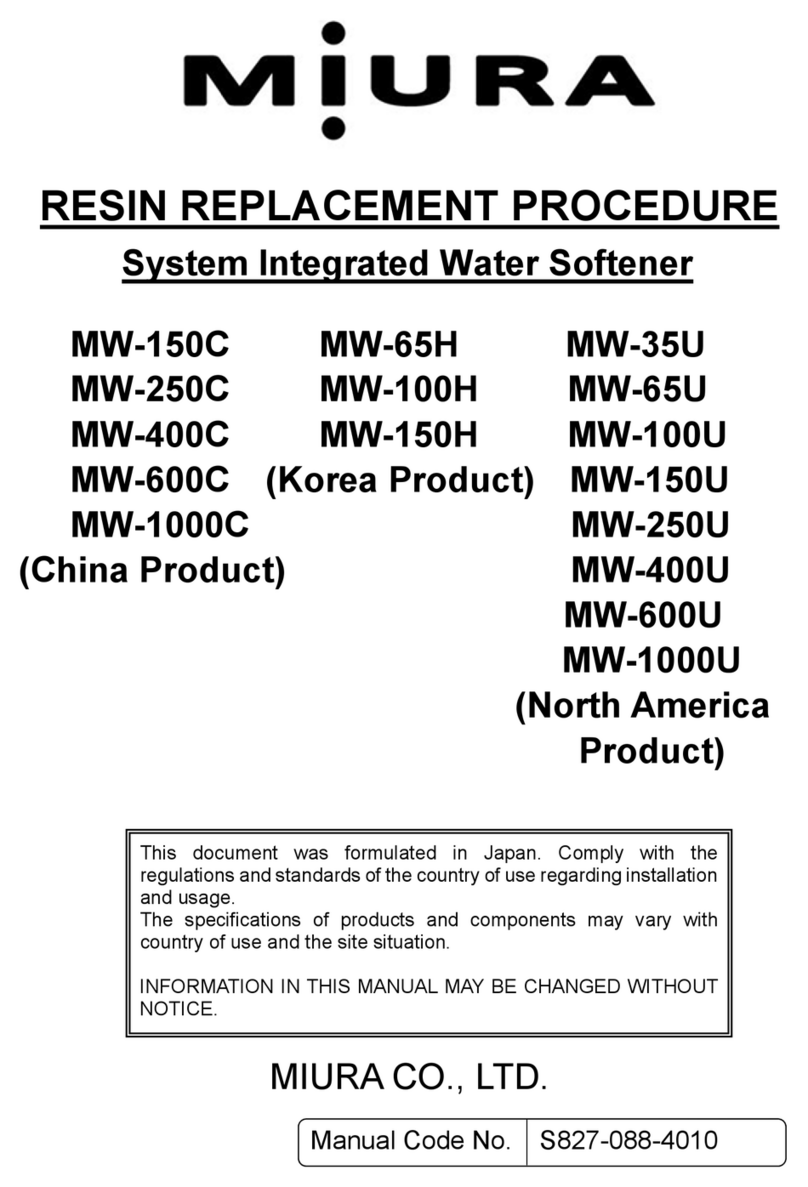
Miura MW-150C Use and care manual

Miura

Miura MW-150C Use and care manual

Miura MW-35U User manual

Miura

Miura MW-35U User manual

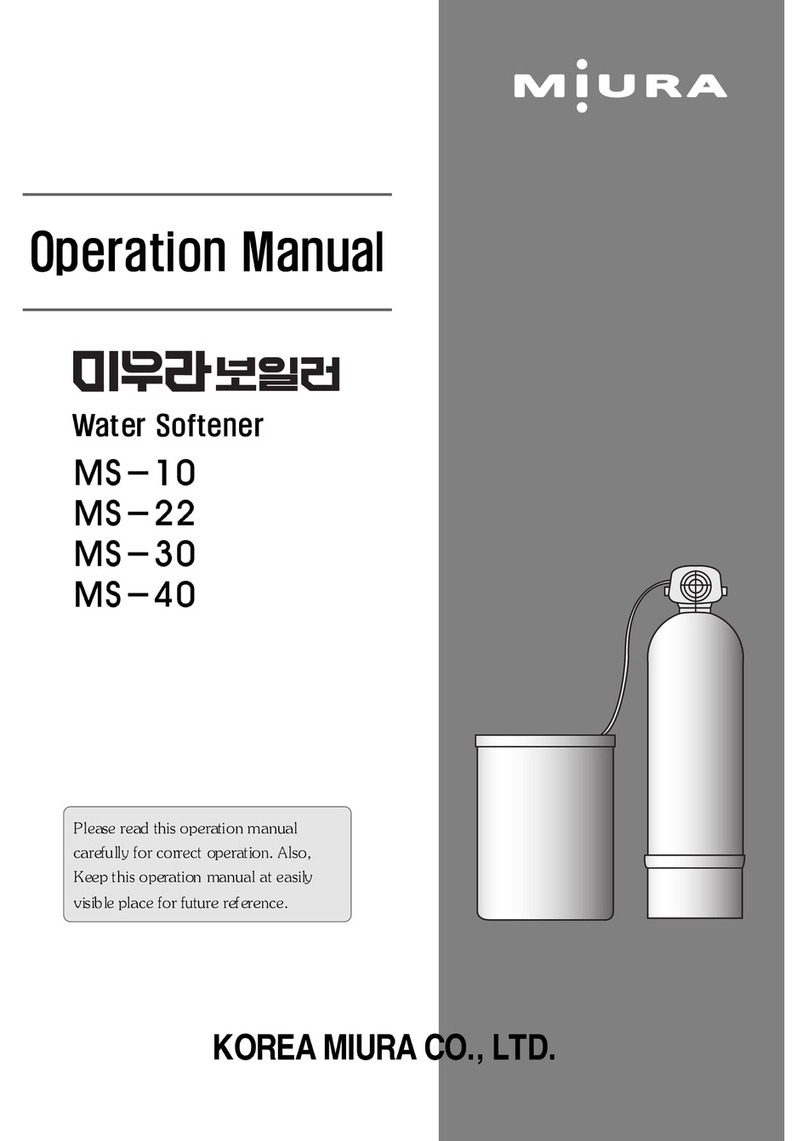
Miura MS-10 User manual

Miura

Miura MS-10 User manual

Popular Water Dispenser manuals by other brands

Krystal Pure KS15HE operating instructions

Krystal Pure

Krystal Pure KS15HE operating instructions

Daikin EWWP045KAW1M Operation manual

Daikin

Daikin EWWP045KAW1M Operation manual

Elkay EMABF8TL Series Installation, care & use manual

Elkay

Elkay EMABF8TL Series Installation, care & use manual

resideo Braukmann KS30E-30 installation instructions

resideo

resideo Braukmann KS30E-30 installation instructions

BWT AQA smart Installation and operating manual

BWT

BWT AQA smart Installation and operating manual

WaterLogic WL400 Series Installation procedures

WaterLogic

WaterLogic WL400 Series Installation procedures

Youngwoo Waterline Portable H2 Server User manual & warranty

Youngwoo Waterline

Youngwoo Waterline Portable H2 Server User manual & warranty

Everpure CGT-20S Specification sheet

Everpure

Everpure CGT-20S Specification sheet

Elkay VRC Series Installation, care & use manual

Elkay

Elkay VRC Series Installation, care & use manual

AQUA-LITY A/C Installation, use and maintenance handbook

AQUA-LITY

AQUA-LITY A/C Installation, use and maintenance handbook

Puretec Softrol E3 user guide

Puretec

Puretec Softrol E3 user guide

Pro-Aqua Travel Series owner's manual

Pro-Aqua

Pro-Aqua Travel Series owner's manual

German pool IWD-102 user manual

German pool

German pool IWD-102 user manual

pilotair ACT 180T User’s Maintenance & Spare Parts Manual

pilotair

pilotair ACT 180T User’s Maintenance & Spare Parts Manual

Aqua PRO WaterPro Service manual

Aqua PRO

Aqua PRO WaterPro Service manual

OCEANAIRE OWC1811QC Engineering, installation and service manual

OCEANAIRE

OCEANAIRE OWC1811QC Engineering, installation and service manual

ThePondguy SolidFlo 600 Installation & maintenance

ThePondguy

ThePondguy SolidFlo 600 Installation & maintenance

Tier1 WS-165-150-BLK owner's manual

Tier1

Tier1 WS-165-150-BLK owner's manual

manuals.online logo
manuals.online logoBrands
  • About & Mission
  • Contact us
  • Privacy Policy
  • Terms and Conditions

Copyright 2025 Manuals.Online. All Rights Reserved.