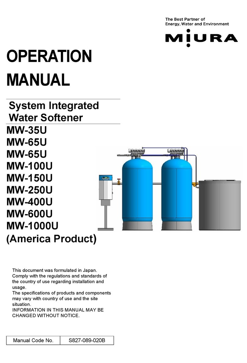
Miura MW-35U User manual

MAINTENANCE MANUAL
SYSTEM INTEGRATED WATER SOFTENER
MW-35U - 1000U
(America Product)
MIURA CO., LTD.
This document was formulated in Japan. Comply with the
regulations and standards of the country of use regarding
installation and usage.
The specifications of products and components may vary
with country of use and the site situation.
INFORMATION IN THIS MANUAL MAY BE CHANGED
WITHOUT NOTICE.
Manual Code No. S827-089-0917

MIURA_CONFIDENTIAL
No. S827-089-0917
- Table of Contents -
1. System Construction and Description of Parts ..........................................................1
1.1 Overview ..................................................................................................................................1
1.1.1 MW-35U, MW-65U ...........................................................................................................1
1.1.2 MW-100U, MW-150U, MW-250U, and MW-400U ...........................................................2
1.1.3 MW-600U and MW-1000U...............................................................................................3
1.2 Control Box –– Internal Diagram .............................................................................................5
1.2.1 MW-35U, MW-65U, MW-100U, MW-150U, MW-250U, and MW-400U ..........................5
1.2.2 MW-600U and MW-1000U...............................................................................................6
1.3 Names and Functions of the Control Panel.............................................................................7
1.4 Names and Functions of Operated Parts on CPU Board .......................................................8
1.5 Flow Sheet .............................................................................................................................11
1.5.1 MW-35U, MW-65U .........................................................................................................11
1.5.2 MW-100U,MW-150U, MW-250U, and MW-400U ..........................................................12
1.5.3 MW-600U and MW-1000U.............................................................................................13
2. LCD Display and Settings........................................................................................14
2.1 Operation and Display Flowchart ..........................................................................................14
2.2 Details of Each Mode.............................................................................................................15
2.2.1 Display when Powering Up ............................................................................................15
2.2.2 User Mode......................................................................................................................15
2.2.3 Setting Modes ................................................................................................................17
2.2.4 I/O Modes.......................................................................................................................25
2.2.5 Alarm History Mode........................................................................................................26
2.2.6 Management Data Mode................................................................................................26
2.2.7 Maintenance Manual Regeneration Mode.....................................................................27
2.2.8 Control Valve Position Manual Reset Mode ..................................................................27
3. Control Overview.....................................................................................................28
3.1 Regeneration Modes .............................................................................................................28
3.1.1 Alternating regeneration based on flow rate..................................................................28
3.1.2 Alternating periodic regeneration ...................................................................................28
3.1.3 Single-unit regeneration based on time and flow rate ...................................................28
3.1.4 Single-unit periodic regeneration ...................................................................................29
3.2 Manual Regeneration ............................................................................................................29
3.2.1 User Manual Regeneration ............................................................................................29
3.2.2 Maintenance Manual Regeneration...............................................................................29
3.3 Regeneration Process Control ..............................................................................................30
3.3.1 Service Process .............................................................................................................32
3.3.2 Service → Backwash Process Transition ......................................................................33
7
7
7
7
7
7

MIURA_CONFIDENTIAL
No. S827-089-0917
3.3.3 Backwash Process.........................................................................................................34
3.3.4 Backwash → Regeneration Standby Process Transition ..............................................35
3.3.5 Regeneration Standby Process .....................................................................................36
3.3.6 Regeneration Standby → Brine Process Transition ......................................................37
3.3.7 Brine Process .................................................................................................................38
3.3.8 Brine → Slow Rinse Process Transition ........................................................................39
3.3.9 Slow Rinse Process .......................................................................................................40
3.3.10 Slow Rinse → Fast Rinse or Brine 2 Process Transition...............................................41
3.3.11 Brine 2 Process ..............................................................................................................42
3.3.12 Brine 2 → Slow Rinse 2 Process Transition ..................................................................42
3.3.13 Slow Rinse 2 Process ....................................................................................................43
3.3.14 Slow Rinse 2 → Fast Rinse Process Transition ............................................................43
3.3.15 Fast Rinse Process ........................................................................................................44
3.3.16 Fast Rinse → Refill Process Transition .........................................................................45
3.3.17 Refill Process .................................................................................................................46
3.3.18 Refill → Service Standby Process Transition ................................................................47
3.3.19 Service Standby Process...............................................................................................48
3.3.20 Service Standby → Service Process Transition ............................................................49
3.3.21 Unit Failure Process.......................................................................................................50
3.3.22 Control Valve Position Reset Process ...........................................................................53
3.4 Regeneration Control Data Table ..........................................................................................54
3.5 Control when Regeneration Ends..........................................................................................55
3.5.1 Residual Capacity Reset Processing.............................................................................55
3.5.2 Regeneration Interlock Time Processing .......................................................................56
3.6 Coordinated Control with Colormetry ....................................................................................56
3.6.1 Backup Control with Colormetry (Hardness Leakage Regeneration) ...........................56
3.6.2 Automatic Calculation and Control of Amount of Water Sampling with Colormetry......58
for Raw Water Hardness ............................................................................................................58
4. MOM Communications ............................................................................................59
4.1 Saving and Loading the Settings...........................................................................................59
4.2 Guide to Screens ...................................................................................................................61
4.2.1 Realtime Monitor Screen................................................................................................61
4.2.2 Monitor Data Screen ......................................................................................................64
4.2.3 Regeneration History Data Screen ................................................................................66
4.2.4 Alarm History Data Screen.............................................................................................69
5. Guide to Warnings, Cautions, and Notices ..............................................................72

MIURA_CONFIDENTIAL
No. S827-089-0917
1
1. System Construction and Description of Parts
1.1 Overview
1.1.1 MW-35U, MW-65U
Control box
Brine tank
Control panel
Pressure gauge
Pressure switch
Water sampling port
Inlet valve
(procured on site
Pressure reducing valve
*Installed when the raw
water pressure is high
Strainer
Water flowmeter
Flow control valve
No. 2 unit
Ggou
No. 1 unit
Ggou
Bypass valve assembly
Figure 1.1: System Overview (MW-35U, MW-65U)
Control valve
Front view
Rear view
Softened
water outlet
Raw water
inlet
Regeneration
drain outlet
7
7
7

MIURA_CONFIDENTIAL
No. S827-089-0917
2
1.1.2 MW-100U, MW-150U, MW-250U, and MW-400U
※Piping shape is slightly different between MW-100U and MW-150 to MW-400U.
※Resin tank shape is slightly different between MW-100U/150U and MW-250/400U.
Figure 1.2: System Overview (MW-100U, MW-150U, MW-250U, and MW-400U)
Control valve
Control panel
Brine tank
No. 1 unit
Ggou
No. 2 unit
Ggou
Front view
Control box
Pressure
gauge
Water
sampling
port
Pressure switch
Water
flowmeter
Inlet
valve
(procured
on site)
Flow
control
valve
Raw water
inlet
Softened
water outlet
Pressure reducing
valve
*Installed when
the raw water
pressure is high
Strainer
Regeneration
drain outlet
Rear view
7
7
7
7
Other manuals for MW-35U
1
This manual suits for next models
7
Table of contents
Other Miura Water Dispenser manuals
Popular Water Dispenser manuals by other brands

IBC Water
IBC Water AST0715MP-960 Installation & operating instructions

Lancaster Water Treatment
Lancaster Water Treatment X FACTOR LX15 Series Installation, operating and service manual

Elkay
Elkay EMABF8 Series Installation & use manual

Oasis
Oasis Osmosis Home installation manual

Monarch Water
Monarch Water ULTIMATE MINI AQUA HE install guide

Haier
Haier HLM-109B instruction manual