5) Insert the drain hose (inner diameter of ø12mm
the longer one) to the drain port of control valve
and use the hose clamp to hold it in place (Figure
2).
6) Attach the brine line tube (white 3/8 inch) to the
control valve and the brine line valve using push fit
joint(Figures 2 & 3).
[Note] To remove tube after installation,
Compresspush.
7) Attach the overflow hose (inner diameter of ø12
mm, the shorter one) to the adapter on the brine
tank wall, then use the hose clamp to hold it in
place
8) All drain lines must be atmospheric.
3. Filling of Resin Tank
Water softeners require on-site resin filling of the tank. Place the resin tank at its installation location
and follow the necessary steps below.
1) Check that the inside of resin tank is empty and clean.
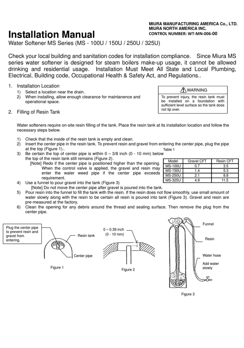
2) Insert the center pipe in the resin tank. To prevent resin and gravel from entering the center pipe, plug the
pipe at the top. (Figure 5)
3) Be certain the top of center pipe is 0 – 3/8 inch (0 - 10 mm) below the top of the resin tank still remains
(Figure 7).
[Note] Redo this process if the center pipe is positioned higher than the opening. When the control
valve is applied the silica and resin may enter the water feed pipe if the center pipe exceeds
requirement.
Warning
Negative pressure buildup in the drain pipe
can cause the resin tank to deform and break.
Make sure that water is released not more
than 3 feet below the tank. Also, the
back-pressure causes the regeneration error.
Check that hoses are not deformed and their
diameters have not shrunk.
WARNING
Inlet and outlet pipes must be installed such
that negative pressure does not build up in the
pipe. Negative pressure can cause the resin
tank to deform and break. If the resin tank
elevation is higher than the water supply
source and the feed water tank, re-direct the
water to another tank first and supply a
Figure 2. Control valve assembly
Drain hose ø12mm x ø16mm
(included)
Hose clamp
Bypass valve
Adapter clip
Tapping screw
Push fit joint
Drain port
Overflow hose
Hose clamp
Brine valve
Brine line tube
(3/8 inch)
Figure 3. Brine tank
Brine tube (included)
Overflow hose
Hose clamp
Brine valve
Brine line tube
(3/8 inch)
Come from
control valve


