Miura MW-150C Use and care manual

RESIN REPLACEMENT PROCEDURE
System Integrated Water Softener
MW-150C MW-65H MW-35U
MW-250C MW-100H MW-65U
MW-400C MW-150H MW-100U
MW-600C (Korea Product) MW-150U
MW-1000C MW-250U
(China Product) MW-400U
MW-600U
MW-1000U
(NorthAmerica
Product)
MIURA CO., LTD.
This document was formulated in Japan. Comply with the
regulations and standards of the country of use regarding installation
and usage.
The specifications of products and components may vary with
country of use and the site situation.
INFORMATION IN THIS MANUAL MAY BE CHANGED WITHOUT
NOTICE.
Manual Code No. S827-088-4010

MIURA_CONFIDENTIAL
Document No.: S827-088-4010
○This material explains the exchange procedure of ion exchange resin of system water softener
MW type (hereinafter referred to as this machine). When doing the resin replacement work of this
machine, please carry out the work correctly based on this material.
- Table of Contents -
1. Required parts .........................................................................................................1
2. Tools and protective equipment ............................................................................2
3. Operational procedure............................................................................................3
3-1 Resin replacement for small MW................................................................................................. 4
3-1-1 Removal of control valve ...................................................................................................... 4
3-1-2 Drawing out resin and gravel ................................................................................................ 6
3-1-3 Check Collecting pipe,Resin tank,O-ring. ............................................................................. 8
3-1-4 Filling with resin and gravel .................................................................................................. 8
3-1-5 Reassembly of equipment .................................................................................................... 9
3-1-6 Procedures after replacement ............................................................................................ 10
3-1-7 Resin replacement on the other unit and procedures after replacement ............................ 11
3-2 Resin replacement for middle MW ............................................................................................ 12
3-2-1 Removal of control valve .................................................................................................... 12
3-2-2 Drawing out resin and gravel .............................................................................................. 14
3-2-3 Checking the collecting pipe, resin tank, and O-rings......................................................... 15
3-2-4 Feed in gravel and resin. .................................................................................................... 16
3-2-5 Reassembly of equipment .................................................................................................. 17
3-2-6 Procedures after replacement ............................................................................................ 18
3-2-7 Resin replacement on the other unit and procedures after replacement ............................ 19
3-3 Resin replacement for large MW ............................................................................................... 20
3-3-1 Stopping the water flow in the equipment........................................................................... 20
3-3-2 Opening of the resin tank.................................................................................................... 21
3-3-3 Checking resin tank and O-rings ........................................................................................ 22
3-3-4 Drawing out resin and gravel .............................................................................................. 23
3-3-5 Filling with gravel and resin ................................................................................................ 23
3-3-6 Reassembly of equipment .................................................................................................. 24
3-3-7 Procedures after replacement ............................................................................................ 25
3-3-8 Resin replacement on the other unit and procedures after replacement ............................ 26

MIURA_CONFIDENTIAL
Document No.: S827-088-4010
1
1.
Required parts
●Resin, Gravel
Note:When replacing the resin for both unit 1 and unit 2, the amount required is double the amount
shown in the table below.
Table1. Amount of resin and gravel required for per unit(per resin tank)【CHINA】
Table2. Amount of resin and gravel required for per unit(per resin tank)【AMERICA】
MW-35U MW-65U MW-100U MW-150U MW-250U MW-400U MW-600U MW-1000U
5L 9L 12L 2 4 6.5 4 6.5
Resin
amount
(bag)
Brand:Pure Resin PC004
Brand:DOW(R&H) C101Na
1bag=25L=0.883CFT
1.4 2.6 4 6 101624 40
Model
Gravel amount(bag※)
1 bag=50 lbs
Note1:The Unit of amount of gravel for MW-35,65,100U is litre.
Table3. Amount of resin and gravel required for per unit(per resin tank)【KOREA】
Model MW-65H MW-100H MW-150H
Gravel amout(L) 9 12 30
Resin amount(L) 65 100 150
●Collecting pipe assembly and tank adapter assembly.
Note: Only for MW-65H to 150H, 150C to 400C, and 35U to 400U.
After long use, the collecting section (bottom section) of the collecting pipe
assembly and tank adapter assembly may be clogged at the net or slit or
broken by the resin being forced into the gravel layer during the last resin
replacement. Therefore, replace the collecting section together with the resin
due to a potential breakage or blockage of the net.
Note: When such breakage occurs, the resin may spill to the secondary side.
Note: Refer to the parts catalog for the parts code.
Figure 1. Collecting pipe ASSY
Collecting pipe ASSY
Model MW-150C MW-250C MW-400C MW-600C MW-1000C
Gravel amount(bag)
1bag=25kg
2
(50kg)
3.5
(87.5kg)
6
(150kg)
3.5
(87.5kg)
6
(150kg)
Resin amount(bag)
1bag=20kg
7
(140kg)
11
(220kg)
18
(360kg)
26
(520kg)
44
(880kg)

MIURA_CONFIDENTIAL
Document No.: S827-088-4010
2
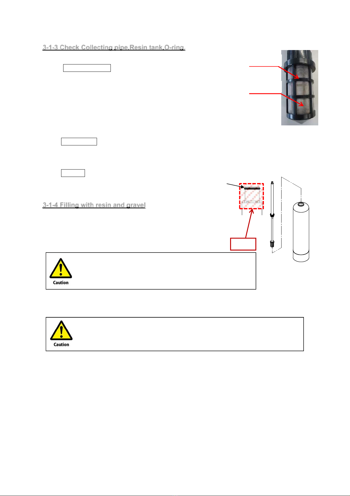
●Seal parts(If necessary)
Replace the seal parts such as O-rings together, if damage or deterioration is found.
The seal parts that could require replacement in this work are shown below.
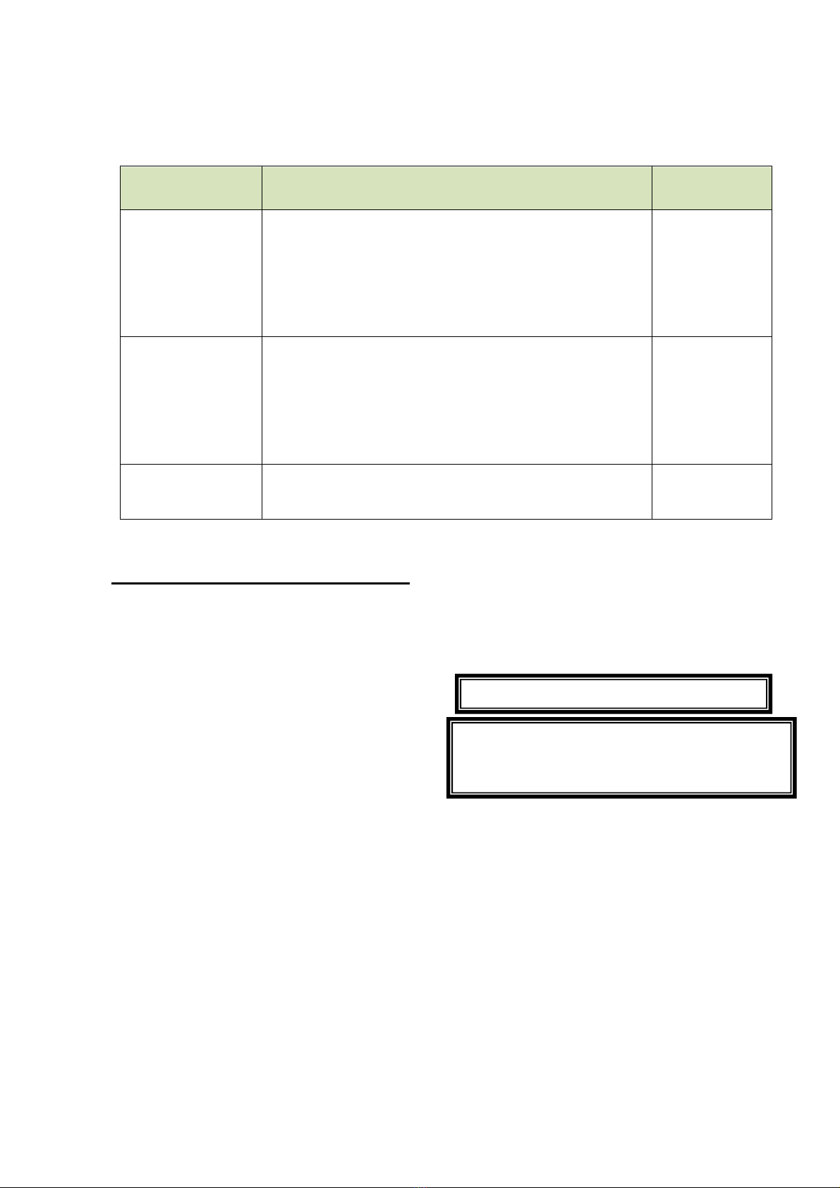
Table 4. Seal parts with possibility of replacement
Model Seal parts with possibility of replacement Reference
page
MW-35U,65U
【Connection part of resin tank and control valve】
・O-ring Old JIS W1516 AN6227(Material:NBR)
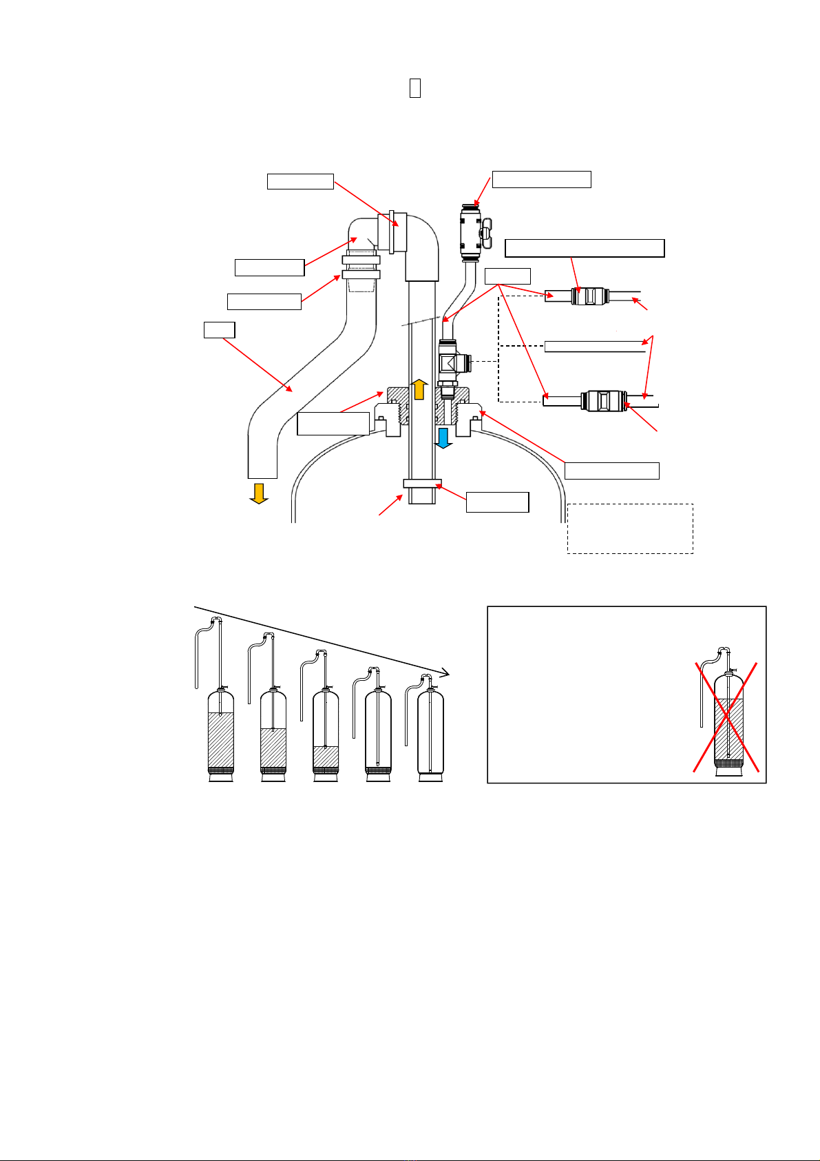
【Tip of connection pipe ASSY(Refer to P9 figure)】
・O-ring P21(Material:NBR)
【Connection part of bypass valve and control valve】
・O-ring D=23.5mm W=2.5mm(Material:NBR)
P4,8
MW-65H~150H
MW-150C~400C
MW-100U~400U
【Connection part of resin tank and tank adaptor】
・O-ring P105(Material:NBR)
【Connection part of tank adaptor and control valve】
・O-ring AS568-349(Material:NBR)
・O-ring P65(Material:NBR)
・Backup ring for P65
P15
MW-600C/U,
1000C/U
【Connection part of resin tank】
・O-ring P185(Material:NBR) P19
Note: Refer to the parts catalog for the parts code.
2. Tools and protective equipment
●Tools, parts
・PVC pipe 2m-2.5m about φ32 (For leveling the gravel layer after filling the gravel)
・Tank adaptor spanner (For MW-65H-150H,150C-400C,100U-400U)
CHINA, AMERICA・・・ Use the tool provided with the product. Alternatively, prepare your own tool.
KOREA・・・Japan parts code:S827-008-6101-6
• Funnel for filling the resin
For MW-35U,65U
Japan parts code:S827-001-7700-4
For MW-65H-150H, 150C-400C, 00U-400U
Japan parts code:S827-001-7800-4
・MW resin replacement kit S427-920-0010-7 (For MW-65H-150H,150C-400C,100U-400U)
*The following parts are required separately. (refer to P7)
JIS standard PVC pipe:Pipe TS VP25X2000L PVC(J140-125-2000-0)
φ16-φ12 conversion tube fitting: Different diameter tube fitting(SA27-000-0490-0)
・Resin receiving container (Tank etc.), Soil bag ,Water receiving container (Poly beaker etc.)
・Hose(If drain the resin by siphon),Commercial vacuum cleaner (Both dry and humid),Bus pump etc.
・Measuring cup (2L) ・Silicone oil ( or grease)
・Standard tool set
●Wearing of protective equipment
Depending on the work, wear a safety hat, safety glasses, safety mask, safety shoes, leather gloves,
etc.
When performing work in a high place, wear a safety belt to prevent a fall.
If necessary, arrange the funnel for filling the resin.
Resin replacement is possible without the resin
replacement kit. Work efficiency can be improved by using
resin replacement kit. Please arrange as necessary.

MIURA_CONFIDENTIAL
Document No.: S827-088-4010
3
3.
Operational procedure
Note:
Although you can pass water in the other unit during the replacement work, pay attention to the
residual capacity of the unit passing water.
• If only one of the units has a reduced residual capacity, first replace the resin of the unit with
the reduced residual capacity.
• If both units have a reduced residual capacity, replace the resin after recovering the residual
capacity by a manual regeneration.
The details of the work depend on the equipment capacity.
Classification CHINA・AMERICA
(High hardness area) KOREA Work reference page
Small Model MW-35U
MW-65U
P4
3-1 Replace the resin of the
small MW
Middle
Model
MW-100U
MW-150C/U
MW-250C/U
MW-400C/U
MW-65H
MW-100H
MW-150H
P12
3-2 Replace the resin of the
middle MW
Large Model MW-600C/U
MW-1000C/U
P20
3-3 Replace the resin of the
large MW
Replace the resin when no abnormality is occurring in the equipment and the
equipment state is in service process or service standby process.
Do not climb or place your foot on the resin tank. Doing so may cause a serious injury
due to a fall/tumble.
Prepare a working floor using a scaffold, etc. and wear a safety belt and other protective
gear to prevent a fall.

MIURA_CONFIDENTIAL
Document No.: S827-088-4010
4
3-1 Resin replacement for small MW
This section provides instructions on the resin replacement for a small MW.
3-1-1 Removal of control valve
(1) In the maintenance manual regeneration mode, set the unit on which the replacement is
performed to the backwash process in order to release the water pressure inside the resin tank
as well as to perform air bleeding and discharge of colored water after the resin replacement.
Note: For the method of maintenance manual regeneration, see the Start-up Operation
Manual and Inspection Manual for each country.
(2) Confirm that the equipment is in the backwash process and turn OFF the MW (main power) to
prevent the process from changing during the resin replacement and for safety reasons.
(3) Operate the bypass valve of the unit on which the replacement is performed and bring the unit
to the bypass state. (Figure 2)
Note: When the unit in service is set to the bypass state, raw water is supplied to the
secondary side.Pay attention to the unit state.
(4) Close the maintenance valve on the ejector line. (Figure 2)
(5) Remove the bypass valve of the unit on which the replacement is performed.
Figure2. Bypass valve operation (MW-35U,65U)
Figure3. How to remove the bypass valve
Some water will come out. Catch it with a bucket, etc.
Bypass valve handle
Tapping screw
Adaptor clip
No.1 unit
Maintenance valve
Open →Close
O-ring
D=23.5mm W=2.5mm
No.2 unit
Maintenance valve
Open →Close
Ejector line

MIURA_CONFIDENTIAL
Document No.: S827-088-4010
5
(6) Disconnect the tubing and wiring of the unit on which the replacement is performed.
◆Tube piping
Brine line・・・ Tube connecting the brine tank and the main unit
Tube connecting the unit 1 and unit 2 control valves
Ejector line・・・ Tube connecting the maintenance and control valves
Drain hose・・・ Hose connected to the drain port of the control valve
◆WIRING
Remove the control valve cover and disconnect the wiring.
Note: When disconnecting the connector of
the wiring, press and release the lock of the
connector. Pulling the connector by force
may cause a breakage.
Figure 5. Wiring to the control valve
Actuator wiring
Brine flowmeter wiring
(Only No.1 unit)
Screws to secure the control valve cover
(M4×10)
Figure 4. Tubing to the control valve

MIURA_CONFIDENTIAL
Document No.: S827-088-4010
6
(7) Remove the control valve and the collecting pipe of the unit on which the replacement is
performed.
Note: If the control valve section has not been removed since the
manufacture, shipment, or installation, mark the valve body
and the resin tank before removing the valve. (Refer to 3-1-
5)
Note: If it is unclear whether the control valve section has been
previously removed, mark the valve body and the resin tank
during the installation of the control valve after filling the
resin. (Refer to 3-1-5)
3-1-2 Drawing out resin and gravel
(1) Remove the resin and gravel from the resin tank.
(2) After the resin and gravel removal, drain the water inside the resin tank as well.
<Removal method>
The following methods are available. Method 1 is recommended for a large amount of resin.
1. Use vacume
・By external contractor
・Commercial vacuum cleaner
(Strong things that water and sand can aspirate)
2. Use siphon (Refer to figure 7)
While the hose is filled with water, stop the end
on one side and insert the end on the other side
into the resin tank. The resin can be siphoned out
by lowering and releasing the stopped end. Use
another hose to supply water into the resin tank
while siphoning out the resin.
3. Use bath pump
A commercial bath pump may be used. Place a bath pump inside the resin tank and pump
the resin and gravel out of the resin tank. The pumping should be performed while supplying
water to the resin tank.
4. Use resin replacement kit
<Resin replacement kit>
・Supply water in the resin tank and pump the
resin and gravel out of the resin tank by the
force of water. (Refer to figure 8)
・Receive resin and gravel with container or soil
bag etc.
Figure 6. Removal of control valve
Figure7. Using siphon
Refill
Figure8. Principle of resin replacement kit

MIURA_CONFIDENTIAL
Document No.: S827-088-4010
7
a) Set the resin replacement kit(Parts of notation are included in the resin replacement kit.)
*PVC pipe and conversion tube fitting are not included in the kit.
VP 25 pipe of Japan JIS standard is required for PVC pipes.
*Please confirm that there is space for the length of PVC pipe in the top of the resin tank.
b) Refill water into the resin tank from the ejector line and discharge resin /gravel.
· Please gradually insert so that the tip of the PVC pipe comes near the top surface of
the resin.
· When opening the closed maintenance valve, water is replenished into the resin tank from
the ejector line tube.
・As water and resin are discharged from the hose, please receive it with resin receiving
container or soil bag etc.
· In case of clogging, please stop the replenishment water, open the pressure release
valve and remove the pressure.
c) After discharging the resin/gravel, please drain water from the resin tank with siphon.
· Supply water is stopped (maintenance valve closed), water is drained by siphon when
opening pressure release valve.
If you insert the PVC pipe all the way in,
you may clog resin or gravel
into hose or PVC pipe.
In case of clogging, please be
sure to install a hose band for
preventing removal, as the PVC
pipes may come off. Please do not
leave the place while working.
Hose nipple
Hose (Open the end to
the atmosphere)
Hose band x 2
PVC pipe VP25X2500 (field arrangement)
(Please tighten the hose band to 5 cm from the tip to preven
t
it from coming off)
Conversion adapter
(Unnecessary for MW - 35U / 65U)
Pressure relief valve
(Used for depressurizing at clogging:
Closed when removing resin)
Conversion tube fitting [φ3/8 - φ12]
Ejector line tube is a tube
connected to a closed
maintenance valve.
MW-35U/65U
φ12 tube
Faucet elbow
Note) Please adhere with PVC pipe
In the case of no adhesion, there is
a possibility that the faucet elbow
will disengage and the resin will
blow out
Resin exchange
adapter
Hose band
Ejector line tube
(MW body)
MW-35U/65U
φ3/8(refer to figure2.P4)
φ16(refer to
figure 15,16.P12)
φ12(refer to
figure 15,16.P12)
Conversion tube fitting[φ12 - φ16]
(field arrangment)
MW-65H~150H
MW-150C
MW-100U/150U
M
W
-250C/400C
MW-250U/400U
Figure9.How to use resin replacement kit-1
Figure10.How to use resin replacement kit-2

MIURA_CONFIDENTIAL
Document No.: S827-088-4010
8
3-1-3 Check Collecting pipe,Resin tank,O-ring.
Check collecting pipe and resin and O-ring.
Collecting pipe
• Check that the pipe is not deformed.
• Check that there is no cracking or deformation in the mesh
or slit of the distributor and there is no peeling off of the net
from the plastic part.
• If necessary, clean the net section, etc.
• Check that there is no detachment of adhesion or welding.
Resin tank
• Check that there is no damage or dent on the sealing surface of the resin tank (O-ring
contact area).
O-ring
• Check that there is no damage or cracking.
3-1-4 Filling with resin and gravel
(1) Insert the collecting pipe assembly into the resin tank.
Insert a new collecting pipe assembly instead of the removed one.
Cover the collecting pipe with gummed tape, etc. so that
the resin or gravel does not enter the pipe.
(2) Use a funnel to fill the resin tank with gravel first and then with the resin. (Refer to Tables 1, 2,
and 3 for the amount to be filled)
After filling the tank, use a PVC pipe, etc. to level the top surface of the gravel
layer.
Insert the collecting pipe assembly to the resin tank again before
filling the tank with gravel. If you insert the collecting pipe assembly
after filling the tank with gravel, the collecting pipe may be broken.
Plastic
Mesh
Figure11. Distributor
Figure 12. Installation of
collecting pipe
Cover.
O-ring

MIURA_CONFIDENTIAL
Document No.: S827-088-4010
9
• Pay attention during filling so that the collecting pipe is positioned in the center of the opening of
the resin tank.(A tilt of the pipe toward one side makes the installation of the control valve and the
tank adapter difficult.)
• When the filling is completed, remove the cover attached on the collecting pipe.
3-1-5 Reassembly of equipment
If the valve body and the resin tank are marked in “3-1-1 Removal of control valve”-(7), install the
control valve using the marked position as a reference.
If the marking is not performed, follow the procedures below to prevent overtightening during the
installation of the control valve.
(1) With the O-ring removed from the valve body, provisionally assemble the valve on the resin
tank.(Be careful not to damage the valve body when removing the O-ring.)
(2) Mark the valve body and the resin tank where their end faces are in contact as shown in the figure
below.
Marking example
(3) Install the O-ring on the valve body.
(4) Check that silicone oil is applied to the O-ring section in the top part of the collecting pipe.
(5) Check that the O-ring is installed on the bottom of the control valve and silicone oil is applied.
After filling the tank with gravel, if you significantly move the collecting pipe, the gravel enters under
the collecting pipe and the pipe may be crushed during the installation of the control valve. If the
collecting pipe is crushed, the pipe may be broken and the gravel or resin could enter the water supply
line.
Figure 13. Cautionary notes for filling
NG tilt
Layer not smooth
- not acceptable
Smooth Layer
- OK
17~27mm
Screw the valve body into the resin tank until no
gap remains between their end faces. Perform
the marking as a reference to prevent screwing
them too far.
Marking

MIURA_CONFIDENTIAL
Document No.: S827-088-4010
10
(6) Connect the control valve with the resin tank. Pay attention to the tilt and install the control valve
using the marking position as a reference.
Note
• Do not use sealing tape for the screw section.
• Do not apply silicone oil to the screw section.
(7) Connect the tubing, wiring, and bypass valve assembly.
3-1-6 Procedures after replacement
(1) Open the maintenance valve on the ejector line.
(2) Return the replaced unit from the bypass state to the water service state.
Note: Refer to Figure 2 for the valve operations.
Note: When filling the resin tank with water, operate the valve gradually and supply the raw water
slowly until the air is bled.
Note.Check for water leakage from the connection sections.
Maintain the backwash process for several minutes to drain the air and colored water out of
the resin tank.
(3) Turn ON the MW.
O ring on tip of collecting pipe:
P21
O-ring on the bottom of the control valve:
Old JIS W1516 AN6227
Figure 14. Installation of control valve
Since the control valve is set to the position for the backwash process, the valve
operations start backwash.

MIURA_CONFIDENTIAL
Document No.: S827-088-4010
11
(4) In the maintenance manual regeneration mode, move stepwise the unit on which the resin
replacement has been performed to the fast rinse process. Since the unit goes through the brine
introduction process during the stepping, brine may be supplied to the resin tank. Therefore,
perform the fast rinse process for a specified time.
Note: For the method of maintenance manual regeneration, see the Start-up Operation
Manual and Inspection Manual for each country.
1. Turn ON DIP switch 1-1 on the control panel.
2. Press the Mode switch to display the maintenance manual regeneration mode window.
3. Press the Item switch to select the manual regeneration display for the unit on which
the resin replacement has been performed.
4. Pressing the manual regeneration switch starts the process stepping (move stepwise from
backwash to fast rinse).
(5) For the unit on which the resin replacement is performed, reset the total amount of passing
water after the resin replacement.
Note:Refer to “6-2-6 Management Data Mode: Resetting Water Volume after Resin
Replacement” in the Start-up Operation Manual and Inspection Manual.
1. Press the Mode switch to display the maintenance management data confirmation
screen.
2. Press the Item switch to display the water volume after replacement for the unit on
which the resin replacement has been performed.
3. Pressing the Set switch displays “P&H: Reset”.
4. Holding down the Set switch resets the water volume after the resin replacement.
(The residual capacity of the target unit returns to 100%.)
(6) Perform the fast rinse process and move to the service standby process through the refill
process.
3-1-7 Resin replacement on the other unit and procedures after replacement
(1) Follow the same procedures to perform the resin replacement on the other unit.
Note: Refer to “3-1-1 Removal of control valve” to “3-1-6 Procedures after replacement”.
(2) Turn OFF DIP switch 1-1 on the control panel.
(3) If necessary, perform the softened water check.
(4) Check that the open/closed status is correct for the valves operated during the work.
The resin replacement work for a small MW is completed now.

MIURA_CONFIDENTIAL
Document No.: S827-088-4010
12
3-2 Resin replacement for middle MW
This section provides instructions on the resin replacement for a middle MW.
3-2-1 Removal of control valve
(1) In the maintenance manual regeneration mode, set the unit on which the replacement is performed
to the backwash process in order to release the water pressure inside the resin tank as well as to
perform air bleeding and discharge of colored water after the resin replacement.
Note: For the method of maintenance manual regeneration, see the Start-up Operation Manual
and Inspection Manual for each country.
(2) Confirm that the equipment is in the backwash process and turn OFF the MW (main power) to
prevent the process from changing during the resin replacement and for safety reasons.
(3) Bring the unit on which the replacement is performed to the bypass state. (Figure 2)
Operate the valves of the unit on which the replacement is performed as follows:
・Inlet outlet valve:
Open⇒Close
・Bypass valve:
Close⇒Open
・Maintenance valve:
Open⇒Close
Note: When the unit in service is set to the bypass state, raw water is supplied to the secondary side.
Pay attention to the unit state.
◆CHINA,AMERICA
◆KOREA
No.1 unit
Maintenance valve
No.2 unit
Maintenance valve
No.1 Inlet valve No.1 Outlet valve
No.1 Bypass valve
No.2 Inlet valve
No.2 Bypass valve
No.2 Outlet valve
Figure 15. Valve locations (MW-150C to 400C, 100U to 400U)
No.1 Inlet valve
No.1 Outlet valve
No.2 Inlet valve
No.2 Outlet valve
No.1 Bypass valve No.2 Bypass valve No.1 unit
Maintenance
l
No.2 unit
Maintenance
l
Figure 16. Valve locations (MW-65H to 150H)
Ejector line
Ejector line

MIURA_CONFIDENTIAL
Document No.: S827-088-4010
13
(4) Disconnect the ports and the regeneration drain piping of the unit on which the replacement is
performed.
Ports: union sections. Regeneration drain piping: union section.
(5) Disconnect the tubing and wiring of the unit on which the replacement is performed.
◆TUBE PIPING
Brine line・・・ Tube connecting the brine tank and the main unit
Ejector line・・・ Tube connecting the maintenance and control valves
◆WIRING
Ports union Drain piping union Ports union Drain piping union
Figure17. Ports, Drain piping union (left:CHINA, North America right:Korea)
Figure19. Wiring to the control valve (Common in each country)
Figure18. Tubing to the control valve (Common in each country)
Actuator wiring
Brine flowmeter wiring
(Only No.1 unit)
Some water will come out. Catch it with a bucket, etc.
When disconnecting the connector
of the wiring, press and release the
lock of the connector. Pulling the
connector by force may cause a
breakage.

MIURA_CONFIDENTIAL
Document No.: S827-088-4010
14
(6) Remove the control valve and the collecting pipe of the unit on which the replacement is
performed.
Note: Use the tank adapter spanner to remove the tank adapter. (Breakage prevention)
3-2-2
Drawing out resin and gravel
(1) Remove the resin and gravel from the resin tank.
(2) After remove the resin and gravel, drain the water inside the resin tank as well.
<Removal method>
The following methods are available. Method 1 is recommended for a large amount of resin.
1. Use vacume
・By external contractor
・Commercial vacuum cleaner
(Strong things that water and sand can aspirate)
2. Use siphon(Refer to figure 21)
While the hose is filled with water, stop the end
on one side and insert the end on the other side
into the resin tank. The resin can be siphoned
out by lowering and releasing the stopped end.
Use another hose to supply water into the resin
tank while siphoning out the resin.
3. Use bath pump
A commercial bath pump may be used. Place a bath pump inside the resin tank and pump
the resin and gravel out of the resin tank. The pumping should be performed while supplying
water to the resin tank.
4. Use resin replacement kit
* For details on how to use the resin replacement kit, refer to page 6.
Tank adaptor spanner
Figure20. Removal of control valve (Common in each country)
Figure21.Using siphon
Refill
Tank adaptor

MIURA_CONFIDENTIAL
Document No.: S827-088-4010
15
3-2-3 Checking the collecting pipe, resin tank, and O-rings
Check the collecting pipe, resin tank, O-ring.
Collecting pipe
• Check that the pipe is not deformed.
• Check that there is no cracking or deformation in the mesh
or slit of the distributor and there is no peeling off of the net
from the plastic part.
• If necessary, clean the net section, etc.
• Check that there is no detachment of adhesion or welding.
Resin tank
• Check that there is no damage or dent on the sealing surface of the resin tank (O-ring
contact area).
O-ring
• Check that there is no damage or cracking.
Plastic
Mesh
Figure22. The distributor

MIURA_CONFIDENTIAL
Document No.: S827-088-4010
16
3-2-4 Feed in gravel and resin.
(1) Insert the collecting pipe assembly into the resin tank.
Insert a new collecting pipe assembly instead of the removed one.
Cover the collecting pipe with gummed tape, etc. so that the resin
or gravel does not enter the pipe.
(2) Use a funnel to fill the resin tank with gravel first and then with the resin. (Refer to Tables 1, 2,
and 3 for the amount to be filled)
・Pay attention during filling so that the collecting pipe is positioned in the center of the opening of the resin
tank.(A tilt of the pipe toward one side makes the installation of the control valve and the tank adapter
difficult.)
・When the filling is completed, remove the cover attached on the collecting pipe.
After filling the tank with gravel, if you significantly move the collecting pipe, the gravel
enters under the collecting pipe and the pipe may be crushed during the installation of the
control valve. If the collecting pipe is crushed, the pipe may be broken and the gravel or
resin could enter the water supply line.
Insert the collecting pipe assembly to the resin tank again before filling
the tank with gravel. If you insert the collecting pipe assembly after
filling the tank with gravel, the collecting pipe may be broken.
70~85mm
Smooth layer
-OK
Figure24. Cautionary notes for filling with gravel
After filling the tank, use a PVC pipe, etc. to level the top surface of the
gravel layer.
Figure23 Attach the collecting pipe
Cover.
Layer not
smooth
NG tilt

MIURA_CONFIDENTIAL
Document No.: S827-088-4010
17
3-2-5 Reassembly of equipment
(1) If insertion of tank adaptor is difficult, fill the resin tank with water up to the top of resin later.
(2) Install the tank adapter assembly.
Note:Before proceeding, read the precautionary items in Figure. 22 first.
Note: Install a new tank adapter assembly instead of the removed one.
(3) Mounting the Control Valve
・ Apply silicone oil to the O-rings and rubber sleeve.
・ Fix the control valve and the tank adapter flange with the
hexagon head bolts.
(4) Connect the ports, regeneration drain, tubing, and wiring.
Resin tank opening edge
zCheck that no foreign object exists.
zCheck that there is no damage.
zCheck if silicone oil is applied.
O-ring (P105)
zCheck to see if it is attached.
zCheck that there is no damage.
zCheck if silicone oil is applied.
Resin tank opening thread
zCheck that no foreign object exists.
Tank adaptor flange
zCheck to see if it is attached.
Figure 25. Tank Adaptor Mounting
Figure 26. Mounting Control Valve Assembly
O-Ring (P 65) and Backup Ring
zCheck if the backup ring is attached
above and below the O-ring.
zCheck if silicone oil is applied.
O-ring (AS568-349)
zCheck if silicone oil is applied.
Center pipe tip
zDistance between the
center pipe tip and
the tank adaptor inner
cylinder tip must be
0.4 – 1 inch (10 - 25
mm) after assembly.
Rubber sleeve
zCheck if silicone oil is
applied.
O-ring (P105)
Refer to f
igure 24
Hex bolt

MIURA_CONFIDENTIAL
Document No.: S827-088-4010
18
3-2-6 Procedures after replacement
(1) Return the replaced unit from the bypass state to the water service state.
Operate the valves of the unit on which the replacement was performed as follows:
(Refered to Figure 2,3 for the valve position)
・Inlet outlet valve:
Close ⇒Open
・Bypass valve:
Open ⇒Close
・Maintenance valve:
Close ⇒Open
Note: When filling the resin tank with water, operate the valve gradually and supply the raw
water slowly until the air is bled.
Note: Check for water leakage from the connection sections.
Maintain the backwash process for several minutes to drain the air and colored water
out of the resin tank.
(2) Turn ON the MW.
(3) In the maintenance manual regeneration mode, move stepwise the unit on which the resin
replacement has been performed to the fast rinse process. Since the unit goes through the brine
introduction process during the stepping, brine may be supplied to the resin tank. Therefore,
perform the fast rinse process for a specified time.
Note: For the method of maintenance manual regeneration, see the Start-up Operation
Manual and Inspection Manual for each country.
1. Turn ON DIP switch 1-1 on the control panel.
2. Press the Mode switch to display the maintenance manual regeneration mode window.
3. Press the Item switch to select the manual regeneration display for the unit on which the
resin replacement has been performed.
4. Pressing the manual regeneration switch starts the process stepping (move stepwise from
backwash to fast rinse).
(4) For the unit on which the resin replacement is performed, reset the total amount of passing
water after the resin replacement.
Note:Refer to “6-2-6 Management Data Mode: Resetting Water Volume after Resin
Replacement” in the Start-up Operation Manual and Inspection Manual.
1. Press the Mode switch to display the maintenance management data confirmation
screen.
2. Press the Item switch to display the water volume after replacement for the unit on which
the resin replacement has been performed.
3. Pressing the Set switch displays “P&H: Reset”.
4. Holding down the Set switch resets the water volume after the resin replacement.
(The residual capacity of the target unit returns to 100%.)
(5) Perform the fast rinse process and move to the service standby process through the refill
process.
Since the control valve is set to the position for the backwash process, the valve
operations start backwash.
This manual suits for next models
15
Table of contents
Other Miura Water Dispenser manuals
Popular Water Dispenser manuals by other brands

Water Care
Water Care TC1-TW owner's manual

Renaware
Renaware aqua nano ctu-200 cal Quick reference guide

Tier1
Tier1 WS-165-132 Series owner's manual

Magic Chef
Magic Chef MCWD40BB manual

Elkay
Elkay EHFA8 1E Series Installation, care & use manual

Culligan
Culligan CTM 21 Installation, Operation, and Service Instructions with Parts Lists