Mixtelematics LTE External Modem User manual

MiX LTE External Modem
for FM 3xxx installs
Quick Start Guide

V1.2 2 | P a g e
Table of Contents
1Introduction.................................................................................................................. 3
2Process Overview ....................................................................................................... 3
3Applicable Supporting Documents .............................................................................. 4
4Environmental Requirements...................................................................................... 4
5Installer Requirements ................................................................................................ 4
6Regulatory Compliance............................................................................................... 4
7Pre Install Requirements............................................................................................. 4
7.1 Firmware upgrade ................................................................................................. 4
7.2 Config update........................................................................................................ 4
7.3 Confirm existing SIM details.................................................................................. 5
7.4 Ensure modem has an Activated LTE SIM............................................................ 5
8Installing hardware...................................................................................................... 6
8.1 Hardware and Kit Part Numbers............................................................................ 7
8.2 Mounting Considerations....................................................................................... 7
9Installation procedure.................................................................................................. 8
10 Testing procedure..................................................................................................... 9
11 Post install administration....................................................................................... 10
12 Appendix A –Diagnostics Plugs Required ............................................................. 11
12.1 Creating a Power down plug............................................................................ 11
12.2 Creating a Communication diagnostics plug.................................................... 11

V1.2 3 | P a g e
1 Introduction
There is a need to extend the working life of FM 3xxx 2G/3G on board computer (OBC) hardware in regions
where an evolution in cellular technology is taking place. By the addition of an external modem supporting
the latest LTE CAT M1 technology and an over the air firmware upgrade, the OBC can transition from using
its internal modem to using a new technology external modem. This simple addition to the install avoids
replacing the OBC and all its peripherals, reducing swap out time, saving cost and extending the life of all
the hardware in the vehicle.
This document describes the installation requirements of the MiX LTE External modem being fitted to an FM
3xxx OBC.
2 Process Overview
For a successful transition from internal to external modem the OBC needs to be configured correctly and
loaded with updated firmware supporting the new external modem device.
The external modem hardware is designed to attach to a free serial port on the OBC. When installing on an
FM 3xxx device it will use the S3 port but leave S1 free for use by other peripheral devices. This means for
example, that it will be unsuitable for adding to an install with an Iridium modem already on S2. It could
however be fitted to any install that has a Rovi on S1.
Figure 1 Block Diagram of FM plus LTE CAT M1 External Modem

V1.2 4 | P a g e
During the install the OBC will detect the LTE modem. Once it has confirmed that it can communicate using
this modem it will permanently transition over to using this modem and no longer make use of the internal
one. The firmware is not configure to fall back and attempt communication over the internal modem again if
the LTE coverage is poor.
3 Applicable Supporting Documents
[1] PFS LTE External Modem - V1
4 Environmental Requirements
Do not immerse the unit in water as the housing is not waterproof. The unit can however withstand some
exposure to water drops.
5 Installer Requirements
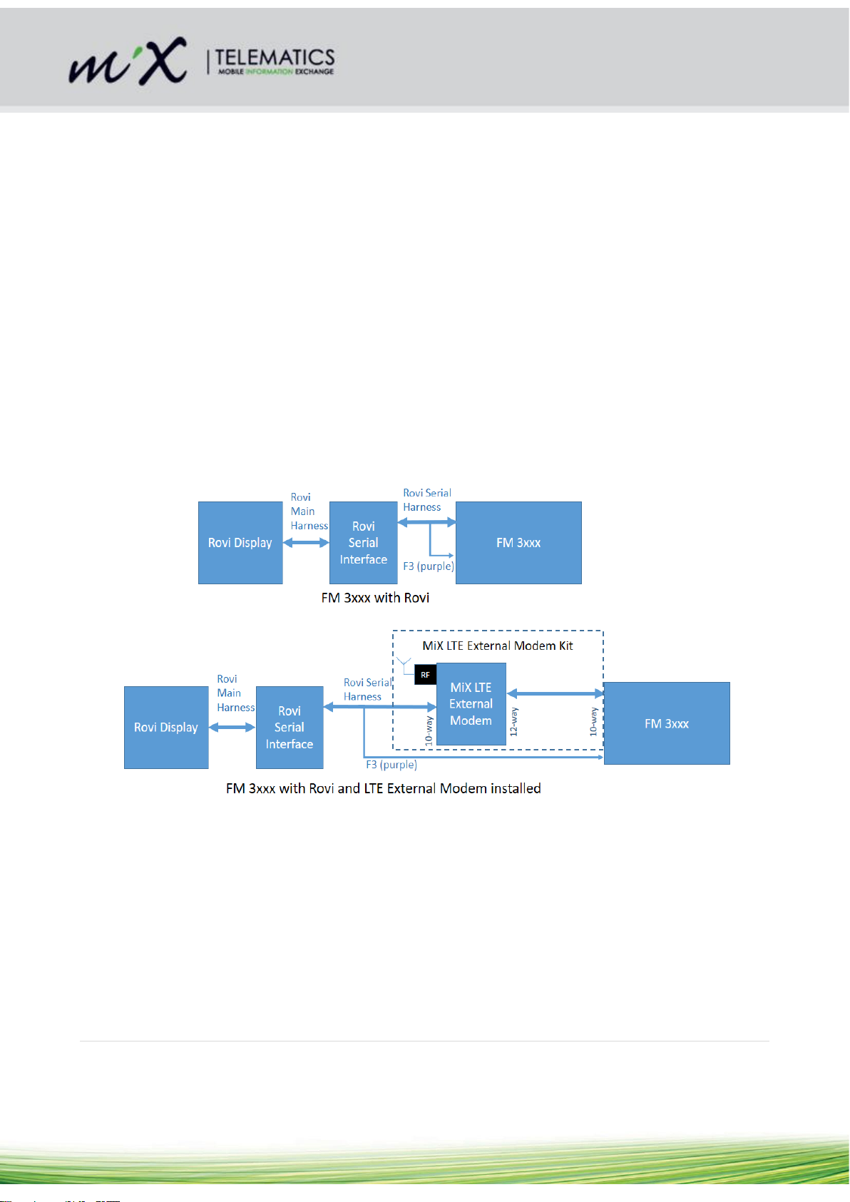
The system should only be installed by a suitably qualified vehicle technician with a basic knowledge of the
operation of telematics equipment and the Rovi Display Unit.
6 Regulatory Compliance
This device complies with Part 15 of the FCC Rules. Operation is subject to the following two conditions: (1)
this device may not cause harmful interference, and (2) this device must accept any interference received,
including interference that may cause undesired operation.
No changes / modifications shall be made to the equipment without the manufacturer’s permission as this
may void the user’s authority to operate the equipment.
This equipment complies with FCC radiation exposure limits for an uncontrolled environment. This
equipment shall be installed and operated with a minimum distance of 20 cm (7.9 in) between users and/or
bystanders and the device.
7 Pre Install Requirements
Before scheduling the install on any asset the steps below should be completed.
7.1 Firmware upgrade
Prior to scheduling any visit to the vehicle the FM firmware on the OBC needs to be updated to
E18.09.06.18 –BAS 1.71C or higher. This needs to be done as an over the air upload. It is important to
have confirmed the OBC is running this firmware before fitting the external modem hardware.
Note: Once this firmware is loaded onto an operational OBC the firmware continues to use the internal
modem until it detects an external modem connected. So the firmware can be upgraded at any time before
the install of the LTE modem takes place with no impact on normal operation.
7.2 Config update
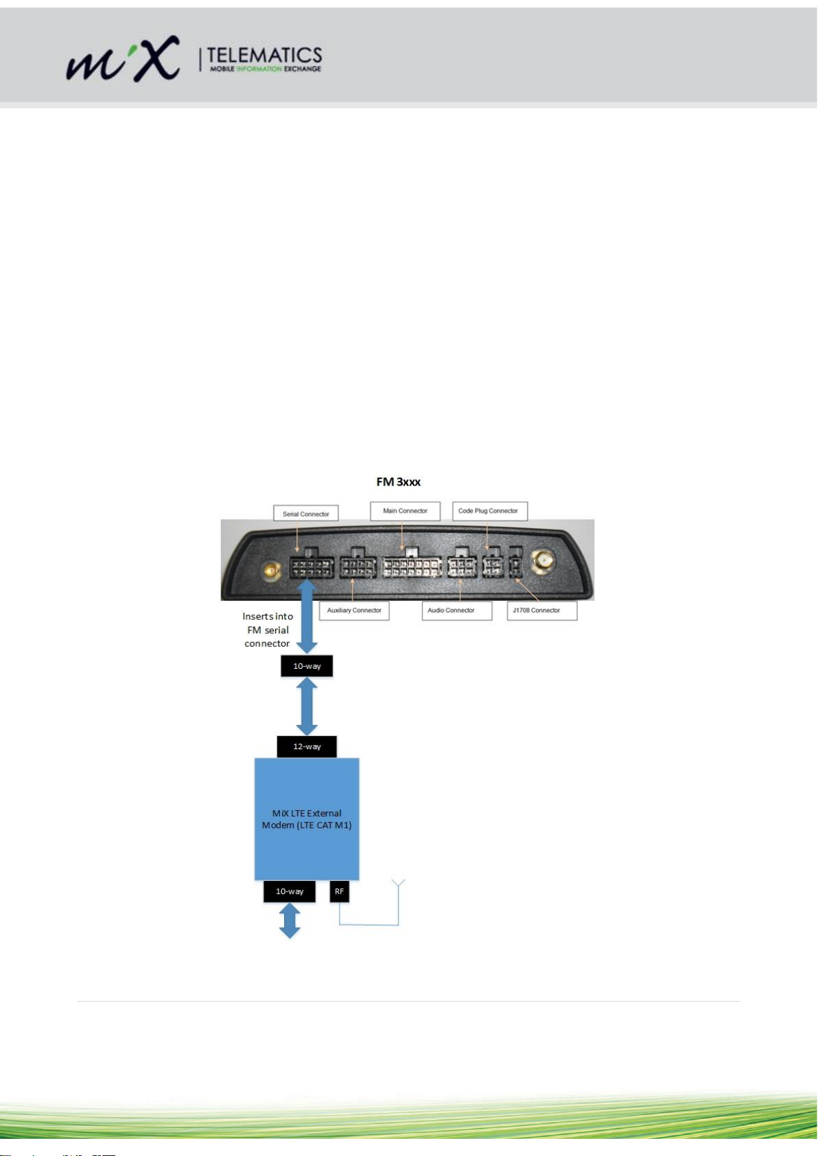
The assets config must be updated to reflect that an external modem has or will be attached to serial line
S3.
Before that can be done the device needs to be made available in the peripheral library.

V1.2 5 | P a g e
Then edit the Mobile device template, locate the S3 line and set it for the LTE Modem.
Note: As this is only suitable for installs that currently have S3 free, this change can be done to the config
any time before the install of the LTE modem takes place with no impact on normal operation.
7.3 Confirm existing SIM details
If the 2G/3G SIM details for the asset are not already recorded it is important to capture these details prior to
the install. This will ensure that the contract on the original SIM can be terminated once the transition to the
LTE modem is successful
Note: The FM 3xxx will report SIM information like the IMSI number which is typically used to link the asset
to a contract with the cellular provider. Once the new LTE modem is installed and operational the details of
the SIM in the LTE modem are reported and the details of the original SIM will no longer be sent by the
OBC.
7.4 Ensure modem has an Activated LTE SIM
The LTE External modem requires its own LTE capable SIM. In some cases a deactivated SIM will already
be inserted in the modem at time of manufacturer e.g. An AT&T SIM is fitted to all stock for MiX NA. The
details of the SIM are included on the modem’s label as well as provided in a digital list with every purchase
order. If the modem is supplied without a SIM, indicated by blank ICCID details on the label, then the SIM

V1.2 6 | P a g e
cover on the modem housing needs to be removed and the SIM inserted in the orientation indicated on the
cover. Activation of the SIM on the cellular provider’s portal must also be done before attempting an install.
The SIM must also be configured not to require any PIN code or the modem will be unable to use it to
connect to the network.
Note: If the install is attempted with a modem not containing an operational, unpinned LTE SIM the OBC will
fail to transition from internal to external modem. The OBC will simply continue to use its internal SIM. This
is a failsafe built in to ensure that communication with the asset is not lost. If there is any doubt in the SIM
activation process then the Installation and Testing steps shown below can be performed by plugging the
modem into a test FM 3xxx device and confirming operation before the Modem kit is supplied for the install.
8 Installing hardware
One MiX LTE CAT M1 Modem kit needs to be available for each asset that is to be upgraded to LTE. The
solution is designed so that the LTE modem and its harness fit in-line with an existing serial harness that
may already be plugged into the FM’s serial connector. See below. This means that this install is a simple
‘plug and play’ without the need for any cutting or splicing into the existing install wiring.
Note: As the S3 line is taken by the LTE modem this line is no longer available and not even passed
through to the serial connector. S1 is however untouched and passed directly through the modem device so
that the original serial peripheral can be reattached.
Figure 2 Overview of System before and after the external modem install

V1.2 7 | P a g e
8.1 Hardware and Kit Part Numbers
Part Number
Name
Picture
Description
P0014MT
LTE Cat M1
External Modem
Kit
LTE Cat M1 External Modem
kit for installation on FM 3xxx
440FT0077
LTE Cat M1
External Modem
LTE Category M1 External
Modem
A0011MT
Serial Harness
SR4
FM LTE Ext. Serial Harness
SR4
A0016MT
External LTE
Antenna PA3
LTE Cat M1 Antenna for
External Modem
8.2 Mounting Considerations
8.2.1 LTE Modem
Select a location close to where the FM 3xxx is installed to mount the LTE modem hardware. Secure the
hardware to the vehicle using at least one zip/cable tie.
8.2.2 LTE External Antenna
Mount the external antenna on a non-metal surface to ensure optimal performance. Use the double sided tape
provided or zip/cable ties to firmly secure the antenna.
Caution:
a) Do not mount the LTE modem on top of the FM 3xxx unit
b) Do not mount the External LTE Antenna on top of the FM GSM Antenna

V1.2 8 | P a g e
9 Installation procedure
Step
Part Number
Picture
Description
1.
A0011MT
And
440FT0077
a. The 12-pin connector of the
“FM LTE Ext. Serial Harness
SR4” should already be
connected to the 12-pin
socket on the LTE Modem. If
not connect these two item
together.
b.
c. Note: it is also possible to
plug the other end of the
harness, the 10-pin
connector, into the modem.
This is incorrect and will not
allow the install to proceed.
2.
A0011MT
If there is anything
connected to the 10-pin
serial connector on the FM
3xxx, disconnect it and
connect it to the 10-pin side
of the LTE modem.
Then
Connect the 10-pin side of
the “FM LTE External Serial
Harness SR4” to the 10 pin
socket (serial port) on the
FM.
3.
A0016M
Connect the External LTE
blade antenna to the socket
on the LTE modem
Note: It has the same
connector as the GPS
antenna on the FM 3xxx.
Leave the GPS antenna

V1.2 9 | P a g e
connected to the FM. The
antenna that comes with the
kit must plug into the external
modem
10 Testing procedure
Testing of the install will require the installer to have access to a Power down plug and a
Communication/GSM Diagnostics plug for the FM 3xxx. These are the same tools used for standard FM
diagnostics and they can be programmed using the Dealer Utility application. See Appendix A
Note: The FM needs the internal SIM and modem to be operational during this process. Make sure it is still
operational and remains installed during the test.
Step
Action
Result
1.
The detection of an externally
connected LTE modem will occur
automatically over time. To force the
process to kick-off immediately after
the modem is connected, insert a
Power down Plug into the code plug
socket of the FM 3xxx to force the
unit to restart and check for a
modem.
d. The FM 3xxx device will reboot. As it starts up it
will determine if an operational external modem is
attached on S3.
2.
Insert the standard
Communication/GSM Diagnostics
Plug into the code plug socket of the
FM.
The LED on the code plug socket will stay on while
the plug is inserted and the unit is in LTE mode.
3.
Confirmation of LTE mode being
actively used by the FM 3xxx is
required.
Confirm that LTE communications is
active.
LTE Communication active - The buzzer will give 5
short widely spaced beeps when LTE mode is
detected.
( . . . . . )
OR
3G/GPRS communication from internal modem –
The buzzer will give 3 shortly widely spaced beeps
when communicating using its internal modem.
(. . . )
4.
Allow time for the device to transition
from internal to external modem.
It may take a few minutes for LTE
communication to be established
The communication beeps will occur when the plug
is first inserted or whenever communications
changes from internal modem to external modem.

V1.2 10 | P a g e
and the LTE beep pattern to be
heard
5.
Confirm the SIM is able to facilitate
an active connection to the network
When a link becomes active the buzzer will give 2
quick short beeps.
( . . )
6.
Confirm normal operation of the LTE
modem
Modem is idle with no incoming data
When the OBC successfully queries the modem for
data, but there is no incoming data, the buzzer will
give 1 medium beeps.
( - )
This usually occurs around once a second (but
could be longer for a very slow config).
7.
Confirm normal operation of the LTE
modem
Modem is receiving data
When data is received, the buzzer will give 2
medium beeps.
( -- )
This usually occurs once a second (but could be
longer for a very slow config).
8.
Confirm normal operation of the LTE
modem
Modem is sending data
When an active message is sent, the unit will give
5 quick short beeps.
( . . . . . )
9.
Confirm the modem is not
continuously in an error state where
it is unable to send or receive data
Occasionally the modem will report an error. This
will be indicated by a long beep.
( ___ )
If this occurs continuously the modem is not
working as it should and the install cannot be
completed.
11 Post install administration
Once the install is confirmed the FM 3xxx OBC will use the external LTE modem for all its communication
going forward. The firmware does not implement any fallback to 2G/3G by switching back to the internal
modem if the OBC it is out of LTE coverage. There is therefore no point in keeping the original internal SIM
active. The original SIM can be deactivated using the details captured for the asset prior to installing the LTE
External modem.

V1.2 11 | P a g e
12 Appendix A – Diagnostics Plugs Required
12.1Creating a Power down plug
Using the Dealer Utility and a standard blue plug, open the format menu and select ‘Power down plug’. Once
formatted correctly this plug should be marked as a power down plug. It will be used after the LTE External
modem has been attached to force the FM to check for the additional modem.
12.2Creating a Communication diagnostics plug
Using the Dealer Utility and a standard blue plug, open the format menu and select Diagnostics ->
DECT/GSM/SMS/GPRS. Once formatted it should be marked as a Communication Diagnostics plug, also
often referred to as a GSM plug. It will be used when confirming that the external modem is communicating
correctly.
Table of contents
Other Mixtelematics Automobile Accessories manuals
Popular Automobile Accessories manuals by other brands

Lippert Components
Lippert Components Jack-It manual

Havis-Shields
Havis-Shields Kwik-Kit KK-100-03 Specification sheet

AMP Research
AMP Research PowerStep 76332-01A installation guide

Big Mikes Performance Parts
Big Mikes Performance Parts STO N SHO SNS 82 Installation procedures

Holley
Holley 0-80508S INSTALLATION, TUNING, AND ADJUSTMENT MANUAL

Enthuze
Enthuze ENT5089 Assembly and Use