Mixtelematics FM36**i series User manual

FM36xxi, FM37xxi,
FM38xxi
Installation Manual

2 | P a g e
Table of Contents
1Introduction...............................................................................................................................................3
1.1 Analogue/Digital Inputs .....................................................................................................................3
1.2 Frequency Inputs...............................................................................................................................3
2System Requirements ..............................................................................................................................3
3Safety........................................................................................................................................................4
3.1 Before installation:.............................................................................................................................4
4Installation.................................................................................................................................................8
4.1 Installation Requirements..................................................................................................................8
4.2 Summary of Installation Steps...........................................................................................................8
4.3 Overview............................................................................................................................................9
4.4 Tools and inspection .........................................................................................................................9
4.5 Connection ......................................................................................................................................10
4.6 Inserting of SIM card .......................................................................................................................13
4.7 Beep and flash codes......................................................................................................................13
5Harness Installation................................................................................................................................17
5.1 Description of connectors................................................................................................................17
5.2 Connector the Main harness wires according to the following table:..............................................18
5.3 Connect the Auxiliary harness wires according to the following table: ...........................................19
5.4 Connect the Code plug harness wires according to the following table:.........................................19
5.5 Connect the Serial harness wires according to the following table:................................................20
6Starter Interruption..................................................................................................................................21
6.1 Code Plug Socket Installation .........................................................................................................22
6.2 Positioning the FM 3617i/FM 3717i/FM 3817i Unit .........................................................................22
6.3 Signal Inputs....................................................................................................................................23
6.4 Power Outputs.................................................................................................................................24
6.5 Serial Communication .....................................................................................................................25
6.6 Loading Device Drivers ...................................................................................................................25
6.7 Configuring Vehicle Properties........................................................................................................26
6.8 Setting the Real Time Clock............................................................................................................26
6.9 Speed and RPM Calibration............................................................................................................27
6.10 Testing Installation.......................................................................................................................29
6.11 Voice / Hands-free connection....................................................................................................29
6.12 GPS antenna connection ............................................................................................................29
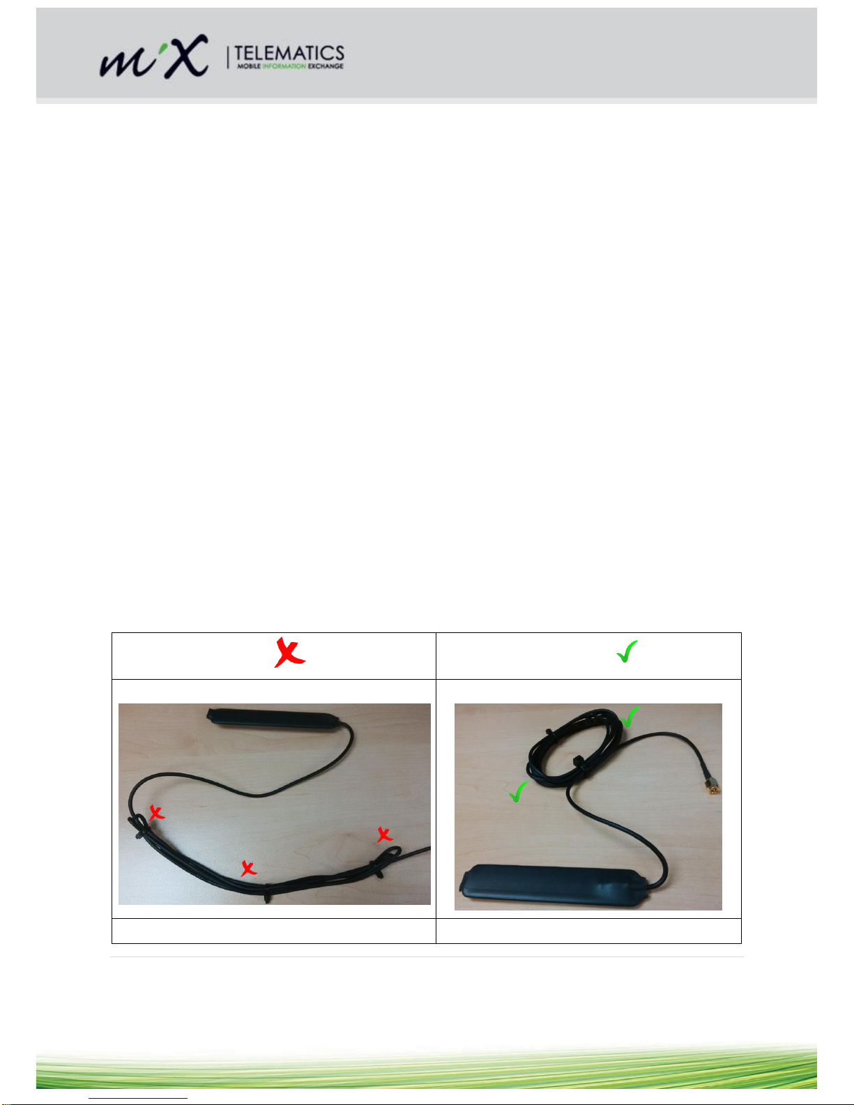
6.13 GSM Antenna connection ...........................................................................................................29
7Troubleshooting......................................................................................................................................30
8Maintenance ...........................................................................................................................................30
9FM 3617i/FM 3717i/FM 3817i Specifications .........................................................................................31
9.1 Technical description.......................................................................................................................31
9.2 Technical specifications ..................................................................................................................32
9.3 Auxiliary inputs/outputs ...................................................................................................................36
9.4 Look up table for installers to determine Speed and RPM FM Dealer Sensitivity Settings ............37
10 Statutory and Regulatory Compliance ............................................................................................39

3 | P a g e
1 Introduction
This document is applicable to the FM 36xxi, FM 37xxi and FM 38xxi series
of on-board computers. These products are collectively referred to as FM
3617i/FM 3717i/FM 3817i.
The FM unit is a comprehensive fleet management solution, comprising
of an in-vehicle on-board computer as well as an easy to use web
interface, MiX Fleet Manager, which enables access to fleet management
information anytime, anywhere.
The FM3717i/38171 range supports 3G and 3.5G HSPA+, 3-Axis
Accelerometer (up to 16 G) and GLONASS.
The FM3617i range supports 3-Axis Accelerometer (up to 16 G) and
GLONASS.
Please note: This document will use the word “vehicle”, referring to vehicles and all other types of electrical
equipment where these units may be installed.
1.1 Analogue/Digital Inputs
The FM 3617i/FM 3717i/FM 3817i is equipped with eight analogue/digital inputs (I1-I8), which can be used to
monitor either digital or analogue signals. The eighth Analogue/Digital input (I8) is shared with the fourth
frequency input (F4). Input signal voltage range and resolution is selectable from the MiX Fleet Manager
software. For digital type input signals, switching thresholds can be defined in the software, which, when
crossed, trigger an event that records the specified data. Other actions (including the switching of relays and
warnings) can also be defined. Please refer to the “Specifications” section, of this document, for more details.
1.2 Frequency Inputs
The FM 3617i/FM 3717i/FM 3817i has three frequency inputs, which can be used to record frequency type
signals. The fourth frequency input (F4) is shared with the eighth Analogue/Digital input (I8). Provision is made
for a wide range of signal types on F1 and F2. F4 will only read TTL signals, or signals that span at least 0V
to 5V, e.g. -5V to +24V. F3 is no longer a frequency input, but it is connected to the internal GPS and acts as
a GPS output (9600 baud).
2 System Requirements
The FM 3617i/FM 3717i/FM 3817i is designed for use in vehicles. Special vehicles and working machines with
a 24 to 110 volt DC battery system will require a voltage converter to facilitate the required 12V to 24V power
supply input. MiX Fleet Manager is required to complete the installation process.

4 | P a g e
3 Safety
3.1 Before installation:
3.1.1 Installer Requirements
Installation should only be undertaken by a vehicle technician with comprehensive occupation specific
knowledge and who has complete command of the actions required by the occupation.
Installation by an unqualified technician may adversely affect the operating reliability of the vehicle
and could endanger other road users.
A basic knowledge of vehicle electrical and mechanical systems is required to successfully install the
Fleet Manager system.
The system should only be installed by a suitably qualified vehicle technician with a basic knowledge
of the operation of computers.
Installation technicians should attend a training course to acquire the skills needed for installation,
configuration and operation of the Fleet Manager system.
Installers should consult the vehicle manufacturer’s documentation for the specific vehicle make and
model prior to undertaking an installation.
Installers should pay particular attention to the location of fuel systems, hydraulic systems,
compressed air systems and other electrical and mechanical systems, which may have a bearing on
the installation.
Installers should pay attention to any changes to the vehicle’s systems or settings, which should be
noted prior to the installation.
Installers should not smoke or make use of naked flames, which could cause a fire in or near the
vehicle.
3.1.2 Tools
Standard technical equipment and appropriate tools for use with vehicles are required to install the
FM 3617i/FM 3717i/FM 3817i.
Vehicle specific tools may be required for the removal of consoles and covers.
3.1.3 Secure the workplace
Remove the ignition key from the vehicle’s ignition lock.
Ensure that the vehicle’s engine cannot be unintentionally started during the installation.
Short-circuiting the vehicle’s electrical system may result in fire, explosion of the battery and/or
damage to other electrical systems.
Care should be taken to avoid electrical shock from high voltage batteries, as this may lead to death
or injury.
The negative terminal of the vehicle’s battery should be disconnected before commencing installation.
If the vehicle has additional batteries, it may be necessary to disconnect the negative terminals of
these batteries too.
3.1.4 ESD Precautions
Prior to touching the PCB, inserting a new SIM, replacing the battery or changing the jumper’s settings, always
take ESD precautions:
Remove the main harness connector
Touch the golden portion of the RF connector to get to the same potential as the unit

5 | P a g e
3.1.5 During installation
Should it be necessary to remove seats, covers or other components, care should be taken to avoid
accidental damage and/or disconnection of cables.
All components should be checked for damage prior to being installed into the vehicle.
For small installation openings, a drill should be used.
For larger openings, a conical milling cutter, compass saw or file should be used.
All rough edges should be trimmed.
Careful attention must be paid to the manufacturers’ safety regulations for all tools used.
Oils and fuels must be collected in appropriate containers and disposed of in accordance with the law.
3.1.6 Positioning of product components
Installers should ensure that the components of the product do not influence or hamper the functioning
of the vehicle’s systems.
Care should be taken to ensure that the product’s components do not get damaged during installation.
Ensure that sufficient space is available for all components of the product, prior to commencing the
installation.
Ensure that the unit and harness are secured to prevent the harness vibrating at a different tempo to
the unit at the harness connectors.
Please note that the voltage of the external relay is rated to the vehicle voltage specification. Do not
run a 12V relay at 24V. The Relay Specifications are:
Coil current rating: < 200 mA
Coil Voltage Rating: Must match the vehicle battery supply
Please pay attention to the routing course of cables and wiring.
Do not install the product in or near the location of mechanical or electrical airbags.
Do not drill into supporting or stabilizing braces or beams.
Note that the product is rated IP 54, on condition that the connectors are facing downwards when installed.
Thus, if there is a possibility of water ingress, care should be taken to mount the product with the connector
facing downwards.
3.1.7 Installation of Wiring
The FM 3617i/FM 3717i/FM 3817i is compatible with all FM300 harnesses.
Note the product’s wire gauge cross-sectional area. If the wire gauge cross-section is reduced, current density
increases which may cause the wiring to overheat.
Cables should be routed in existing channels and should not be routed parallel to ignition cables or
other cables subject to high current (including cigarette lighter socket wires).
Cables should be fixed with cable-ties or adhesive tape.
Do not route cables over moving parts.
Do not fix cables on the steering column.
Ensure that the cables are not exposed to pulling, pressure or shearing deformation.
If the cables are routed through drilled holes, rubber grommets or similar protection should be used.
Suitable cable-strippers should be used to strip insulating material from cables and cable-strippers
should be adjusted to avoid damaging or separating the wire strands.

6 | P a g e
Cables should only be connected using a soldering iron or suitable crimping lugs.
A proper crimping tool should be used on all crimping lugs.
Careful attention must be paid to the manufacturers’ safety regulations for all tools used.
Insulate all exposed wires to prevent short-circuits. Use good quality adhesive tape or heat shrink
(provided).
Connections to vehicle power supply must be installed with a fuse.
Be aware that short-circuiting may be caused by faulty connections and crushed or damaged cables.
Short-circuiting the vehicle’s electrical system may result in fire, explosion of the battery and/or
damage to other electrical systems. To prevent this, all connections carrying current must be soldered
and insulated correctly. Other connections such as the speed signal, RPM signal, brake light or clutch
switch can be made with crimping lugs.
Incorrect connections can lead to short circuits. Connections should only be made in accordance with
the vehicle’s wiring diagram.
Current and voltage should be measured with a multi-meter or diode test lamp.
The use of inadequate test equipment may result in damage to control devices or other electrical
systems.
Route the harness in such a way to prevent water condensation formed on the cable to run into the
unit. This can be achieved by having the harness at a lower point just before it connects to the unit.
Shortening of antenna wires:
It would be better to circle/coil excess wires. Avoid sharp bends at the zigzags. Take
care not to tie coax wires too tight. The coax should not be squeezed or pinched.
Using the broadest possible cable tie.
The best place to circle/coil the wires is about 300 mm in line from the antenna.
If the GSM and GPS antennas are both coiled, they should be spaced apart.
Do not mount the GSM antenna against a metal surface. This affects GSM reception
and transmission.
Avoid
Recommended
Avoid sharp corners and bends:
Use rounded bends:
Avoid coupling between 2 different pieces of wire:
Separate coiled wires where possible:

7 | P a g e
3.1.8 After Installation
Check all relevant vehicle functions.
Explain the functions of the FM 3617i/FM 3717i/3817i system to the customer and give the customer the
User Manual.
If an OBC with battery backup was installed, the battery should be inspected annually.
3.1.9 During Operation
The unit switches on only with IGN.
The product must be operated in accordance with operating instructions.
Failure to use the product as directed might result in personal injury, material damage and/or damage to
the environment.

8 | P a g e
4 Installation
4.1 Installation Requirements
Please note the requirements specified in the “Safety” section of this document.
4.2 Summary of Installation Steps
Note: Steps 9, 10, 12, 14, 15 & 16 can be performed in one operation using the FM Dealer Utility.
Step
Action
Software Tools
1)
Create new vehicle and define properties,
MiX Fleet Manager
2)
Install harness
None
3)
Install code plug socket
None
4)
Install GSM antenna
None
5)
Install GPS antenna
None
6)
Insert the SIM card (refer to ESD precautions in section 3.1.4).
The SIM card orientation is illustrated in section 4.6.
None
7)
Connect power and signal inputs
None
8)
Put the vehicle Ignition ON for at least 30 sec in order to
initialize the unit. Switch the OFF again.
None
9)
Format 256k Green Plug to a device driver plug
FM Dealer Utility / MiX Fleet
Manager
10)
Load device drivers onto the 256k Green Plug (only necessary
if newer drivers are available)
FM Dealer Utility / MiX Fleet
Manager
11)
Insert the Vehicle Plug into the code plug socket of the unit.
Confirm upload of data by a double beep from the unit.
[Note: Prior to inserting the plug, make sure the unit is still ON.
Thus, if the Code Plug LED is not flashing, then switch the
ignition ON for a few seconds, before switching it OFF again.]
None
12)
The vehicle configuration must be generated from MiX Fleet
Manager. Then load the configuration of the vehicle from the
database onto the Vehicle Plug
FM Dealer Utility / MiX Fleet
Manager
13)
Initialise the installed unit with its Vehicle configuration by
inserting the Vehicle plug into the code plug socket
None
14)
Initialise Driver ID plug (only necessary if driver identification is
selected)
FM Dealer Utility / MiX Fleet
Manager
15)
Set FM 3617i/FM 3717i/FM 3817i date and time (for local time)
FM Dealer Utility / MiX Fleet
Manager
16)
Calibrate Speed and RPM inputs
FM Dealer Utility
17)
Update unit odometer
MiX Fleet Manager / FM Dealer
Utility
18)
Test GSM using GSM diagnostic plug
MiX Fleet Manager / FM Dealer
Utility

9 | P a g e
19)
Test GPS using GPS diagnostic plug
MiX Fleet Manager / FM Dealer
Utility
20)
QC: Test installation/Review data
MiX Fleet Manager
4.3 Overview
Installation of FM 3617i/FM 3717i/FM 3817i should only be carried out by trained installers.
Improper connection of the FM 3617i/FM 3717i/FM 3817i to the vehicle’s CAN or J1708 bus may
cause interference with the vehicle’s normal operation.
The FM 3617i/FM 3717i/FM 3817i is already loaded with compatible device drivers.
The unit still needs to be configured for the vehicle in which it will be installed, and the vehicle ID
and odometer still need to be configured. Specifically the FM 3617i/FM 3717i/FM 3817i may not
record any CAN or J1708 data until it is configured.
It is important to select the correct mounting location for the FM 3617i/FM 3717i/FM 3817i. Do not
mount close to air ducts that can channel cold or hot air directly onto the unit.
Do not twist the FM 3617i/FM 3717i/FM 3817i unit if mounted on an uneven surface.
The GSM antenna is to be mounted more than 20cm away from the human body under normal
operating conditions.
After installation, verify that no interference is caused to the vehicle’s electrical system. Check dashboard
warning lights and error messages. Should any error conditions exist, remove the FM installation and contact
MiX Telematics for assistance.
4.4 Tools and inspection
Supporting tools
Multi-meter
Oscilloscope
Laptop with CAN to USB interface (for example Vector CANcaseXL)
Identify possible CAN busses by looking for twisted pair wires in the vehicle.
With the vehicle’s ignition turned on, measure the voltages relative to ground on each of the wires using a
multi-meter.
For CAN, the voltage readings of the two wires should be very similar (usually 2.5V), with CAN-H likely to
read only slightly higher than CAN-L.
Using an oscilloscope, the actual data signal can be probed.
With a properly configured 3rd party CAN tool, like the Vector CANcaseXL, the actual data can be recorded.
CAN Baud rates of 250kb/s (SAE J1939) and 500kb/s are the most common.

10 | P a g e
4.5 Connection
The CAN wires are designated by a yellow and a green wire, connected to pins 7 and 14 on the Main Harness.
If they are not already twisted, they should be twisted together.
Colour coding of the wires are shown in the tables below:
Table 1: FM300 Main Harness CAN colour coding
Wire Colour
Function
Green
CAN-Low
Yellow
CAN-Hi
Table 2: FM 3316 J1708 harness wire colour coding
Wire Colour
Function
Yellow
J1708 B
Blue
J1708 A
4.5.1 Wire lengths
The CAN wires between the FM 3617i/FM 3717i/FM 3817i and the vehicle’s bus should be no longer than 300
mm. Excessive wire length may cause interference with the vehicle’s normal operation.
4.5.2 CAN jumper settings
Warning: It is very important to ensure that these jumper settings are correct at installation time. If these
jumpers are set incorrectly it is possible that when a new configuration or script is downloaded to the FM
3617i/FM 3717i/FM 3817i, it could bring down the CAN bus of the vehicle and interfere with the operation of
the vehicle. Conduct ESD precautions as described in section 3.1.4
Refer to
Description
Error!
eference
source not
found.
FM 36xxi / FM 37xxi/FM 3817i Circuit board showing jumper positions for “listen only” CAN
mode without 120 Ωtermination
Figure 2
FM 36xxi / FM 37xxi/FM 3817i Circuit board showing jumper positions for “listen only” CAN
mode with 120 Ωtermination
Figure 3
FM 36xxi / FM 37xxi/FM 3817i Circuit board showing jumper positions for “read/write” CAN
mode with 120 Ωtermination
Figure 4
FM 36xxi / FM 37xxi/FM 3817i Circuit board showing jumper positions for “read/write” CAN
mode without 120 Ωtermination

11 | P a g e
For “listen only” CAN and no
120 Ωtermination; jumpers J2
and J12 must be as per
picture in Figure 1
Figure 1 FM 36xxi / FM 37xxi / FM 3xxi Circuit board showing jumper positions for “listen
only” CAN mode without 120 Ω termination
For “listen only” CAN and 120
Ωtermination; jumpers J2 and
J12 must be as per picture in
Figure 2.
Figure 2 FM 36xxi / FM 37xxi / FM 3xxi Circuit board showing jumper positions for “listen
only” CAN mode with 120 Ω termination
J1939 CAN (Listen Only)
Without 120 Ohm termination
Use this setting when the FMS gateway
does not require an “acknowledgement”
message on the hardware layer.
J1939 CAN (Listen Only)
With 120 Ohm termination
Non-standard setting

12 | P a g e
To allow “read/write” CAN and
120 Ωtermination; jumpers J2
and J12 must be connected
as per picture in Figure 3.
This is the factory default
setting for all new units.
Figure 3 FM 36xxi / FM 37xxi / FM 38xxi Circuit board showing jumper positions for
“read/write” CAN mode with 120 Ω termination
For “read/write” CAN without
120 Ωtermination; jumpers J2
and J12 must be as per
picture in Figure 4.
Figure 4 FM 36xxi / FM 37xxi / FM 38xxi Circuit board showing jumper positions for
“read/write” CAN mode without 120 Ω termination
J1939 or OBDII CAN (Read /
Write)
With 120 Ohm termination
Use this setting for OBDII or
when the FMS gateway
expects an
“Acknowledgement” message
on the hardware layer.

13 | P a g e
4.5.3 General Rules for CAN Jumpers
If connectivity is to the vehicle CAN FMS “firewall” then both jumpers are normally in as shown in
Figure 3. Some FMS gateways requires an “acknowledgement” message on the hardware layer in
order to send any messages and therefore the FM must be in the “read/write” mode. Check that the
resistance is 60 Ohms after connecting the FM unit and then remove the “Termination Jumper” if
necessary as shown in Figure 4. Sometimes a terminating resistor or other telematics equipment may
already have a terminating 120 Ohm resistor fitted; in this case the terminating resistor can be
removed and the “read/write” resistor can be left in as shown in Figure 4
.
If there is no FMS “firewall” fitted, then connectivity will be to the vehicle CAN “hot side” – only with
customer’s permission –then both jumpers must be removed as shown in Figure 1. Prior to
commencing the installation, check that the vehicle CAN resistance is 60 Ohms, if it is not, e.g. 40
Ohms or 120 Ohms, inform the customer as this should be corrected prior to commencing the
installation. If a reading of 40 Ohms is present, prior to connecting the FM unit, this could indicate that
another telematics system may already be present with a terminating 120 Ohm resistor fitted and this
will distort the CAN resistance reading and may cause CAN errors to be seen.
4.6 Inserting of SIM card
In order to insert the SIM card, the following steps must be followed:
Observe ESD precautions as prescribed in section 3.1.4
Remove the front panel
The SIM card holder is located under the pc board
If required the pc board can be slid out of the housing to access the SIM card holder
Insert the SIM card as indicated below
4.7 Beep and flash codes
4.7.1 Code Plug Socket LED flash codes
Upon the insertion of a CAN Diagnostic Plug the FM 3617i/FM 3717i/FM 3817i will beep and flash the LED on
the code plug socket, in accordance with the table below, to provide diagnostic information:
Condition
Beep and Flash Code
Durations
CAN Functionality Detected by OBC
No Beeps
1second on, 1second off
CAN Communications Detected by OBC
1 double beep per second
1second on 1second off

14 | P a g e
FM device is not CAN capable
1 error beep per second
1second on 1second off
A CAN Diagnostic Plug may be created from a standard 128 byte code plug using the FM Dealer Utility,
version 8.3.1.0 or later.
4.7.2 GPS LED flash codes
(Viewed from the front unit: LED to the left, below the GPS RF connector for external antenna)
GPS has acquired lock. The FM will
subsequently be able to report accurate GPS
points.
No Beeps
LED is ON for a short time every
second
Upon the insertion of a GPS Diagnostic Plug the FM 3617i/FM 3717i/FM 3817i will beep and flash the LED on
the code plug socket, in accordance with the table below, to provide diagnostic information:
Data received from GPS with errors
1 half second beep occurs each
time an error is detected
The lamp flashes when data is
received from the GPS
GPS data received - position not
determined
One short beep occurs when
GPS data is received with
position undetermined
The lamp flashes when data is
received from the GPS
GPS data received - position determined
Two short beeps occur when
GPS data is received with the
position determined
The lamp flashes when data is
received from the GPS

15 | P a g e
4.7.3 GSM LED flash codes
Upon the insertion of a GSM/GPRS Diagnostic Plug the FM 3617i/FM 3717i/FM 3817i will beep and flash the
LED on the code plug socket, in accordance with the table below, to provide diagnostic information:
Pin Error
Two long beeps occur if the
supplied PIN code was rejected.
The lamp flashes when valid
responses are received from the
GSM modem
Modem registered on GSM network
Two short beeps indicate that
the modem is logged onto a
GSM network and is GPRS
capable.
The lamp flashes when valid
responses are received from the
GSM modem.
Connection Established
Three short beeps indicate that
the modem has changed from
GSM modem to GPRS mode.
This also means that a GPRS
connection to the GSM network
is established
The lamp flashes with results
from the modem

16 | P a g e
4.7.3.1 FM 36xxi 2G Modem
(Viewed from the front unit: LED to the right, below the GSM RF connector for external antenna)
GSM does not have any reception: No SIM
card inserted or no PIN entered, or network
search in progress or ongoing user
authentication or network login in progress
No beeps
600 ms ON / 600 ms OFF
Idle mode: The GSM is registered to the GSM
network (monitoring control channels and user
interactions). No call in progress
No beeps
75 ms ON / 3 s OFF
GPRS: Unit is registered to network and
capable of connecting via GPRS.
No beeps
75 ms ON / OFF/ 75 ms ON/ 3 s
OFF
Packet switched data in progress
No beeps
500 ms ON / 50 ms OFF
4.7.3.2 FM 37xxi/FM 38xxi 3G Modem
(Viewed from the front unit: LED to the right, below the GSM RF connector for external antenna)
Limited Network Service (e.g. because no
SIM/USIM, no PIN or during network search)
No beeps
500 ms ON / 500 ms OFF
GSM CS data call in progress or established
GSM voice call in progress or established
UMTS voice call in progress or established
UMTS CS data call in progress
No beeps
10 ms ON / 990 ms OFF
UE registered to a network. No call, no data
transfer
No beeps
10 ms ON / 3990 ms OFF
GSM PS data transfer
UMTS data transfer
No beeps
10 ms ON / 1990 ms OFF

17 | P a g e
5 Harness Installation
Please read the “Safety” section, of this document, before installing the vehicle harness.
5.1 Description of connectors
PIN numbering configuration on these connectors, when viewed from the front is as follows:
Serial Connector
10
9
8
7
6
5
4
3
2
1
Auxiliary Connector
8
7
6
5
4
3
2
1
Main Harness Connector
14
13
12
11
10
9
8
7
6
5
4
3
2
1
Code Plug Connector
4
3
2
1
Audio Connector
6
5
4
3
2
1
J1708 Connector
1
2
Serial
Connector
Main Connector
Code Plug
Connector
Auxiliary
connector
Audio connector
J1708 connector

18 | P a g e
5.2 Connector the Main harness wires according to the following table:
Pin
Colour
Name
Function
Application Information
8
Red
BATT+
Battery Power
Connect to vehicle battery +12V to +24V.
Must be protected with the provided 5 amp slow blow fuse, or a similar
one already present in the vehicles wiring.
1
Brown
GND
Ground
Connect directly to vehicle ground.
Do not tap into an existing ground wire carrying high current.
13
Black
IGN
Ignition
Connect to vehicle ignition switch.
Must be protected with a 7.5 amp fuse
12
Blue/White
F1
Frequency Input
1
Vehicle speed signal connected here.
Connect TCO to only F1 input.
4
Green
F2
Frequency Input
2
Engine speed signal (RPM) connected here
11
White/Violet
I1
Digital/Analog
Input 1
Maximum signal voltage = 38V.
Do not connect signals from unsuppressed inductive sources such
relay coils (where severe voltage spikes can be generated)
10
White/Red
I2
Digital/Analog
Input 2
Maximum signal voltage = 38V.
Do not connect signals from unsuppressed inductive sources such
relay coils (where severe voltage spikes can be generated)
9
White/Green
I3
Digital/Analog
Input 3
Maximum signal voltage = 38V.
Do not connect signals from unsuppressed inductive sources such
relay coils (where severe voltage spikes can be generated)
2
Red/Blue
Pos DRV
Power to external
devices
Supplies power to a speed sensor
Output voltage typically BAT - 2V
Load current must not exceed 800 mA
Output controlled by FM 3617i/FM 3717i/FM 3817i and selected in
Vehicle Properties of front end user software.
5
Brown/Red
EXT
DRIVE 1
Relay Drive 1
Connect the ground side of an external relay coil here.
Relay operation is controlled by the FM 3617i/FM 3717i/FM 3817i and
is specified in Vehicle Properties of front end user software.
Coil current must not exceed 200mA
6
Brown/Blue
Relay
Starter
interruption
Connect to external relay coil, if starter interruption is required.
External coil current must not exceed 200mA.
NOTE: Do not interrupt starter circuit while current is flowing
(especially at higher voltages than 24V) –the relay contacts may
undergo excessive wear, damage or arcing and fire may result.
3
Yellow/Green
BUZ
Buzzer Power
Connected internally , no additional connection required
7
Green
CAN Bus
CAN-Low
Used to monitor supported CAN scripts
14
Yellow
CAN Bus
CAN-Hi
Used to monitor supported CAN scripts
Relay
87
BLACK 2mm
Diameter
RELAY
RELAY Switch
Relay contact #87 wire
Relay
30
BLACK 2mm
Diameter
RELAY
RELAY Switch
Relay contact #30 wire

19 | P a g e
5.3 Connect the Auxiliary harness wires according to the following
table:
Pin
Colour
Name
Function
Application Information
1
Brown
GND
Ground
Connect directly to vehicle ground.
Do not tap into an existing ground wire carrying high current.
8
Violet
F3
GPS Output
GPS NMEA TTL (0 –5V) output (9600 baud)
7
White/Yellow
I4
Digital/Analog
Input 4
Maximum signal voltage = 38V.
Do not connect signals from unsuppressed inductive sources such relay coils
(where severe voltage spikes can be generated).
6
White/Black
I5
Digital/Analog
Input 5
Maximum signal voltage = 38V.
Do not connect signals from unsuppressed inductive sources such relay coils
(where severe voltage spikes can be generated).
5
White/Blue
I6
Digital/Analog
Input 6
Maximum signal voltage = 38V.
Do not connect signals from unsuppressed inductive sources such relay coils
(where severe voltage spikes can be generated).
4
White/Brown
I7
Digital/Analog
Input 7
Maximum signal voltage = 38V.
Do not connect signals from unsuppressed inductive sources such relay coils
(where severe voltage spikes can be generated).
3
White
I8/F4
Digital/Analog
Input 8
Frequency Input 4
Maximum signal voltage = 38V.
Do not connect signals from unsuppressed inductive sources such relay coils
(where severe voltage spikes can be generated).
2
Red/Blue
Positive
Drive
Power external
devices
A maximum current of 800 mA may be supplied to external devices
5.4 Connect the Code plug harness wires according to the following
table:
Pin
Colour
Name
Function
Application Information
1
Black
GND
Code Plug Ground
Connected directly to code plug socket connector.
No additional connection required.
4
Green
CPDATA
Code Plug Data
Connected directly to code plug socket connector.
No additional connection required.
3
Red
CPPOWER
Code Plug Power
Connected directly to code plug socket connector.
No additional connection required.
2
White
LEDOUT
Code Plug Socket LED
Connected directly to code plug socket connector.
No additional connection required.

20 | P a g e
5.5 Connect the Serial harness wires according to the following table:
Pin
Colour
Name
Function
Application Information
2
DB9 cable
CTS2-IN
Handshaking
S3
3
DB9 cable
RX2-IN
Data received
S3
4
RJ45 cable
RX-IN
Data received
S1
5
RJ45 cable
RTS-OUT
Handshaking
S1
1
Red/Blue
POS DRV
Power
BAT - 2V @ 800mA
7
DB9 cable
RTS2-OUT
Handshaking
S3
8
DB9 cable
TX2-OUT
Data transmitted
S3
9
RJ45 cable
CTS-IN
Handshaking
S1
10
RJ45 cable
TX-OUT
Data transmitted
S1
6
Brown
GND
0V (Ground Reference)
0V @1A
This manual suits for next models
5
Table of contents
Other Mixtelematics Automobile Accessories manuals