Mixtelematics Talk User manual

MiX Talk
Installation Guide

2 | P a g e
Table of Contents
1Introduction...............................................................................................................................................3
1.1 Glossary Terms.................................................................................................................................4
1.2 Hardware Features............................................................................................................................4
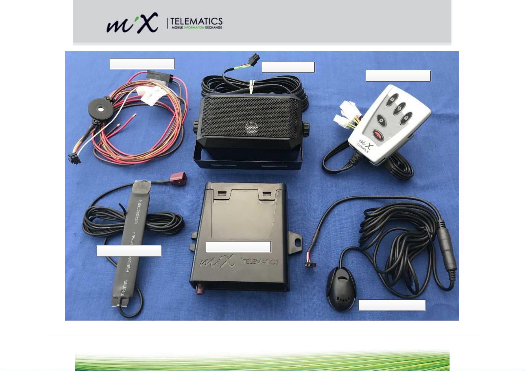
1.3 Product Parts and Spare Parts..........................................................................................................5
1.4 Power Requirements.........................................................................................................................7
2Safety Precautions....................................................................................................................................7
3Prior to Installation....................................................................................................................................7
3.1 Preparing the SIM card .....................................................................................................................7
3.2 Inserting of SIM card .........................................................................................................................7
3.3 Configuration of unit ..........................................................................................................................7
3.4 SMS Configuration ............................................................................................................................8
3.5 Configuration Using a PC Based Application....................................................................................8
3.6 Mix Fleet Manager.............................................................................................................................8
4Installation.................................................................................................................................................9
4.1 Installation Steps...............................................................................................................................9
4.2 During installation..............................................................................................................................9
4.3 Positioning of product components...................................................................................................9
4.4 General Wiring Requirements.........................................................................................................10
4.5 Harnesses and connectors..............................................................................................................11
4.6 Wiring and Connections ..................................................................................................................14
5After Installation......................................................................................................................................14
5.1 Initial Start-up ..................................................................................................................................14
5.2 LED flash codes ..............................................................................................................................14
5.3 Testing Installation ..........................................................................................................................14
5.4 Closing Steps ..................................................................................................................................14
6General Operation..................................................................................................................................15
6.1 Keypad Functions............................................................................................................................15
7Troubleshooting......................................................................................................................................16
8Routine Maintenance..............................................................................................................................16
9Product Specifications............................................................................................................................16
9.1 Technical description.......................................................................................................................16
10 Appendix A: Safety.................................................................................................................................17
10.1 Installer Requirements ....................................................................................................................17
10.2 Precautions......................................................................................................................................17
11 Appendix B: Configurable Parameters...................................................................................................18
11.1 Unit Serial Number..........................................................................................................................18
11.2 IMEI Number ...................................................................................................................................18
11.3 MASTER Number............................................................................................................................18
11.4 CONFIG Number.............................................................................................................................18
11.5 Button Number ................................................................................................................................18
11.6 Incoming Call Number.....................................................................................................................19
11.7 SMS Centre Number.......................................................................................................................19
11.8 Low Power Timer.............................................................................................................................19
11.9 Call Length Timer............................................................................................................................19
11.10 Call Continue Timer.....................................................................................................................19
11.11 Incoming Ring Timer ...................................................................................................................19
11.12 Auto Answer Timer......................................................................................................................20
11.13 Set Open Line..............................................................................................................................20
12 Appendix C: Configuration via SMS message. ......................................................................................21
13 Appendix D: Configuration via PC/Laptop Application...........................................................................28
13.1 Setup Unit with Harnesses..............................................................................................................28

3 | P a g e
1 Introduction
The MiX Talk unit together with
its accessories is a dedicated
hands free cellular telephone
system, which is primarily used
in Fleet Management
applications.
The hands free system
provides superior audio quality
when operating in full duplex in
GSM and 3G networks. The
system also provides an
auxiliary output that can be
connected directly to an in-cabin
radio to further enhance the
incoming audio quality as well as
ease of operation.
An external RF antenna mounted
inside the vehicle’s cabin is used to
ensure extended network coverage.
The MiX Talk unit supports fixed dialling and fixed incoming call numbers for easy administrative
management.
The MiX Talk unit can be directly setup and configured via a serial data cable connected to either a
Laptop or PC. The unit can also be configured remotely via SMS. The MiX Talk Unit does not support
any continuous GSM data transmission.
Once installed operators and service technicians will have limited access to its SIM card. Furthermore
each individual unit will have its own encoded SIM pin number for further security against unauthorised
usage.

4 | P a g e
1.1 Glossary Terms
ABBREVIATION
DESCRIPTION
BT
Bluetooth
GPS
Global Positioning System
GSM
Global System for Mobile Communications
GND
Ground (0V)
RX
Receive
TX
Transmit
WiFi
Local Area Wireless Computer Network
1.2 Hardware Features
Hands Free Operation
The MiX Talk system consists of a main control unit together with a
separate keypad, microphone, speaker and external RF antenna. These
items are fixed installed inside the vehicle’s cabin. The system provides
complete hands free operation only. It does not cater for any hand held
microphone and/or speaker.
Separate SIM Card
The unit will have its own SIM card. Operators and service technicians
will have limited access to SIM card, which is housed within the main
control unit. The SIM pin number is encoded for each individual unit to
further increase security against unauthorised usage.
Configurable "Dialling List"
and “Incoming Call List”
The unit provides an operator or service technician with the ability to
configure and change a list of allowed phone numbers. The Dialling List
can take up to 4 numbers. Apart from the numbers in the Dialling List, the
Incoming Call List can take an additional 4 numbers. The Incoming Call
List can also be configured as an Open Line in which case an incoming
call can be from any number.
Auto Answer
The unit can be configured to automatically answer an incoming call after
a predefined number of rings. The number of rings is also configurable.
Direct and/or Remote
Configuration
The MiX Talk unit can be directly setup and configured via a serial (RS-
232) data cable connected either to a Laptop or PC. Direct setup and
configuration can also be done remotely via SMS.
Keypad Display
The human interface to the system is via a keypad display unit. See
figure above. The keypad section has 5 buttons and the display section
consists of 6 LEDs.
Speaker and Microphone
The MiX Talk system comes with a separate speaker and microphone
which are fixed installed inside the vehicle’s cabin.
Volume Control
The volume of the speaker is manually adjustable via a knob on the
speaker unit.

5 | P a g e
Ringer / Buzzer
The unit has a buzzer that acts as a "Ringer" to ensure that the operator
is always aware of an incoming call, even when the volume of the
speaker is fully turned down.
The buzzer also gives audio feedback to the operator when using the
keypad.
Auxiliary Output
The auxiliary output can be connected directly to an in-cabin radio
Radio Mute Function
An open collector output from the MiX Talk unit gives it the ability to
automatically Mute / Un-mute an in-cabin radio for incoming and outgoing
calls
Power Indicator
The unit displays it’s ON or OFF power status with a dedicated LED on
the keypad.
1.3 Product Parts and Spare Parts
The following product parts are available:
Part Number
Product Name
Description
440FT0119
FM keypad
See image below
440FT0203
FM Voice Kit Speaker
See image below
440FT0204
FM Voice Kit Microphone
See image below
440FT0314
MiX Talk Main Harness MP7
MiX Talk Main Harness MP7 with Power (fused),
Ground, Buzzer, Mute Control and FM Keypad
Connector
440FT0315
MiX Talk Serial Harness SR2
MiX Talk Serial Harness for configuration and setup
(Optional, Not required for operation)
440FT0319
MiX Talk Line Out Harness AX4
MiX Talk Line Out Harness with Audio Jack to RCA
connector for input to Radio (Optional, Not required
for operation)
440FT0522
MiX Talk Electronic Unit
MiX Talk Electronic Unit: Voice Module with SIM
Card
440FT0932
MiX 6000 External GSM
Antenna
See image below
440FTB320
MiX Talk Bundle
MiX Talk Bundle:
440FT0522-MiX Talk +
440FT0203-FM Voice Kit Speaker +
440FT0204-FM Voice Kit Microphone +
440FT0119-FM Keypad +
440FT0932-MiX 6000 External GSM Antenna +
440FT0314-MiX Talk Main Harness MP7

6 | P a g e
MiX Talk Main Harness Hands Free Speaker
Key Pad & Harness
Hands Free Microphone
External GSM Antenna MiX Talk Electronic Unit

7 | P a g e
1.4 Power Requirements
The product is designed for use in 12V or 24V vehicles. Special vehicles and working machines
with voltages above 33V will require a voltage converter to facilitate the required power supply
input.
2 Safety Precautions
Refer to section 10.
3 Prior to Installation
3.1 Preparing the SIM card
The format of the SIM is “Nano” or (4FF)
Before inserting the SIM card ensure that the SIM is configured as follows
o“No PIN Required” In this case the MiX Talk units will not take any action. It will leave
the SIM in the “No PIN Required” configuration.
o“PIN Required”. Together with this configuration the SIM PIN needs to be set to either
“0000” or “00000”. On Start-up the unit will detect the “PIN Required” configuration
and it will change the SIM pin number to its uniquely encoded setting
3.2 Inserting of SIM card
In order to insert the SIM card, the following steps must be followed:
Observe ESD precautions as prescribed in section 10.2
The SIM card is accessible from the back panel.
Insert the SIM card as indicated by the symbol on the label on the housing plastic.
3.3 Configuration of unit
3.3.1 Configurable items
The following items are configurable:
List of Configurable
Parameters
Example/Allowed Values
MASTER Number
The MASTER number can be the subscriber number of any device
that can send and receive a SMS message
CONFIG Number
The CONFIG numbers can be the subscriber number of any device
that can send and receive a SMS message
Button Number (BUT)
The Button Numbers can be the subscriber number of any device
that can initiate and receive voice calls
Incoming Call Number (PH)
The Incoming Call Numbers can be the subscriber number of any
device that can initiate and receive voice calls
SMS Centre Number (SMS)
This number can normally be left blank. Else follow this URL
List of SMS Centre Numbers
Low Power Timer (LP)
060, 120 or 300 seconds
Call Length Timer (CT)
0600, 0900, 1200 or 1800 seconds
Call Continue Timer (PB)
05, 10, 15 or 20 seconds
Ring Timer (RT)
020, 030, 060 seconds
Auto Answer (AA)
“NULL” (Disabled), 05, 10, 15 or 20 seconds
Open Line (OPEN)
1 or 0 seconds
For more detail on each configurable item see Appendix B

8 | P a g e
3.4 SMS Configuration
The configuration of a unit via SMS messages is described in Appendix C.
3.5 Configuration Using a PC Based Application
The configuration of a unit when it is connected to a PC or laptop via a serial cable is described in
Appendix D.
3.6 Mix Fleet Manager
MiX Talk is NOT integrated with MiX Fleet Manager
Configuration of telephone numbers are only possible via:
1. SMS commands from a standard Cellphone
2. Using a serial cable and Windows Application
The screenshot below is for the existing FM Voice Kit (only compatible with FM36xx) and this
functionality is currently NOT supported for MiX Talk.

9 | P a g e
4 Installation
4.1 Installation Steps
Step
Action
Software Tools
1
Ensure the SIM is correctly prepared (refer to section 3.1)
None
2
Insert the SIM card (refer to ESD precautions in section 3.2).
None
3
Configure the unit using the PC Configuration Utility
Configuration Utility
(Separate user guide)
4
Install the MiX Talk main harness and connect to the vehicle’s power.
None
5
Install the MiX Talk electronic unit
None
6
Install the MiX Talk speaker, microphone and antenna
None
7
Connect the connectors of the main harness and accessories to the
electronic unit
None
8
Ensure that the units starts up correctly. The keypad LED’s turn on
sequentially and three long beeps sound on the buzzer and speaker
None
9
Test Installation
Initiate a voice call to or
from the unit.
4.2 During installation
Should it be necessary to remove seats, covers or other components, care should be taken to avoid
accidental damage and/or disconnection of cables.
All components should be checked for damage prior to being installed into the vehicle.
For small installation openings, a drill should be used.
For larger openings, a conical milling cutter, compass saw or file should be used.
All rough edges should be trimmed.
Careful attention must be paid to the manufacturers’ safety regulations for all tools used.
Oils and fuels must be collected in appropriate containers and disposed of in accordance with the law.
4.3 Positioning of product components
Installers should ensure that the components of the product do not influence or hamper the functioning of
the vehicle’s systems.
Care should be taken to ensure that the product’s components do not get damaged during installation.
Ensure that sufficient space is available for all components of the product, prior to commencing the
installation.
Should the bracket be used to fix the unit to the vehicle, make sure that the unit and bracket are
securely clipped together. Add a cable-tie around the complete housing and bracket assembly for a
more secure mounting it required.
Avoid installing in known high-temperature areas, such as parts of the engine bay or near major heat
sources. Operating range: -20°C to +80°
Ensure that the unit and harness are secured to prevent the harness vibrating differently to the unit at
the harness connectors.
Do not install the product in or near the location of mechanical or electrical airbags.
Do not install the external GSM antenna onto any cable or metal parts.
Do not drill into supporting or stabilizing braces or beams.

10 | P a g e
4.4 General Wiring Requirements
Note the product’s wire gauge cross-sectional area. If the wire gauge cross-section is reduced, current
density increases which may cause the wiring to overheat.
Cables should be routed in existing channels and should not be routed parallel to ignition cables or
other cables subject to high current.
Cables should be fixed with cable-ties or adhesive tape.
Do not route cables over moving parts or too close to the high voltage areas (like the spark plugs)
Do not fix cables on the steering column.
Ensure that the cables are not exposed to pulling, pressure or shearing deformation.
If the cables are routed through drilled holes, rubber grommets or similar protection should be used.
Suitable cable-strippers should be used to strip insulating material from cables and cable-strippers
should be adjusted to suit the wire gauge being stripped, to avoid damaging or separating the wire
strands.
Cables should only be connected using solder or suitable crimping lugs.
A proper crimping tool should be used on all crimping lugs.
Careful attention must be paid to the manufacturers’ safety regulations for all tools used.
Insulate all exposed wires to prevent short-circuits. Use good quality adhesive tape or heat shrink
(provided).
Connections to vehicle power supply must be installed with a fuse (check if the main harness is fitted
with a fuse).
Be aware that short-circuiting may be caused by faulty connections and crushed or damaged cables.
Short-circuiting the vehicle’s electrical system may result in fire, explosion of the battery and/or
damage to other electrical systems. To prevent this, all connections carrying current must be soldered
and insulated correctly. Other connections such as the speed signal, RPM signal, brake light or clutch
switch can be made with crimping lugs.
Incorrect connections can lead to short circuits. Connections should only be made in accordance with
the vehicle’s wiring diagram.
Current and voltage should be measured with a multi-meter or diode test lamp.
The use of inadequate test equipment may result in damage to control devices or other electrical
systems.
Route the harness in such a way as to prevent water condensation that may form on the cable from
running into the unit. This can be achieved by having the harness at a lower point just before it
connects to the unit. If the back plate is lower than the rest of the unit, water can accumulate inside
the unit with no way to escape and invalidates the IP54 rating. The unit should also never be exposed
to direct water spray and jets.
Shortening of antenna wires:
oIt would be better to circle/coil excess wires. Avoid sharp bends at the zig/zags. Take care
not to tie coax wires too tight. The coax should not be squeezed or pinched. Using the
broadest possible cable tie.
oThe best place to circle/coil the wires is about 300 mm in line from the antenna.
oRefer to image below for more detailed GSM wiring instructions

11 | P a g e
Avoid
Recommended
Avoid sharp corners and bends:
Use rounded bends:
Avoid coupling between 2 different pieces of wire:
Separate coiled wires where possible:
4.5 Harnesses and connectors
Please read section 10 (Safety) of this document before installing the vehicle harness.
Confirm which of the harnesses will be used in the install as the wire colours will differ depending on the
harness selected. All connector diagrams are shown from the back (wiring side) of the harness.

12 | P a g e
MiX Talk Main Harness
Main Harness / Key Pad
Conectors
Speaker Connector
Microphone Connector
AUX –Not Connected
Antenna Connector
Serial Data –Not
Connected

13 | P a g e
4.5.1 MiX Talk Main Harness MP7
Connector viewed from the back (wiring side) of harness (440FT0314)
Pin
Colour
(Prim/Sec)
Name
Function
Application Information
1
White
Mute
Output Mute
Connect this wire to the vehicle radio’s
mute input, in order to mute the car
radio when a call is received or started.
2
Red/Blue
Power
Keypad Power
3
Brown
GND
Ground
4
Yellow/Green
Buzzout
Buzzer Output
5
Yellow
KP Data
Keypad Data
6
Red
BAT+
Battery Positive
4.5.2 Keypad
The Keypad connects to the 4-pin plug on the Main Harness (440FT0314). See image above.
4.5.3 Standalone Voice Speaker
The FM Voice Kit Speaker (440FT0203) connects to the 4 way connector on the front panel. See image
above.
4.5.4 Hands Free Microphone
The FM Voice Kit Microphone (440FT0204) connects to the 2 way connector on the front panel. See
image above.
4.5.5 Serial Data Configuration Port
When using the MiX Talk Serial Harness SR2 (440FT0315) during configuration it si connected to the 3
way connector on the front panel. See image above.
4.5.6 Audio Line-Output
MiX Talk Line Out Harness AX4 (440FT0319) A dedicated Radio Audio Line Interface cable is available
as an optional extra that can be connected to the vehicle radio if required.
4.5.7 External GSM antenna
It is recommended to adhere to following important principles:
a) Don’t mount the GSM blade antenna on metal, as this effects GSM communication. For best results,
mount on glass or other non-conducting surfaces.
b) Don’t mount a GSM antenna directly on another GSM antenna or any other antennae.
c) Don’t mount the GSM antenna directly on the OBC.
d) Do not pinch the coaxial cable.
e) Avoid pinching the coaxial cable or bending it sharply (zigzags).
f) It would be better to circle/coil excess wires. Take care not to tie coax wires too tight. Using the
broadest possible cable tie (refer to section 4.4).
g) The best place to circle/coil the wires is about 300 mm in line from the antenna.

14 | P a g e
4.6 Wiring and Connections
4.6.1 Positioning the Product in the vehicle
Note: Please follow the instructions, regarding the positioning of product components, as contained in the
“Safety” section, of this document, section 10.
The Product must be installed inside the passenger compartment or the driver cabin, to protect it from
possible damage by water, solvents, fuel or other environmental factors.
The Product should not be installed in or near the ventilation, heating system, or hot surfaces which
may cause it to overheat or be damaged by condensed water vapour.
The Product should be installed in a position where it will not be subjected to pressure, impact or
excessive vibration. Uneven surfaces, where the box can be deformed or damaged should be
avoided.
Select the installation position carefully before proceeding with the installation.
Mark and drill the required holes.
Route cables from the unit to the appropriate senders within the vehicle. Additional information can
be found in the “Harness Installation” section of this document.
5 After Installation
5.1 Initial Start-up
Once the power is connected ensure that the units starts up correctly. The keypad LED’s turn on
sequentially and three long beeps sound on the buzzer and speaker. The unit can also be reset by
pressing the “On hook” button for longer than 5 secs. The unit will then go through the start-up sequence
again.
5.2 LED flash codes
After the start-up sequence the power LED will flash green once a second
5.3 Testing Installation
Initiate a voice call to or from the unit and ensure that the incoming and outgoing voice quality and
loudness is correct.
5.4 Closing Steps
Check all relevant vehicle functions.
Explain the functions of the Product system to the user.

15 | P a g e
6 General Operation
6.1 Keypad Functions
Figure 1 Keypad LED’s
6.1.1 Refer to Figure 1:
Answer incoming call with any of the four buttons
Terminate call with the “On hook” button
Status LED will indicate missed calls from pre-configured numbers
Power LED show current state (active / low-power mode)
Back-Lights ON in active mode, OFF in low-power mode.

16 | P a g e
7 Troubleshooting
Supporting Documentation can be found at:
https://confluence.mixtelematics.com/display/MFHF/MiX+Talk+-+Home+Page
Symptom
Probable Cause
Action
Unit does not
switch ON (LED
does not flash)
No battery voltage applied to
Product.
Check the voltage supply to the Product
Ensure the connectors are properly fitted
Check fuse if applicable
GSM unable to
register on
network
No SIM card inserted or SIM
inserted the wrong way round
Automatic commissioning is
not possible on the GSM
network selected
GSM network is out of range
Refer to section 3.1 for the correct SIM card
orientation. Alternatively replace the SIM card
Use a serial configuration harness and the
Configuration software to manually program APN
and server settings for the unit
Check coverage of chosen GSM network using
coverage map or a cell phone on the same network
8 Routine Maintenance
Item
Maintenance
Period
9 Product Specifications
9.1 Technical description
Refer to the Product Fact Sheet for more details.

17 | P a g e
10 Appendix A: Safety
10.1 Installer Requirements
Installation should only be undertaken by a vehicle technician with comprehensive occupation specific
knowledge. Installation by an unqualified technician may adversely affect the operating reliability of
the vehicle and could endanger other road users.
A basic knowledge of vehicle electrical and mechanical systems is required to successfully install the
Fleet Manager system.
The system should only be installed by a suitably qualified vehicle technician with a basic knowledge
of the operation of computers.
Installation technicians should attend a training course to acquire the skills needed for installation,
configuration and operation of the Fleet Manager system.
Installers should consult the vehicle manufacturer’s documentation for the specific vehicle make and
model prior to undertaking an installation.
Installers should pay particular attention to the location of fuel systems, hydraulic systems,
compressed air systems and other electrical and mechanical systems, which may have a bearing on
the installation.
Installers should pay attention to any changes to the vehicle’s systems or settings, which should be
noted prior to the installation.
Installers should not smoke or make use of naked flames, which could cause a fire in or near the
vehicle.
After installation, verify that no interference is caused to the vehicle’s electrical system. Check dashboard
warning lights and error messages. Should any error conditions exist, remove the installed unit and
contact MiX Telematics for assistance.
10.1.1 Tools
Standard technical equipment and appropriate tools for use with vehicles are required to install the
product.
Vehicle specific tools may be required for the removal of consoles and covers.
Supporting tools
Multi-meter
10.1.2 Secure the workplace
Remove the ignition key from the vehicle’s ignition lock.
Ensure that the vehicle’s engine cannot be unintentionally started during the installation.
Short-circuiting the vehicle’s electrical system may result in fire, explosion of the battery and/or
damage to other electrical systems.
Electrical shock from high voltage batteries must be avoided, as this may lead to death or injury.
The negative terminal of the vehicle’s battery should be disconnected before commencing installation.
If the vehicle has additional batteries, it may be necessary to disconnect the negative terminals of
these batteries too.
10.2 Precautions
10.2.1 ESD
Prior to touching the PCB, inserting a new SIM or replacing the battery, always take ESD precautions:
Either use an earthed wrist strap or touch a known earth point (or negative potential in the vehicle)
prior to handling the unit
If the PCB must be handled, avoid direct contact with any of the components and handle it by only
touching the edges of the PCB

18 | P a g e
11 Appendix B: Configurable Parameters
11.1 Unit Serial Number
11.1.1 Summary:
The Unit Serial Number of the MiX Talk Unit is programmed onto the unit’s internal memory during the
manufacturing of the unit. Each MiX Talk unit has its own Unit Serial Number
11.2 IMEI Number
11.2.1 Summary:
The IMEI Number of the MiX Talk Unit is programmed onto the unit’s internal memory during the
manufacturing of the unit.
11.3 MASTER Number
11.3.1 Summary:
The MASTER number is exclusively used to communicate with the MiX Talk unit via SMS messages.
The messages sent to the MiX Talk Unit contain configuration or query information and the messages
received from the MiX Talk Unit contain configuration acknowledge and query reply information.
The MASTER number can be used to configure any parameter
The MASTER number can be used to query any parameter.
All SMS notifications sent by a MiX Talk unit when a parameter configuration change has been
implemented (successful or not) will be copied to the MASTER number as well. This provides the feature
whereby all configuration changes implemented on a single (or group of units with the same MASTER
number) can be logged.
11.4 CONFIG Number
11.4.1 Summary:
Similar to the MASTER number, the four CONFIG numbers are exclusively used to communicate with the
MiX Talk unit via SMS messages. The four CONFIG numbers send SMS messages that contain
configuration or query information to the MiX Talk Unit and receive SMS messages that contain
configuration acknowledge and query reply information from the MiX Talk Unit.
The CONFIG number can be used to configure any parameter
The CONFIG number can be used to query any parameter.
11.5 Button Number
11.5.1 Summary:
The four Button Numbers (BUT) are exclusively used for voice calls. The MiX Talk unit can dial any of
four telephone numbers configured as a Button Number. Thus for example if the operator presses button
number one then the unit will dial the telephone number configured and associated with button number
one.
The MiX Talk unit will respond with three beeps if the corresponding button number has not been
configured yet.

19 | P a g e
The MiX Talk unit can also receive voice calls from any of the four subscriber numbers configured
against a Button Number. Thus for example if the operator receives a call from the telephone number
configured and associated with button number two then the MiX Talk unit will initiate ringing and the LED
on button number two will light up.
11.6 Incoming Call Number
11.6.1 Summary:
The four Incoming Call Numbers (PH) are exclusively used for incoming voice calls.
The MiX Talk unit can receive voice calls from any of the four subscriber numbers configured as an
incoming call number. The four incoming call numbers are associated with the fifth LED. Thus if the
operator receives a call from a subscriber number configured as an incoming number then the MiX Talk
unit will initiate ringing and the fifth LED will light up.
11.7 SMS Centre Number
11.7.1 Summary:
In some cases the SMS Centre Number is required to enable the MiX Talk unit to send SMS messages.
This number can normally be left blank. Else follow this URL List of SMS Centre Numbers
11.8 Low Power Timer
11.8.1 Summary:
The Low Power Timer is used to trigger the operating mode change from idle to low power. The timer
starts when the unit enters idle mode when no voice call and/or keypad activity is detected.
11.9 Call Length Timer
11.9.1 Summary:
The Call Length Timer is used to limit the length in time of voice calls. Once the timer reaches zero the
MiX Talk unit responds with four beeps to warn the operator that is about to cut the call. The operator
then needs to press any button except the “On Hook” button to extend the call.
11.10 Call Continue Timer
11.10.1 Summary:
Once the Call Length Timer has reached zero and the MiX Talk unit has responded with four beeps to
warn the operator that is about to cut the call. Then the time allowed for the operator to press any button
except the “On Hook” button to extend the call is determined by the Call Continue Timer.
11.11 Incoming Ring Timer
11.11.1 Summary:
The Incoming Ring Timer is used to indicate a missed call. When the unit receives an incoming call the
Incoming Ring Timer is activated. If the Incoming Ring Timer reaches zero before the call is answered by
the operator, then the unit will indicate a missed call.
If the missed call is from a subscriber number associated with a Button then the corresponding Button
LED will flash. If the missed call is from any other number then the fifth LED will flash.

20 | P a g e
11.12 Auto Answer Timer
11.12.1 Summary:
The Auto Answer Timer is used to determine when the unit should automatically answer an incoming call.
When the unit receives an incoming call the Auto Answer Timer is activated. If the Auto Answer Timer
reaches zero before the call is answered by the operator, then the unit will automatically answer the call.
11.13 Set Open Line
11.13.1 Summary:
When the “Set Open Line” parameter is set to 1 then the unit will allow incoming calls from any
subscriber number.
When the “Set Open Line” parameter is set to 0 the feature is disabled and then the unit will allow
incoming calls only from subscriber numbers associated with one of the four Buttons or from a subscriber
number configured as one of the four Incoming Call Numbers.
Table of contents
Other Mixtelematics Automobile Accessories manuals
Popular Automobile Accessories manuals by other brands

Lippert Components
Lippert Components Jack-It manual

Havis-Shields
Havis-Shields Kwik-Kit KK-100-03 Specification sheet

AMP Research
AMP Research PowerStep 76332-01A installation guide

Big Mikes Performance Parts
Big Mikes Performance Parts STO N SHO SNS 82 Installation procedures

Holley
Holley 0-80508S INSTALLATION, TUNING, AND ADJUSTMENT MANUAL

Enthuze
Enthuze ENT5089 Assembly and Use