MIYAWAKI RE20 User manual


3
1 SPECIFICATIONS AND MARKINGS
WARNING
Be sure not to use this product at higher pressures than the specified maximum allowable
pressure (PMA) or at temperatures
higher than the specified maximum allowable
temperature (TMA).
Main technical specification of the product:
(Check each item to avoid misuse of the product.)
PN16
Maximum allowable pressure (PMA): 1,6 MPa, 16 bar, 232 psig (@150°C, 302°F)
Maximum allowable temperature (TMA): 350°C, 662°F (@ 1,1 MPa, 11 bar, 160 psig)
Maximum operating (inlet) pressure (PMO): 1,5 MPa, 15 bar, 218 psig (@200°C, 392°F)
Maximum operating temperature (TMO): 350°C, 662°F (@ 1,1 MPa, 11 bar, 160 psig)
Adjustable Secondary (Outlet) Pressure: 0,05 to 1,6 MPa / 0,5 to 16,0 bar / 7.25 to 232 psig
PN25
Maximum allowable pressure (PMA): 2,5 MPa, 25 bar, 363 psig (@100°C, 212°F)
Maximum allowable temperature (TMA): 350°C, 662°F (@ 1,8 MPa, 18 bar, 261 psig)
Maximum operating (inlet) pressure (PMO): 2,2 MPa, 22 bar, 319 psig (@250°C, 482°F)
Maximum operating temperature (TMO): 350°C, 662°F (@ 1,8 MPa, 18 bar, 261 psig)
Adjustable Secondary (Outlet) Pressure: 0,05 to 1,6 MPa / 0,5 to 16,0 bar / 7.25 to 232 psig
(For lower or higher secondary pressure setting than indicated contact our office or local representative)
Maximum Pressure Reducing Ratio: 25 : 1
Minimum Differential Pressure: 0,05 MPa / 0,5 bar / 7.25 psi
Connection & Size: Flanged DIN-EN 1092-1 and ASME B16.5 –DN15 –DN200 (½” – 8”)
(For socket weld, butt-weld or screwed connections contact our office or local representative)
Flow direction: Shown by an arrow.
Body material: Ductile cast iron 0.7040
Check the Pressure-Temperature Rating of the product.
Don’t use it beyond the pressure and temperature limits of the table !!
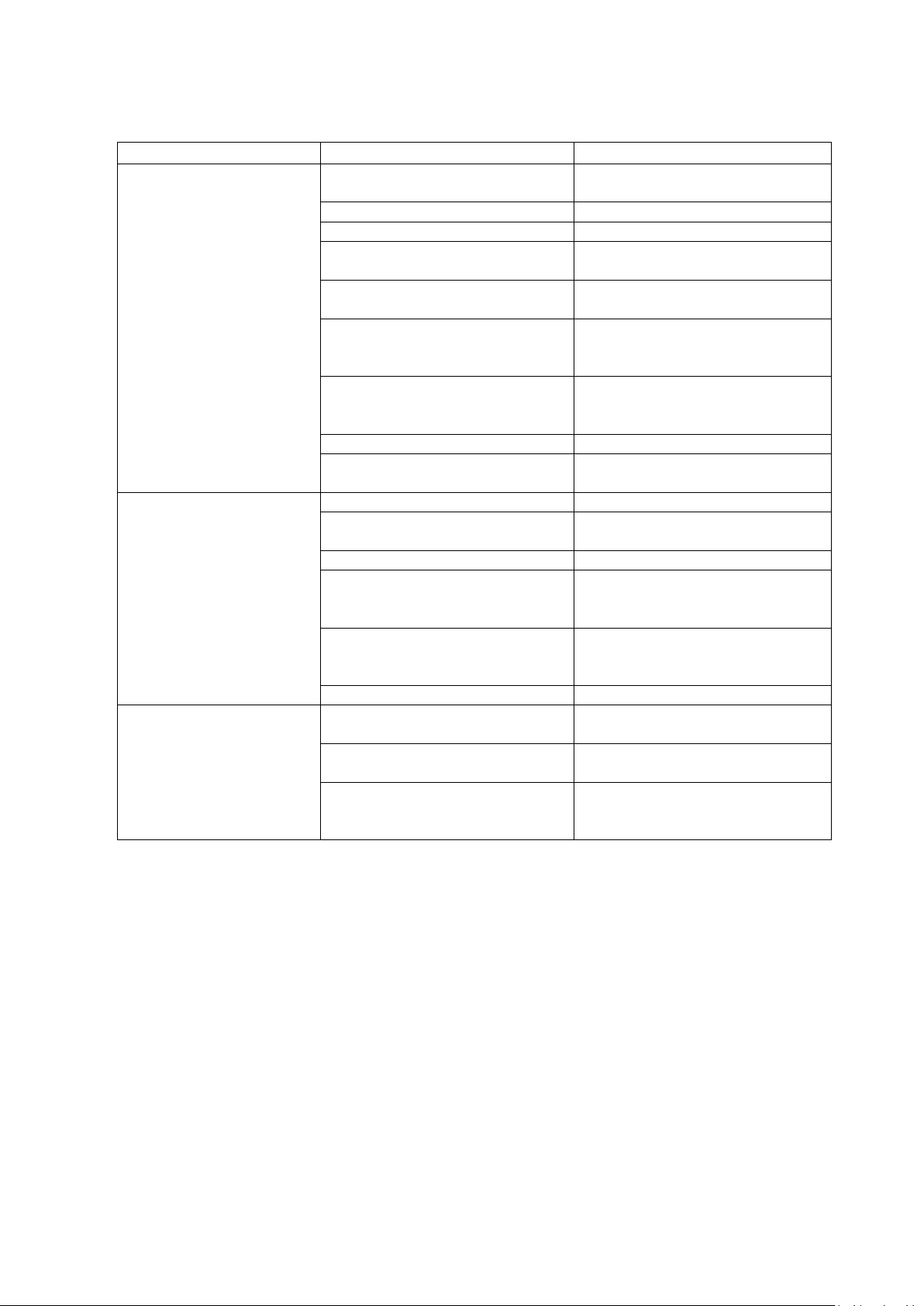
PN Body
material
Temperature °C
-10 …+50 100 150 200 250 300 350 400 450 500 530
Pressure MPa
16 0.7040 1,6 1,6 1,6 1,5 1,4 1,3 1,1
25 0.7040 2,5 2,5 2,4 2,3 2,2 2,0 1,8
40
1.0619
4,0
3,7
3,5
3,1
2,8
2,6
2,4
2,3
1.4408
4,0
3,7
3,4
3,1
2,9
2,8
2,7
2,6
63
1.0619
6,3
5,9
5,5
4,9
4,5
4,1
3,8
3,6
1.7357
6,3
6,3
6,3
6,3
6,2
5,7
5,3
5,0
4,8
3,8
2,2
100
1.0619
10,0
9,3
8,7
7,8
7,1
6,4
6,0
5,8
1.7357
10,0
10,0
10,0
10,0
9,8
9,1
8,4
8,0
7,6
6,1
3,5
1

4
2
DIMENSIONS
3 CONSTRUCTION DETAILS
Parts-
No.
Description
Parts-
No.
Description
1
Body
14
Cooling cylinder
2
Valve cover
15
Bolt
3
Gasket
16
Hexagon nut
4
Stud bolt
17
Control housing
5
Hexagon nut
18
Bonnet
6
Valve seat
19
Socket head screw
7
Cone
20
Pressure spring
8
Cone rod
21
Spring plate
9
Control piston
22
Adjusting screw
10
O-Ring
23
Hexagon nut
11
Locking screw
12
Guide sleeve
13
Gasket
Size Dimensions
(
mm
)
Dimensions
& Weights
L
L
Weight
(
kg
)
DN
DN PN16-40 H
H
Kvs
value 0.7040 1.0619 1.4408
h
h
PN63-100
15
20
25
32
40
50
65
80
100
125
150
200
82
66
66
81
83
100
113
140
154
210
235
285
1,8
3,2
5,0
7,9
13,0
20,0
34,0
51,0
80,0
130,0
180,0
320,0
11,4
11,4
12,5
14,5
16,0
35,0
39,5
52,5
68,0
150,0
180,0
330,0
12,0
12,0
13,0
16,0
18,0
37,5
43,0
58,0
77,0
155,0
190,0
385,0
12,0
12,0
13,0
16,0
18,0
37,5
43,0
58,0
77,0
155,0
190,0
385,0
130
150
160
180
200
230
290
310
350
210
230
230
260
260
300
340
380
430
400
480
600
410
586
615
733
762
715
720
950
5 2
1
7
6
8
9
4
3
16
12
15
14
17
18
13
10
19
11
23
20
21
22
2

5
up
4 INSTALLATION
WARNING
Pay very careful attention when working in hazardous environments. There is a risk of
explosion and the possibility of dangerous gases leaking. Always check whether the pipeline
contains flammable, high pressure or high temperature materials before starting to work.
Make sure that isolation valves are installed on both the upstream and downstream
lines.
CAUTION
Before installing the product, open both isolation valves and the bypass valve, if one exists, to
blow out any debris or dirt inside the pipeline. After blowing out the line, before starting to
work, close the isolation valves and allow time for the temperature to drop to a safe working
temperature.
When installing the product, be sure to leave clearance for maintaining it.
Installation Process
Remove the dustproof seals covering both connections (if existing).
Check the flow direction indicated on the side of the body.
The pressure reducing valve should be installed in a horizontal pipe
line with the cooling cylinder (No. 14) turned downwards, with
suitable bypass and isolating valves.
To prevent water hammer and vibrations caused by incoming
condensate it is necessary to install a steam trap before the pressure
reducing valve.
If you expect the average flow velocity to rise above 30m/sec, it is recommended to increase
the size of the pipe on the downstream side.
In case the pressure reducing ratio exceeds 25 : 1 , the pressure reduction is to be made in two
steps. In that case, a distance of at least 3 meters has to be kept between the two pressure
reducing valves.
The distance between the pressure reducing valve and a solenoid valve must be of at least 3
meters, if a solenoid valve with on/off function is installed upstream or downstream of the
pressure reducing valve. Otherwise, the pressure reducing valve may not function in a stable
way while the valve is opening or closing.
If a control valve is installed downstream of the pressure reducing valve, the distance between
the pressure reducing valve and the control valve must be of at least 2 meters. The disregard of
this recommendation may cause an unstable function of the pressure reducing valve as well.
To prevent an unusual rise of the secondary pressure a safety valve has to be installed to
protect the steam consuming equipment.
down
3

6
The pipe in which the pressure reducing valve is installed, must be fixed so that the weight and
the vibration of the pipe do not directly influence the pressure reducing valve.
Blow down the piping that leads to the PRV’s inlet from any dirt and scale before the first start-
up of the pressure reducing valve. This is particularly important in case of the start-up of the
pressure reducing valve after a long time of shut-down.
Before a long shut-down of the pressure reducing valve the condensate must be completely
discharged from the pipe. Furthermore the stop valves before and behind the pressure reducing
valve have to be closed.
The distance between the pressure reducing valve and a downstream pressure gauge should be
of at least 1 meter.
The length of the straight section of the upstream piping and the length of the straight section
of the downstream piping should be each at least 10 pipe diameters.
The steam trap and the pressure reducing valve should both be protected with a strainer. The
strainer should be installed in such a way that the screen will point sidewards to avoid the
accumulation of condensate in the area of the screen.
If you insulate the pressure reducing valve, do not insulate the cooling cylinder !!! The
insulation of the cooling cylinder prevents the built-up of condensate inside the cooling cylinder,
which is protecting the O-Rings. If there will be no condensate inside the cooling cylinder, the
O-Rings may be damaged !
Adjustment
The pressure reducing valve is usually preadjusted at the factory in accordance with the
instructions of the customer. As the real steam consumption and operating pressure may differ a
readjustment after installation under operating conditions is recommendable.
After the installation and before the adjustment of the pressure reducing valve close the stop valves
before and behind the pressure reducing valve and open the bypass to remove all condensate and
dirt from the pipe.
Close the bypass valve.
Open the stop valve downstream slightly. Then open the stop valve upstream slowly.
Now, open the stop valve downstream completely and check the set pressure.
To readjust the downstream pressure release the locking nut (No. 23). To increase the downstream
pressure turn the adjusting screw (No. 22) clockwise until the required pressure is reached. To
reduce the downstream pressure turn the adjusting screw counterclockwise until the required
pressure will be reached. After setting the downstream pressure, tighten the locking nut again.
In case of a shut-down of the equipment the stop valve downstream must be closed at first. The
stop valve upstream is to be closed as a second step. When the equipment will start up again open
the stop valve downstream at first and then open the stop valve upstream slowly.
4

7
5 MAINTENANCE
CAUTION
When replacing parts, make sure the replacement parts are supplied by Miyawaki.
Assemble and disassemble the valve after the internal pressure becoming the same as
the atmospheric pressure, and the surface temperature of the valve dropping enough
to prevent burning and serious injuries.
5.1. Remove the PRV from the pipe line
5.2. Fix the valve in a vice with the spring bonnet and adjust screw
showing upwards.
5.3. Untighten the locking nut (23) and unscrew it. Then turn the
adjusting screw (22) counterclockwise until the screw is moving
easily (no pressure exerting to the spring).
5.4. Untighten the 4 socket head screws (19) and remove them. Now
take off the bonnet (18) from the valve.
5.5. Remove the Spring plate (21) and the spring (20) from the valve.
5.6. Remove the valve from the vice and fix it again so that the flanges are showing upwards.
Untighten the hexagon nuts (5 - wrench size 17 mm) and remove the valve cover (2) from
the body. Remove also the cover gasket (3) and replace it by a new one.
5.7. Now again turn the valve to the former position when the cooling cylinder is showing
upwards. Untigten the locking screw with an impact driver (size 19 mm). After loosening
the locking screw (11) screw it out.
5

8
5.8. Caution !!
For DN15-DN40 (1/2”- 1 ½”) there is placed a small metal ring below the locking screw. Take
it out. Under the metal ring there are located small balls (12 pcs.). They are keeping the
cone rod (8) in its position. Remove these small balls carefully by turning the valve 180°. Pay
attention that the balls will not be lost.
5.9. Now remove the cone rod (8) from the valve body.
5.10. Remove the control piston (9) from the control housing (17). Replace the O-Ring (10) by a
new one.
5.11. Replacement of the gaskets between the cooling cylinder and body and between the cooling
cylinder and control housing
Untighten the hexagon nuts (16 - wrench size 15 mm) and unscrew them. Take off the valve
body from the cooling cylinder (14) and remove the cooling cylinder from the control
housing (17). Take off the guide sleeve (12) from the cooling cylinder. Check and clean the
openings in the guide sleeve. Replace the gaskets (13 –3 pcs.) by new ones.
5.12. Now reassemble the valve in the opposite way.
6

9
6 TROUBLESHOOTING
Problem
Cause
Solution
The downstream pressure
doesn't meet the set value.
It is too low.
Pressure was set incorrectly.
Turn the adjusting screw to correct the
setting of the secondary pressure.
The upstream stop valve is closed .
Open the valve.
The downstream stop valve is closed .
Open the valve.
The pressure gauge does not work
properly.
Replace the pressure gauge.
The steam amount upstream is too
small.
Check the steam amount by using a
bypass valve.
Insufficient capacity of the pressure
reducing valve. The size of the valve is
too small.
Check the real steam amount and the
capacity of the valve.
The screen of a strainer installed on
the inlet side of the pressure reducing
valve is plugged.
Clean the screen.
The O-Ring No.10 is leaking.
Replace by a new one.
The gasket of the valve cover (3) is
leaking.
Replace by a new one.
The downstream
pressure
exceeds the set pressure.
Pressure was not set correctly.
Turn the adjust screw to correct.
Inlet and outlet were installed the
wrong way round.
Install correctly according to the flow
direction.
The downstream stop valve is closed.
Open the stop valve.
The surface of the seat and/or valve is
damaged. The valve cannot close and
regulate the downstream pressure.
Check the valve and seat and judge
which parts must be replaced.
The openings in the guide sleeve (12)
are plugged. Steam cannot enter the
cooling cylinder.
Disaasemble the valve and clean the
guide sleeve.
The gaskets No. 13 are leaking.
Replace by new ones.
The secondary pressure is
fluctuating.
The inlet pressure is fluctuating.
Check the operating conditions on the
inlet side.
The steam consumption is fluctuating
strongly.
Check the downstream operating
conditions.
The steam consumption is exceeding
the capacity of the valve from time to
time.
Check the operating conditions and
select another size of the valve, if
necessary.
7

10
7 WARRANTY
7.1 Warranty period
The warranty period shall last 18 months from the date of product delivery, but not more than 12
months after the date of installation.
7.2 Details of the warranty
If the product stops working correctly within the warranty period, we will repair or
replace the product free of charge if the cause of the trouble is not one of the
following items:
The precautions described in this manual were not observed.
User's errors or mistakes such as an inappropriate installation or incorrect handling, or an
excessively large impact caused by dropping
Problems caused by devices or equipment other than ours, or a disallowed use
environment
When a repair or modification has been performed by anyone else than us or people who
are authorized to make such repairs
Intrusion of salt or other substances that promote significant rust or corrosion or problems
from fluids that contain the same substances
Extremely worn packing, gaskets, or other parts
Attachment or accumulation of foreign objects in the pipe, such as dust and scale
Problems from fires, natural disasters, or other force majeure which is not our
responsibility
7.3 Warranty limitation
The remedy available under the warranty shall not exceed the sales price of the products
delivered, for any cause whatsoever.
8

★
Guidance for reading special product name
○○○
-
○○
-
□
㻌
㻌
Special symbol: symbol apply only to special product
(Please refer to table 1 for details)
1 suffix English letter after “-“.
Model symbol: Product model number㻌
Table 1 Symbol description
Suffix
Special contents
A
Approved high-pressure gas trap
C
Blow valve attached & countermeasure against scale
K
Change of gasket
L
Special face to face dimension
M
㻌
Change of parts material
P㻌
Change of operating pressure
R
Change of screen mesh or countermeasure against scale
T㻌
Parts are standards, and the specification (operating temp, press.
etc.) is changed
V
Change of air vent
X
㻌
Other than mentioned above or complex of special contents above
9

For any questions about the product that you purchased or about the details in this user’s
manual, please contact the following.
© 2017 MIYAWAKI INC.
This user’s manual may not be reproduced or copied in whole or in part, without the
written consent of MIYAWAKI INC.
Some special specifications of the product you have, may found to be different from the
ones in the user's manual. If you have any question, please contact MIYAWAKI, our
local authorized agent, or the place where you purchased.

INTERNATIONAL SALES DEPT.
2-1-30, Tagawakita, Yodogawa-ku, Osaka, 532-0021, Japan
Tel: +81-6-6302-5549
www.miyawaki.net e-mail: [email protected]
EU Importer and Authorized representative:
MIYAWAKI GmbH
Birnbaumsmühle 65, 15234 Frankfurt (Oder), Germany
Tel: +49-335-4007-0097
www.miyawaki.net e-mail: info@miyawaki.de
China Importer and Authorized representative:
MIYAWAKI WEST Co.,ltd
Room 1705, No.1, Building,No.311, Yanxin Road, Huishan Economic Development Zone,
Wuxi, Jiangsu, China
Tel: +86-510-8359-5125
www.miyawaki-inc.com.cn e-mail: [email protected]n
OM No.E-R07-03 1605
RE20 15-40
Table of contents
Other MIYAWAKI Control Unit manuals
Popular Control Unit manuals by other brands

Baker Hughes
Baker Hughes Masoneilan 41005 Series instruction manual

National Instruments
National Instruments Module SCXI-1125 CALIBRATION PROCEDURE

Simex
Simex SIN-8 user manual

Inovance
Inovance IMC30-6G Series Hardware manual

Acorn Engineering
Acorn Engineering SFST-T-OT-ITG Installation, operation and maintenance instructions

MicRadar
MicRadar R60AFD2 Using Guide