6
The pipe in which the pressure reducing valve is installed, must be fixed so that the weight and
the vibration of the pipe do not directly influence the pressure reducing valve.
Blow down the piping that leads to the PRV’s inlet from any dirt and scale before the first start-
up of the pressure reducing valve. This is particularly important in case of the start-up of the
pressure reducing valve after a long time of shut-down.
Before a long shut-down of the pressure reducing valve the condensate must be completely
discharged from the pipe. Furthermore the stop valves before and behind the pressure reducing
valve have to be closed.
The distance between the pressure reducing valve and a downstream pressure gauge should be
of at least 1 meter.
The length of the straight section of the upstream piping and the length of the straight section
of the downstream piping should be each at least 10 pipe diameters.
The steam trap and the pressure reducing valve should both be protected with a strainer. The
strainer should be installed in such a way that the screen will point sidewards to avoid the
accumulation of condensate in the area of the screen.
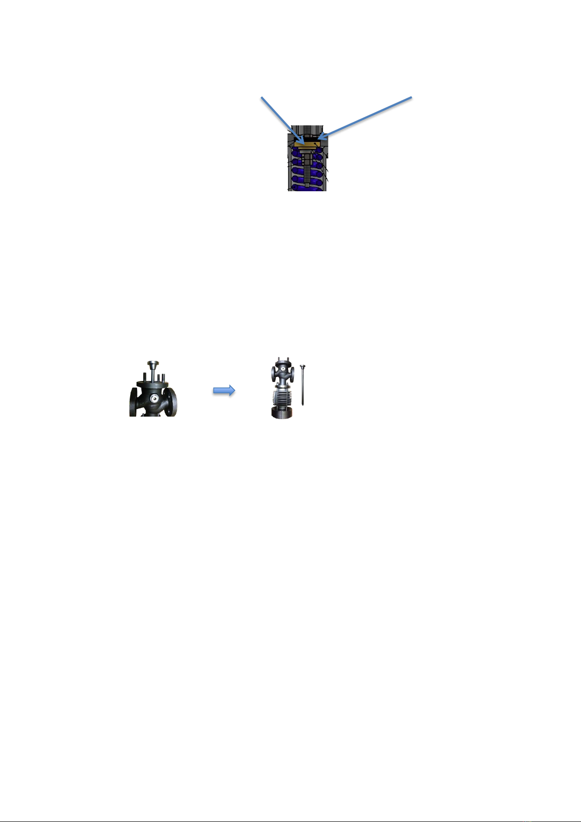
If you insulate the pressure reducing valve, do not insulate the cooling cylinder !!! The
insulation of the cooling cylinder prevents the built-up of condensate inside the cooling cylinder,
which is protecting the O-Rings. If there will be no condensate inside the cooling cylinder, the
O-Rings may be damaged !
Adjustment
The pressure reducing valve is usually preadjusted at the factory in accordance with the
instructions of the customer. As the real steam consumption and operating pressure may differ a
readjustment after installation under operating conditions is recommendable.
After the installation and before the adjustment of the pressure reducing valve close the stop valves
before and behind the pressure reducing valve and open the bypass to remove all condensate and
dirt from the pipe.
Close the bypass valve.
Open the stop valve downstream slightly. Then open the stop valve upstream slowly.
Now, open the stop valve downstream completely and check the set pressure.
To readjust the downstream pressure release the locking nut (No. 26 for DN50-65; No.27 for DN80-
100). To increase the downstream pressure turn the adjusting screw (No. 25 for DN50-65; No.26 for
DN80-100) clockwise until the required pressure is reached. To reduce the downstream pressure
turn the adjusting screw counterclockwise until the required pressure will be reached. After setting
the downstream pressure, tighten the locking nut again.
In case of a shut-down of the equipment the stop valve downstream must be closed at first. The
stop valve upstream is to be closed as a second step. When the equipment will start up again open
the stop valve downstream at first and then open the stop valve upstream slowly.
4