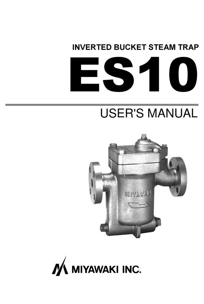
MIYAWAKI ESH21 User manual

INVERTED BUCKET STEAM TRAP
ESH21
USER'S MANUAL

SAFETY GUIDE
The model ESH21 is a cast steel inverted bucket steam trap for medium
condensate loads and medium up to high pressure applications.
In order to get maximum benefit from this product, be sure to read this
manual before installing it.
The following warnings and cautions are shown at appropriate
places in this manual.
WARNING
Failure to observe this type of precaution may
lead to serious injury or death.
CAUTION
Failure to follow this type of precaution can
lead to injury or damage to equipment and
property.
Table of Contents
1 SPECIFICATIONS AND MARKINGS
1
2 CONSTRUCTION DETAILS
2
3 INSTALLATION
3
4 OPERATION
5
5 MAINTENANCE
6
6 TROUBLESHOOTING
10
7 WARRANTY
11
8 SERIAL NUMBER (S. No.) DESIGNATION
12
9 GUIDANCE FOR READING SPECIAL PRODUCT
NAME
13

1
1SPECIFICATIONS AND MARKINGS
WARNING
Be sure not to use this product at higher pressures than the specified maximum
allowable pressure (PMA) or at temperatures higher than the specified maximum
allowable temperature (TMA).
Check the operating characteristics to avoid misuse of the product.
1) Maximum allowable pressure (PMA): 4.4 MPa (640 psig)
2) Maximum allowable temperature (TMA): 400 °C (752 °F)
3) Maximum operating pressure (PMO): ESH21(W,F) - 21 2.1 MPa (305 psig)
(Shown as MAX.P. on the name plate) ESH21(W,F) - 45 4.4 MPa (640 psig)
4) Maximum operating temperature (TMO): 400 °C (752 °F)
(Shown as MAX.T. on the name plate)
5) Size: 15 – 25 mm (1/2” – 1”)
6) Year of production: The two leftmost digits in the four-digit or nine-digit 'S. No.' are
the last two digits of the year of production (see remarks on page 12).
7) Flow direction: Shown by an arrow
8) Body material: Cast steel SCPH2
9) Model: Showing the product model name
Some pictures and illustrations in this manual are examples of the ESH21 model. For more details
regarding dimensions and other specifications, please refer to the catalog.
The model ESH21 fully complies with the requirements of the European Pressure
Equipment Directive 2014/68/EU. The model ESH21 is classified according to Article 13
and Annex II of the PED by category I of the Fluid Group 2. The CE marking is affixed to
the products.

2
2CONSTRUCTION DETAILS
1. Body
2. Cover
3. Screen Plug
4. Cover Plug
5. Valve Seat
6. Valve
7. Valve Holder
8. Pin
9. Bucket
10. Eyebolt
11. Pipe
12. Eyebolt Pin
13. Lever
14. Bracket
15. Pin
16. Set Bolt
17. Screen
18. Name Plate
19. Rivet
20. Cover Bolt
21. Cover Gasket
22. Spacer
23. C-Ring
24. Body Plug
25. Body Plug
26. Seat Gasket
27. U-Nut
28. Pipe
29. Pin

3
3INSTALLATION
WARNING
Pay very careful attention when working in hazardous environments. There is a risk
of explosion and the possibility of dangerous gases leaking. Always check whether
the pipeline contains flammable, high pressure or high temperature materials
before starting to work.
Make sure that isolation valves are installed on both the upstream and downstream
lines.
CAUTION
Before installing the product, open both isolation valves and the bypass valve, if
one exists, to blow out any debris or dirt inside the pipeline. After blowing out the
line, before starting to work, close the isolation valves and allow time for the
temperature to drop to a safe working temperature.
When installing the product, be sure to leave clearance for maintaining it.
Clearance for
maintenance:
More than 230 mm
Downstream
line
Upstream
line
Name Plate
Flow direction is
indicated by an
arrow.
Clearance for
maintenance:
More than 110 mm

4
1) Remove the dustproof seals covering both connections.
※Products shipped in plastic bags may not have dustproof seals.
2) Check the flow direction indicated on the body.
3) When installing the model ESH21, install it so that the flow from the upstream line to
the downstream line is horizontal and the name plate is on the top side of the body.
When installing the trap in a horizontal line, be sure to maintain a slight slope of the
line, so that any condensate will flow smoothly to the trap.
4) Open the isolation valve on the upstream line slowly and make sure the product works
normally.
※Install the trap at a lower position than the equipment that generates condensate.
※If the trap is installed higher than the steam using equipment, please install a lift fitting
as shown in drawing B for better performance.
CAUTION
If installed on a cylinder dryer, please install lower than the lowest point of the
cylinder and minimize the horizontal piping.
Lift Fitting
One size smaller
Heat Exchanger
Trap
Condensate Tank
Branch Line
Recovery Main
Check Valve
Drawing A
Drawing B
Trap

5
4OPERATION
CAUTION
Before starting operation, open the bypass valve or blow valve completely and blow
off the scale in the piping.
4.1 Operation procedure
1) After blowing off the scale from the piping, close the bypass valve or blow valve.
2) Open the stop valve on the trap outlet side.
3) Open the stop valve on the trap inlet side.
4.2 Stop procedure
1) Close the stop valve on the trap inlet side.
2) Close the stop valve on the trap outlet side.
* When stopping for a long time, completely drain the condensate from the piping and trap
and close the valves before and after the trap.

6
5MAINTENANCE
WARNING
Before removing the trap from the pipe or disassembling it, be sure to close the
isolation valves. Then, release the residual pressure from the trap body (make
sure that the pressure in the main body is equal to the atmospheric pressure).
After it has fully cooled down (after the temperature of the main body has
reached ambient temperature), confirm for safe conditions and then begin to
work.
Even when the isolation valves are closed, there may be residual internal
pressure due to leaks from the isolation valves. Therefore, be very careful.
CAUTION
When replacing parts, make sure the replacement parts are supplied by
MIYAWAKI.
The performance of steam traps deteriorates gradually over time due to wear, corrosion
or dirt accumulating around the valve and the valve seat. Please conduct periodic
diagnosis of traps in order to keep steam control systems and equipment working well.
5.1 Tools for Diagnosing Steam Traps
Dr. Trap
Dr. Trap is a sophisticated steam trap management system for diagnosing steam traps
automatically by measuring the vibration and temperature of the steam trap. Survey
results are stored in the testing equipment and transferred to a steam trap analysis
software. The software aggregates and analyses steam trap survey data, identifying
faulty steam traps, providing steam loss and financial loss data, estimating CO2 emissions
corresponding to leaking steam traps and providing many other analyze possibilities to
manage the steam trap population easily.
Dr. Trap Jr.
Dr. Trap Jr. is an inexpensive and easily to handle steam trap diagnostic system
consisting of an ultrasonic checker, temperature probe and a sophisticated analysis
software. The software allows to determine the condition of a steam trap, to estimate
steam and financial losses and the related CO2 emissions.
For more details, please, check our homepage:
https://www.miyawaki.net/en/products/steam-trap-management-system
or ask our local representative.

7
5.2 Repairs
When a trap fails, it is necessary to clean the internal parts and to replace damaged parts.
Take the failed trap apart following the steps below.
5.2.1 Disassembling the trap
1) Untighten the screen plug (3), take out the screen (17), check and clean it.
2) Unscrew the cover bolts (20) and remove the cover (2) from the body (1).
3) The internal unit and bucket (9) can be removed while connected to the cover (2).
4) When the pin (15) has been pulled out, the valve (6), valve holder (7), pin (8), bucket
(9), eyebolt (10), eyebolt pin (12), U-nut (27), pin (29) and lever (13) can be removed
together from the cover (2).
5) Unscrew the set bolt (16), take off the c-ring (23) from the valve seat (5), take off the
bracket (14) and remove the valve seat (5) and the seat gasket (26).
6) Take off the pin (8). The valve (6) and valve holder (7) come apart from the lever (13).
※Basically, there is no need to disassemble as the valve unit can be purchased as a
complete unit. But, if you disassemble the parts, replace the pin (8) with a new one.
7) Remove the cover gasket (21) and clean the sealing surfaces of the body (1) and
cover (2).
CAUTION
Clean the Body (1) and Cover (2) with care not to damage the sealing surface.
Scratches on the sealing surface may cause steam leakage.
Take appropriate measures according to “6. Troubleshooting”. After cleaning the trap and
replacing damaged parts, re-assemble the parts in reverse order as follows. Refer to the
torque table for each part.
5.2.2 Reassembling the trap
1) Attach the seat gasket (26) and valve seat (5) to the cover (2).
2) Insert the set bolt (16) into the hole in the bracket (14) and insert the spacer (22) into
the set bolt (16).
* Check the exploded view and be careful not to make a mistake in the orientation of
the bracket (14).
Insert the tip of the valve seat (5) into the other hole in the bracket (14) and attach the
set bolt (16) to the cover (2).
Attach the C-ring (23) to the tip of the valve seat (5) to secure the bracket (14).
3) Attach the valve holder (7) to the lever (13), insert the valve (6) into the valve holder
(7), and attach the pin (8) to the valve holder (7).
After bending the tip of the pin (8), check that the valve holder (7) can be rotated 360°
lightly.

8
4) Connect the internal unit removed from the cover (2) to the cover with the pin (15).
5) If there are loose threads on the internal unit, be sure to tighten them.
6) Place the cover gasket (21) on the sealing surface of the body (1). At this time, be
careful not to displace the outlet passage hole of the cover gasket (21) and the body
(1).
7) Install the cover (2) with the internal unit on the body (1) and tighten the cover bolts
(20). At this time, be careful that the outlet passage holes in the body (1) and cover
(2) do not shift.
8) Put the screen (17) into the body (1) and tighten the screen plug (3).
Torque table
Parts
Tools
Across the flats
Torque
Valve Seat (5)
Torque Wrench
23 mm (0.91”)
120 N∙m
Set Bolt (16)
Torque Wrench
13 mm (0.51”)
21 N∙m
Cover Bolt (20)
Torque Wrench
24 mm (0.95”)
250 N∙m
CAUTION
When reassembling always replace the cover gasket (21) and seat gasket (26) with
new ones. Tighten the cover bolts (20) evenly crosswise.

9
4. Cover Plug
11. Pipe
15. Pin
25. Body Plug
2. Cover
6. Valve
7. Valve Holder
5. Valve Seat
21. Cover Gasket
23. C-Ring
29. Pin
14. Bracket
9. Bucket
1. Body
3. Screen Plug
17. Screen
20. Cover Bolt
13. Lever
18. Name Plate
10. Eyebolt
19. Rivet
26. Seat Gasket
22. Spacer
27. U-Nut
16. Set Bolt
24. Body Plug
8. Pin
28. Pipe
12. Eyebolt Pin

10
6TROUBLESHOOTING
Problem
Possible cause
Solution
Steam leaks or blows
through.
The condensate amount in the
body (1) is extremely small,
and the valve opening state
continues due to the sinking of
the bucket (9).
Remove the cover plug (4)
and pour water into the body
(1).
A foreign object is caught
between the valve (6) and the
valve seat (5).
Disassemble and clean the
valve (6) and valve seat (5).
*1
The valve (6) and valve seat
(5) are damaged.
Replace the valve unit with a
new one.
The bucket (9) has dropped
out with the valve open.
Disassemble and install
bucket (9) correctly.
Steam leaks
from the
body.
From the
connection
between the
body and
cover
The cover bolts (20) are loose.
Tighten the cover bolts (20).
*2
The cover gasket (21) is
damaged.
Replace the cover gasket
(21).
Insufficient condensate
discharged, or no
condensate discharged.
Steam pressure exceeds the
trap specification.
Reduce steam pressure or
replace with high pressure
trap.
Insufficient condensate
capacity.
Replace the trap with a larger
capacity trap.
Plugged air vent hole in the
bucket (9).
Clean the air vent hole in the
bucket (9).
Dirt has built up on or around
the valve seat (5).
Clean the valve seat (5).
The bucket (9) has dropped
out with the valve close.
Disassemble and install
bucket (9) correctly.
*1 and *2: Refer to the torque table in Section 5, “Maintenance” to retighten the parts with
the correct torque.

11
7WARRANTY
7.1 Warranty period
The warranty period is 18 months after shipment or 12 months after installation, whichever
occurs first.
7.2 Details of the warranty
If the product stops working correctly within the warranty period, we will repair or replace
the product free of charge if the cause of the trouble is not one of the following items.
1) The precautions described in this manual were not observed.
2) User's errors or mistakes such as an inappropriate installation or incorrect handling,
or an excessively large impact caused by dropping
3) Problems caused by devices or equipment other than MIYAWAKI’s, or a disallowed
use environment
4) When a repair or modification has been performed by anyone other than MIYAWAKI
or people who are authorized to make such repairs
5) Intrusion of salt or other substances that promote significant rust or corrosion or
problems from fluids that contain the same substances
6) Consumable parts such as Packing, Gasket, O-ring, Diaphragm, etc.
7) Attachment or accumulation of foreign matter in the pipe, such as dust and scale
8) Problems from fires, natural disasters, or other force majeure which is not
MIYAWAKI’s responsibility
7.3 Warranty limitation
The remedy available under the warranty shall not exceed the sales price of the products
delivered, for any cause whatsoever.

12
8SERIAL NUMBER (S. No.) DESIGNATION
The following 4-digit or 9-digit ’S.No.' is displayed on the product.
● For 4-digit display
S.No. □□□□
Represents the day.
Represents the month.
Represents the year. (last two digits of the
year according to the Western calendar)
● For 9-digit display
S.No. □□□□□□□□□
MIYAWAKI identification number
Represents the month.
Represents the year. (last two digits of the
year according to the Western calendar)
Month designation system
Month
1
2
3
4
5
6
7
8
9
10
11
12
Symbol
1
2
3
4
5
6
7
8
9
X
Y
Z
Day designation system
Day
1
2
3
4
5
6
7
8
9
10
11
12
Symbol
1
2
3
4
5
6
7
8
9
A
B
C
Day
13
14
15
16
17
18
19
20
21
22
23
24
Symbol
D
E
F
G
H
J
K
L
M
N
O
P
Day
25
26
27
28
29
30
31
Symbol
Q
R
S
T
U
V
W
Example of serial number designation
1711 → Jan.1, 2017
29XM → Oct. 21, 2029
Example of serial number designation
17112C020→ Jan., 2017
29X05M050 → Oct., 2029

13
9GUIDANCE FOR READING SPECIAL PRODUCT
NAME
〇〇〇-○○-□
Special symbol:
The symbol applies only to
special products
(Please refer to table 1 for details)
Model symbol:
Product model number
Table 1 Symbol description
Suffix
Special contents
A
Trap for high-pressure gas installed property (only for Gas Trap)
C
Blow valve attached
K
Change of gasket
L
Special face to face dimension
M
Change of parts material
P, T
Change of operating pressure, temperature, condensate capacity, etc
R
Change of screen mesh
V
Change of air vent
X
Other than mentioned above or complex of special contents above

________________________________________
お買い上げの製品及びこの取扱説明書内容についてのご質問は下記にお問い合わせく
ださい。また、この取扱説明書を紛失したり、汚損により読めなくなった場合は、同
じく下記へご請求ください。
特殊仕様の製品については、取扱説明書の内容と一部異なる場合があります。特殊仕
様に関する取扱説明書内容についてのご質問は、お買い上げ頂いた販売店若しくは最
寄の弊社ミヤワキまでお問い合わせください。
外観及び仕様などは、製品改良のため予告なしに一部変更させて頂くことがありま
す。
For any questions about the product that you purchased or about the details in this
user’s manual, please contact the following.
© 2020 MIYAWAKI INC.
This user’s manual may not be reproduced or copied in whole or in part, without the
written consent of MIYAWAKI INC.
Some special specifications of the product may found to be different from the ones in
the user's manual. If you have any question, please contact MIYAWAKI, our local
authorized agent, or the company where you purchased the product.
In the interest of the development and improvement of our products, MIYAWAKI Inc.
reserves the right to change the specification of the products without prior notice.
________________________________________

お問い合わせ窓口
製品の使い方やアフターサポートなど、製品に関するお問い合わせ
は、右の QR コードから、最寄りの弊社事業所までご連絡ください。
弊社事業所一覧(連絡先)は右の QR コードをスマートフォン、
携帯電話等で読み取っていただくことでアクセスできます。
本社・工場
〒532-0021 大阪市淀川区田川北 2-1-30
Tel:06-6302-5531(代)
www.miyawaki-inc.com
INTERNATIONAL SALES DEPT.
2-1-30, Tagawakita, Yodogawa-ku, Osaka, 532-0021, Japan
Tel: +81-6-6302-5549
www.miyawaki.net e-mail: export@miyawaki-inc.co.jp
EU Importer and Authorized representative:
MIYAWAKI GmbH
Birnbaumsmühle 65, 15234 Frankfurt (Oder), Germany
Tel: +49-335-4007-0097
www.miyawaki.net e-mail: info@miyawaki.de
China Importer and Authorized representative:
MIYAWAKI WEST Co., Ltd.
Room 1705, No.1, Building No.311, Yanxin Road, Huishan Economic Development Zone,
Wuxi, Jiangsu, China
Tel: +86-510-8359-5125
www.miyawaki-inc.com.cn e-mail: [email protected]
808074-01 2012
ESH21
Table of contents
Other MIYAWAKI Plumbing Product manuals
Popular Plumbing Product manuals by other brands

Kohler
Kohler K-7273 Installation and care guide

Moen
Moen T911 Series manual

Franke
Franke F5 Series Installation and operating instructions

T&S
T&S EVERSTEEL S-1200 Series Installation and maintenance instructions

American Standard
American Standard 4" Centerset Lavatory and Bar Sink Faucets 5400... installation instructions

newform
newform 69671EX instructions

Hans Grohe
Hans Grohe Croma 220 Air 1jet 26465000 Assembly instructions

Danze
Danze D304658 installation instructions

Blanco
Blanco TRADON HD 520787 INSTALLATION AND CARE INSTRUCTIONS

miseno
miseno MNO5882CP quick start guide

newform
newform BLINK 70835 instructions

Mora armatur
Mora armatur Izzy S1 instructions