MK ExLRT User manual


OPERATOR MANUAL EXLRT
Ref: XLR-104 © 2020 MK Test Systems Ltd Page 2 of 28
OPERATOR MANUAL
EXLRT
XLR-104-1
Author:
Giuseppe Prisco Date:
12th December 2019
Reviewed:
Jamie Spiller Date:
5th February 2020
Approved:
Alan Wilson Date:
6th February 2020

OPERATOR MANUAL EXLRT
Ref: XLR-104 © 2020 MK Test Systems Ltd Page 3 of 28
MODIFICATIONS
Revision Date Modified by Changes / ECR
1 6th February 2020 Giuseppe Prisco First Release
Pictures, graphics, formatting, and/or detail that describes the functionality is subject to change
to the discretion of MK Test Systems Ltd
MK Test Systems Ltd believes the information described in this safety manual to be accurate and
reliable. However, no responsibility, financial or otherwise, is accepted for any consequence arising
out of the use of the information contained within this safety manual.
The information contained within the safety manual is the property of MK Test Systems Ltd, and
reproduction in whole or part shall not be undertaken in any form, by any means, for any purpose
without written authorisation from MK Test Systems Ltd.
In no event shall MK Test Systems Ltd be liable to anyone or body for special, collateral, incidental
or consequential damages or losses with or arising out of the use MK Test Systems Ltd products.
The information contained within the safety manual is subject to change at any time without prior
notice.
MK Test Systems Ltd reserves the right to revise and improve its products as it sees fit.

OPERATOR MANUAL EXLRT
Ref: XLR-104 © 2020 MK Test Systems Ltd Page 4 of 28
Table of Contents
1 Introduction ................................................................................................................................................. 5
2 Hardware ..................................................................................................................................................... 6
Product overview ................................................................................................................................. 6
ExLRT Overview .................................................................................................................................... 7
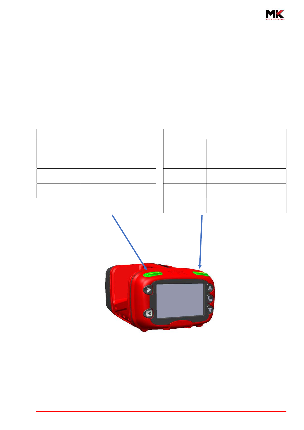
Buttons ................................................................................................................................................. 8
Indicators ............................................................................................................................................. 8
3 Charging the battery .................................................................................................................................... 9
External charging ................................................................................................................................. 9
Internal Charging .................................................................................................................................. 9
4 Using the ExLRT .......................................................................................................................................... 10
Calibration .......................................................................................................................................... 10
5 Using the integrated self-test fixture ......................................................................................................... 11
6 Functions and features .............................................................................................................................. 12
LCD display ......................................................................................................................................... 12
7-Segment Display and Icons description .......................................................................................... 13
7 Start-up (Power on) ................................................................................................................................... 14
Login (Option) .................................................................................................................................... 14
8 Main Menu ................................................................................................................................................. 15
9 Manual Menu ............................................................................................................................................. 16
Manual measurement modes ............................................................................................................ 17
Overview .................................................................................................................................... 17
10 Continuous mode measurements ............................................................................................................. 18
Starting Continuous ........................................................................................................................... 18
Pausing continuous mode measurements ......................................................................................... 18
Resuming continuous mode .............................................................................................................. 18
Exiting from continuous mode ........................................................................................................... 18
Averaging ........................................................................................................................................... 19
Triggering ........................................................................................................................................... 20
11 Single Shot Measurements ........................................................................................................................ 21
Initiating a single shot test ................................................................................................................. 21
Taking a measurement....................................................................................................................... 22
Exit from single shot mode ................................................................................................................ 22
12 Stray current .............................................................................................................................................. 22
13 INFORMATION MENU ................................................................................................................................ 23
14 ExLRT Unit .................................................................................................................................................. 23
15 Cable .......................................................................................................................................................... 23
16 Calibration Information ............................................................................................................................. 24
17 Settings Menu ............................................................................................................................................ 24
18 Measurement............................................................................................................................................. 25
Averaging? ......................................................................................................................................... 25
Trigger on Percentage? ...................................................................................................................... 25
Trigger on Value? ............................................................................................................................... 25
Change trigger values? ....................................................................................................................... 26
Change % of reading .................................................................................................................. 26
19 Calibration .................................................................................................................................................. 28
20 System ........................................................................................................................................................ 28
21 Calibration Verification .............................................................................................................................. 28

OPERATOR MANUAL EXLRT
Ref: XLR-104 © 2020 MK Test Systems Ltd Page 5 of 28
1 INTRODUCTION
This manual is provided to the end user to understand the operation of the ExLRT and its associated
components.
This manual does not include safety information for the ExLRT
Refer to document XLR-927
Do not operate the ExLRT without reading and understanding the Safety Manual.
The manual does not include servicing or repair literature.
There are no user serviceable parts.

OPERATOR MANUAL EXLRT
Ref: XLR-104 © 2020 MK Test Systems Ltd Page 6 of 28
2 HARDWARE
Product overview
The ExLRT is a battery-operated device that is designed to measure the resistance of complex
constructed loops for the use of electrically bonding parts within structures and sub-frames. It has an
additional joint mode that can measure the bond joints within the loops.
The ExLRT uses current couplers that non-intrusively couple an AC signal into the loop. A drive coupler
is used to inject the signal with a known voltage and a second coupler is used to measure the current.
To measure individual joints within the loop, a pair of joint probes are used to measure the voltage
presented across the joint resistance. Knowing the voltage and current for each test, the ExLRT
calculates the resistance.
ExLRT
Battery
Charger
AC-DC Power Supply
Loop Cable
Joint Cable

OPERATOR MANUAL EXLRT
Ref: XLR-104 © 2020 MK Test Systems Ltd Page 7 of 28
ExLRT Overview
Power input
Joint Connector
Power-on button
USB Connector
Loop Connector
LCD Display
Joint status
indicator
Loop status
indicator
Battery
compartment
Self-test
Buttons
Buttons

OPERATOR MANUAL EXLRT
Ref: XLR-104 © 2020 MK Test Systems Ltd Page 8 of 28
Buttons
Five buttons serve the following main functions
1) Start and Stop measurements in manual mode
2) Browse menus
3) Change/Set parameters
Indicators
Two indicators are situated on the top of the ExLRT. The left indicator shows the status of the loop
measurement and the right indicator shows the status of the joint measurements. The indicators act
as repeaters to the LEDs situated on the Loop and Joint cables.
The indicator colours identify the following test status.
Loop status indication
Joint status indication
Green Flashing Waiting for loop test to
commence Green Flashing Waiting for user to connect joint
probes to UUT
Amber ON Loop test measuring Amber ON Joint test measuring
Amber Flashing Paused State
(Continuous mode only) Amber Flashing Paused State
(Continuous mode only)
Red flashing
Loop test error
Red flashing
Joint test error
Drive/Sense Coupler open Joint test intermittent

OPERATOR MANUAL EXLRT
Ref: XLR-104 © 2020 MK Test Systems Ltd Page 9 of 28
3 CHARGING THE BATTERY
External charging
Insert the battery into the charger as shown and attach the supplied MK PSU. The table below shows
the list of the LED states to indicate the state of the battery.
Charger State
(Normal working condition) LED 1 (Left) LED 2 (Right)
Ready to Charge (Battery not installed)
Off Green
Charging Red Green
Battery Inserted and fully Charged Off Green
NiMH Top-Off Charge/Charged Orange Green
Internal Charging
Simply plug the PSU into the ExLRT to charge the battery. The battery container will display flashing
bars to indicate that the battery is charging.

OPERATOR MANUAL EXLRT
Ref: XLR-104 © 2020 MK Test Systems Ltd Page 10 of 28
4 USING THE EXLRT
Calibration
Calibration Verification is a method to verify the ExLRT instrumentation hardware to calibrated
standards. Adjustment is performed using MK PC software and is run by a user with appropriate
permissions. Once the verification is performed and the ExLRT has passed, the ExLRT and will display
the icon when the correct combination of cables are connected to the ExLRT.
Calibration Warning Date:
This is set within the PC ExLRT software at the time of verification. It is used as a warning to the user
when the ExLRT is due for calibration.
Calibration Expiry Date:
This is set within the PC ExLRT software at the time of verification. the Calibration will expiry once the
expiry has elapsed.

OPERATOR MANUAL EXLRT
Ref: XLR-104 © 2020 MK Test Systems Ltd Page 11 of 28
5 USING THE INTEGRATED SELF-TEST FIXTURE
The ExLRT has an integrated Self-Test fixture. To test the ExLRT instrumentation, simply connect the
loop and joint cables to the ExLRT and clamp the loop couplers around the handles as shown.
NOTE:
The Self-Test fixture is manufactured out of stainless steel and is not intended to be used as
calibrated. The designed nominal value is 9.5mΩ but expect to see small deviations in measurement
for each ExLRT manufactured. MK does not hold itself responsible if the Self-Test Loop yields a
measurement outside of the tolerance due to poor care or attention of the ExLRT.
Typical loop value
9.5mΩ (+/-0.5mΩ).
Navigate through the menus to the
measurement screen and take a
loop test.
Typical joint value
8mΩ (+/-0.5mΩ)
To take a high value joint test,
connect the joint probes to the outer
points.
Typical joint value
0.2mΩ (+/-0.1mΩ)
To take a low value joint test,
connect the joint probes to the inner
points.

OPERATOR MANUAL EXLRT
Ref: XLR-104 © 2020 MK Test Systems Ltd Page 12 of 28
6 FUNCTIONS AND FEATURES
The ExLRT provides the following functions and features
Manual Measurements (Two modes: Continuous and Single Shot)
Measures the resistances of loops and joints
User interface providing responsive status and error messaging to the user
Supports multiple users
Login using user ID and Password
Up to 32 users (Setup with permissions/restrictions)
Up to 15 user configurations (one allocated for Customer Administrator)
Icons showing the following status’ during operation
Calibration
Battery life (including charging status)
Configuration Level in use
Measurement mode and settings
Date and Time
Connection to PC via USB
LCD display
The LCD is split into the following sections
1
.
Dot Matrix
display
Icons
Subtest
information
7-Segment display
Loop and Joint
Date/Time
Icons

OPERATOR MANUAL EXLRT
Ref: XLR-104 © 2020 MK Test Systems Ltd Page 13 of 28
7-Segment Display and Icons description
Loop or Joint measurement
Date and Time
Sequence number (Maximum of 999 subtests per test program)
Loop Cable Connect Appears when the loop cable is connected to the ExLRT
Joint Cable Connect Appears when the joint cable is connected to the ExLRT
Link Displayed if software has established a handshaking to the PC software either via
USB or Bluetooth
Cable Displayed if the ExLRT has detected a cable
Locked Displayed if the ExLRT has expired its calibration. The icon is used to indicate to
the user that ExLRT is not able perform measurements
Unlocked Displayed if the user type is super user or has permissions to perform
measurement if the ExLRT is not calibrated
Configuration Level of configuration is displayed depending on user permissions
Calibrated Displayed when the has been Calibrated and has its associated verified cables are
connected
Not Calibrated Displayed when the ExLRT is within calibration expiry but has at least one wrong
cable plugged in
Single shot Displayed when the ExLRT is taking a single shot measurement
Continuous Displayed when the ExLRT is taking a continuous measurement
Averaging Displayed when averaging mode is enabled (Available in continuous mode)
Trigger Displayed when triggering is enabled (Available in continuous mode)
Averaging and
Trigger Displayed when both averaging and triggering is enabled
Self-Test Displayed if internal self-test has passed
Flashing Flashing if internal self-test has failed
Battery life Shows battery charge level
Charging
While charging, the battery container and bars will flash. The bars will also
‘increment’ as the battery is charging
CFG
1234

OPERATOR MANUAL EXLRT
Ref: XLR-104 © 2020 MK Test Systems Ltd Page 14 of 28
7 START-UP (POWER ON)
To power on, press the button on the rear of the front panel. The ExLRT will start up and briefly
display the following information
Login (Option)
If enabled, the ExLRT will present the Log On screen. If Log On is not enabled, then the ExLRT will
proceed straight to the ExLRT main menu. See section 8 Main Menu. See document XLR-105 Section
- ExLRT Device Settings to how to configure Log On
Enter User ID
If login is enabled at start-up, then the ExLRT will prompt for a user ID as follows.
Upon entry of a recognised user ID, the ExLRT will advance to prompt for a Password as soon as the
fifth correct digit has been entered. Below shows an example of the user ID being entered.
Password entry
If the password has been incorrectly entered three times, the ExLRT will return to the user ID entry
screen.

OPERATOR MANUAL EXLRT
Ref: XLR-104 © 2020 MK Test Systems Ltd Page 15 of 28
8 MAIN MENU
The following options are listed in the main menu. Use the scroll up and down buttons to highlight
your desired choice.
In this screen, the ExLRT will display the device/asset information if it has been programmed into the
device
Proceed to measurement screen
Press the to proceed straight to the measurement screen.
If manual mode is set to ‘Continuous’, go to section 10 Continuous mode measurements
If manual mode is set to ‘Single Shot, go to section 11 Single Shot Measurements
Highlight Manual and press to proceed to the Manual Menu. Go to section 9 Manual Menu.
Highlight Settings and press to proceed to the Settings Menu. Go to section 17 Settings Menu
.
Proceed to
measurement
screen
Scroll up
Select
No action
Scroll down

OPERATOR MANUAL EXLRT
Ref: XLR-104 © 2020 MK Test Systems Ltd Page 16 of 28
9 MANUAL MENU
The ExLRT can operate in two modes, Continuous and Single Shot and each can be individually
disabled, if required.
The Manual menu will display the following options with one selected to the default mode
The ExLRT will automatically highlight the mode that has been set to default. The above screen shot
shows that the ExLRT default is set to continuous
To operate in continuous mode, press select . See section
To operate in single shot mode, use the up/down buttons to highlight Single shot then press the
select button. See section 11 Single Shot
Operating the ExLRT temporarily in the non-default mode
Scroll to the non-default mode and press the select button. Once the unit exits out of its
measurement mode (manual or automatic), the ExLRT will return to the default mode.
For example, continuous mode is set to default, but single shot is highlighted as the temporary mode
of operation.
Setting the default mode
To set the ExLRT default mode, scroll up or down to select the mode and press the toggle
button.
Toggle mode
to default
Scroll up
Select
Go back
Scroll down

OPERATOR MANUAL EXLRT
Ref: XLR-104 © 2020 MK Test Systems Ltd Page 17 of 28
Manual measurement modes
Overview
Loop measurements
A loop test is performed by placing both loop couplers around a loop.
If the loop couplers have been coupled incorrectly, the ExLRT will
display either a DRIVE COUPLER OPEN or SENSE COUPLER OPEN.
Correct coupling will allow the ExLRT to commence measurement.
Valid Loop measurements are displayed as a 4-digit number with two
decimal places.
If the joint measurement is not valid, the ExLRT will null the 7-segment
display and show a description of the error on the dot matrix display.
Joint measurements
A joint measurement is performed by placing the joint probes onto
any two parts of the loop circuit. The ExLRT will only validate the joint
measurement if the joint probes are attached to the loop with good
integrity and the loop couplers are coupled correctly. Valid joint
measurement will be displayed as a 4–digit number with two decimal
places.
If the joint measurement is not valid, the ExLRT will null the 7-segment
display and show a description of the error.

OPERATOR MANUAL EXLRT
Ref: XLR-104 © 2020 MK Test Systems Ltd Page 18 of 28
10 CONTINUOUS MODE MEASUREMENTS
During continuous mode, the icon is turned on to indicate continuous mode of operation.
Measurements are continuously updated to the screen and are cleared in the event of a change in
cable state or measurement error.
Starting Continuous
From the manual mode screen, press the front panel start button to automatically initiate
continuous mode.
If the joint cable is connected, then the ExLRT will
commence continuous mode for both loop and joint
measurements.
The ExLRT will automatically start taking loop
measurements. To take a joint measurement, simply
connect the joint probes to the UUT.
Pausing continuous mode measurements
To halt continuous mode measurements, press any of the red buttons on the in-line controller or a
red button on either of the joint probes.
By halting the measurement, the loop and joint measurements are latched until measuring is
resumed.
The ExLRT indicators will flash Amber during the pause state. This is a convenient way to quickly
start/stop the measurement without opening and closing the couplers.
Resuming continuous mode
To resume continuous mode measurements, press the in-line controller green button or any of the
green buttons on the joint probes. The ExLRT will return to continuous measurements.
Exiting from continuous mode
Continuous mode can be exited using the front panel stop button

OPERATOR MANUAL EXLRT
Ref: XLR-104 © 2020 MK Test Systems Ltd Page 19 of 28
Averaging
Averaging applies to both the loop and joint measurements and can only be enabled and disabled
when the ExLRT is not taking measurements.
Averaging ON
With averaging on, the following icon is displayed .
Averaging the loop and joint measurements is implemented by taking the first valid sample of the
measurement then applying a sum over count method. The start of averaging occurs under the
following conditions:
1) Start of continuous mode
2) Any change of state
3) After an error condition
During continuous mode measurements with averaging enabled, the following will be shown in the
dot matrix area.
If the joint probes are not connected J: Latest:
will not appear.
Below is a description of the values displayed on the screen
Latest loop resistance calculated
Lowest resistance recorded since commencing
continuous mode, last error or change of state
Highest resistance recorded since commencing
continuous mode, last error or change of state
Difference (or pk-pk) between the last recorded
highest and lowest measurements since commencing
continuous mode, last error or change of state
Difference between the first measurement at the
start of continuous/last error or change of state to the
latest measurement
Latest Joint resistance (if joint cable connected)

OPERATOR MANUAL EXLRT
Ref: XLR-104 © 2020 MK Test Systems Ltd Page 20 of 28
Triggering
This feature applies to loop measurements only.
Trigger OFF
The ExLRT will not report or display any trigger condition.
Trigger ON
Triggering can be enabled with averaging on or off. The following icons will appear accordingly
Averaging OFF, with triggering
Averaging ON, with triggering
Method of triggering
The ExLRT can trigger in two different ways
Trigger on Percentage Value
Trigger on Resistance Limits
Both methods can be enabled at the same time or either method can be applied individually. The use
of triggering is to primarily fault-find suspect loops. The ExLRT triggering feature can be used to set
limits based around a given loop value. For fault-finding, any large deviation in loop resistance due to
poor construction can be identified using the trip mechanism.
Trigger on Percentage
This trigger method can be set to a percentage from 1% to 100% and is defined as the percentage of
loop based on the first value when continuous mode starts. For instance, take three loops and their
corresponding trigger limits based on percentage of value.
This manual suits for next models
1
Table of contents
Popular Test Equipment manuals by other brands

Humboldt
Humboldt HS-4157 product manual

JDS Uniphase
JDS Uniphase T-BERD MTS 5800 Series Getting started manual

PCB Piezotronics
PCB Piezotronics 481A03 Installation and operating manual

HP
HP 86037B instruction manual

Kingfisher
Kingfisher KI7347C Series Quick reference guide

EXFO
EXFO IQS-8500 Series user guide