Manually Selecting a Range
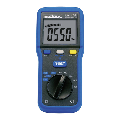
Themeteralso hasamanualrangemode.Inmanualrange, youselectand
lock the meter in a range. To manually select a range:
Press [RANGE] button to hold the selected range. The symbol is
displayed. Subsequently pressing the [RANGE ] button will select each
range in sequence from the lowest to highest range. Hold the button for 2
seconds to return to the Autorange Mode.
Mode Switch ( ), (W)
Press this switch to toggle between DC and AC in the voltage measure-
ments. Press this switch to toggle between the W/continuity/diode modes,
if the function switch is set to Wposition.
Back-Light and Data-Hold Switch ( >2sec),( H):
PressthisbuttonbrieflytoactivateDATA-HOLDmode.The Hannunciator
is displayed.
Press this button for two seconds to turn the Back-Light on. As this also
activates the DATA-HOLD mode, briefly press the button to return to
normaldisplay.To turnthe Back-Lightoffpress againfor twoseconds.The
Back-Light will switch-off automatically after about 30 seconds.
Auto Power-Down Mode:
If unused for about 10 minutes, the tester will power-down automatically.
Press any of the three button switches to resume power-on mode.
Voltage Measurements
1. Connect a red test probe to the "VW" jack and the black test lead to the
"COM" jack.
2.SettheFunctionswitchtothedesiredvoltageandpressthemodeswitch
to select DC or AC.
3. Touch the probes to the test points, the range will change automatically
to the level that will display the input voltage with best resolution.
4. The value indicated in the display window is the measured value of
voltage with proper decimal point and annunciator indication.
5. For dc, a (-) sign is displayed for negative polarity; positive polarity is
implied.
Resistance Measurements
1. Set the Function switch to the " W" position.
2. Turn off power to the circuit under test. External voltage across the
components causes invalid readings.
3. Connect a red test probe to the "VW" jack and the black test lead to the
"COM" jack.
4. Connect the test leads to the measurement points and read the value
from the display.
Testing Diodes
1. Set the Function switch to Wposition.
2. Turn off power to the circuit under test. External voltage across the
components causes invalid readings.
3. To toggle between the W/continity/diode modes, press Mode Switch.
4. Touch probes to the diode. A forward-voltage drop is about 0.6V (typical
for a silicon diode).
5. Reverse probes. If the diode is good, "OL" is displayed. If the diode is
shorted, a value near 0mV will be displayed.
6. If the diode is open, "OL" is displayed in both directions.
Continuity Measurements
1. Set the Function switch to Wposition.
2. Turn off power to the circuit under test. External voltage across the
components causes invalid readings.
3. To toggle between the W/continity/diode modes, press Mode Switch.
4. Connect the test leads to the two points at which continuity is to be
tested. The buzzer will sound if the resistance is less than approxi-
mately 20W±5W.
MAINTENANCE
Battery Replacement
Power is supplied by four 1.5V (AAA size) batteries. The " " appears on
the LCD display when replacement is needed.To replace the batteries,
remove the screw from the back of the meter and lift off the battery cover
case. Remove the batteries from battery contacts.
Cleaning
Periodically wipe the case with a damp cloth and detergent, do not use
abrasives or solvents.
WARNING
Remove test leads before changing batteries
or performing any servicing.
METRIX ELECTRONICS LTD
Minchens Court, Michens Lane, Bramley
Tadley, Hampshire, RG26 5BH, U.K.
Tel: +44 (0)845 0343234 Fax: +44 (0)845 0343233
DEC. 04
