MKS SM1690 Series Specification sheet

SM1690T for line 3 x 400V
SM1690U for line 3 x 480V
SWITCHING POWER GENERATOR
WITH EMBEDDED MICROCONTROLLER
FOR 10 KW MAGNETRON H 0915
TECHNICAL NOTE
(issue December 2013)
SM 1690

SM 1690 SM 1280
SM 1690
File: SM1690_r5eng - Dec. 2013 - Technical note: SM1690 page 1 of 18
(Cover Rear)

SM 1690 SM 1280
SM 1690
File: SM1690_r5eng - Dec. 2013 - Technical note: SM1690 page 1 of 18
CE Declaration of Conformity
Dichiarazione di Conformità CE
Manufacturer’s Name: ALTER s.r.l
Nome del Costruttore:
Manufacturer’s Address: Via Curie, 8 - 42122 Reggio Emilia - Italy
Indirizzo del Costruttore:
Declare that the microwave generator:
Dichiara che il Prodotto:
product name: SM1690 (power supply) and TM100 (microwave generator head)
nome del prodotto SM1690 (alimentatore elettrico) e TM100 (generatore a distanza)
model: SM1690T.xxx, SM1690U.xxx, TM100.xxx
modello
The product described above is in conformity with the provision of the following European Directives:
Il prodotto sopra descritto è in conformità con le seguenti Direttive Europee:
2006/95/CE Harmonization of the laws of the member States relating to electrical equipment designed for use within
certain voltage limits
Riavvicinamento delle legislazioni degli Stati membri relative al materiale elettrico destinato ad essere
adoperato entro taluni limiti di tensione
2004/108/CE Harmonization of the laws of the member States relating to electromagnetic compatibility
Riavvicinamento delle legislazioni degli Stati membri relative alla compatibilità elettromagnetica
Conformity to the Directives is assured through the application of the following standards:
La conformità alle Direttve è assicurata tramite l’applicazione dei seguenti standards:
Reference number Edition Description
Numero di riferim Edizione Descrizione
EN61010-1 2011-03 Safety requirements for electrical equipment for measurement, control and laboratory use
Prescrizioni di sicurezza per apparecchi elettrici di misura, controllo e per uso in laboratorio
EN61000-6-4 2007-11 Electromagnetic compatibility - Generic emission standard, industrial environment
Compatibilità elettromagnetica - Norma generica sull’ emissione, ambiente industriale
EN61000-6-2 2006-10 Electromagnetic compatibility - Generic immunity standard, industrial environment
Compatibilità elettromagnetica - Norma generica sull’ immunità, ambiente industriale
Reggio Emilia, December 2013. Marco Garuti
General Manager

SM 1690
page 2 of 18 File: SM1690_r5eng - Dec. 2013 - Technical note: SM1690
SM 1690 SM 1280
SM 1690
File: SM1690_r5eng - Dec. 2013 - Technical note: SM1690 page 3 of 18
Alter’ policy about Reduction on Hazardous Substances (RoHS) and Waste Electrical and Electronic
Equipment (WEEE)
Law Reference
• Directive 2002/96/EC of European Parliament (WEEE)
• Directive 2002/95/EC of European Parliament (RoHS)
• Decreto Legislativo D.L. n. 151 – 25/07/2005 (WEEE and RoHS)
At the present date 99% of components in our stock is RoHS compliant.
The components still not compliant are hold in stock and still used because there is not the same or equivalent product RoHS
compliant, or because the product is a spare part for equipment produced and put on market before 1st July 2006.
Alter Risk Assessment on RoHS
Of the six substances forbidden from electronic equipment (Lead (Pb), Mercury (Hg), Cadmium (Cd), Hexavalent Cromium
(Cr-VI), Polybrominated biphenyls (PBB), Polybrominated diphenyl ethers (PBDE)) only two are used in Alter’s current
manufacturing process, Pb and Cr-VI, of whose lead is the more important.
Cr-VI: No more used. May be present within the limit of 0,1% in weight as set by Directive.
Lead: We are already using alternative alloys lead-free, but as we still have components that cannot be soldered
without lead, we have to use some lead-alloy for welding. We are putting any effort on reducing lead weight
within 0,1% of products as set by Directive.
Important information to User about disposal, recycling, reuse of this electronic equipment at the end of its
useful life (WEEE Directive).
According to Annex IA and IB of EC Directive 200/96/EC this equipment is not included on the list of categories/products
covered by the Directive (as a matter of fact it does not perform a function alone, must be included into a larger process equipment
and it’s for stationary use).
Nevertheless we invite the User to respect the following Directive rules:
• this WEEE is not a municipal waste and should be collected separately according to rules of your country
• the symbol means that this WEEE cannot be disposal in the same place and in the same way like municipal waste
• this WEEE may present risk for environment as well as for person in case of disposal in unauthorized place, due to content
of hazardous substances
• for disposal of this WEEE in unauthorized area the User may be charged with a fine or prosecuted by law.
Rev. Revision note Date File
0 First emission January 2009 SM1690_r0
1 Index and connectors corrections March 2009 SM1690_r1
2 Upgraded norm references and drawings June 2010 SM1690_r2
3 Corrections to the text October 2010 SM1690_r3
4 Added “U” version data June 2011 SM1690_r4
5 Updates of norms and logo December 2013 SM1690_r5

SM 1690
page 2 of 18 File: SM1690_r5eng - Dec. 2013 - Technical note: SM1690
SM 1690 SM 1280
SM 1690
File: SM1690_r5eng - Dec. 2013 - Technical note: SM1690 page 3 of 18
Contents
A
Alarm troubleshooting 16, 17
B
Bit alarm table 13
C
CE Declaration 1
Cleaning 6
Components layout 14
Components List 15
Conn.# 1 wiring 11
Conn.# 3, 4, 5 wiring 12
Conn.# 6 wiring 13
E
Environmental conditions 6
Equipment installation 7
Equipment ratings 5
F
Firmware upgrade 9
Fuses replacement 6
Fuses specifications 6
G
General description 4
General information 3
H
Handling instructions 7
Handling warnings 4
How to order 18
I
Internal settings 10
M
Meaning of external command 9
Monitor signals 13
P
Physical characteristics 6
Power-up procedure 8
R
RoHS conformity 2
RS232 connector wiring 11
T
Technical assistance 18
W
Warnings 3
Wiring instructions 7
Working modes 8
General Informations
This equipment satisfy the European Standard EN 61010-1
With reference to EN 61010-1 standard, note:
this appliance must be installed and serviced only by qualified
personnel.
The appliance must only be used by persons acquainted with
the regulations covering the application.
The equipment described in this manual has been classified
as industrial, scientific and medical (ISM) radio-frequency
equipments and the related standard for the Electromagnetic
disturbance is the EN55011 (Industrial scientific and medical
(ISM) radio-frequency equipment - Electromagnetic distur-
bance characteristics - Limits and methods of measurement.)
With reference to Basic Standard EN55011, this equipment
is included into Group 2 (Microwave generators, Thyristor
command equipment, Welding equipment, Induction heating
equipment or machine, Microwave industrial oven, etc.), Class
A (industrial environment): for this reason this equipment shall
not be used in the residential, commercial and light-industrial
environment.
The SM1690x and TM100, when properly installed, complies
with the limits of radio disturbance characteristic of a Group2,
Class A equipments as stated by EN55011.
A copy of the tests performed may be sent on request. Note
that these tests cannot be used as a conformity certificate of the
user’s final equipment.
WARNINGS
The SM1690 is powered by industrial main line and has
high voltage output (close 8 kV): read carefully this manual
before using. Be sure of correct connections and use.
Failure to comply with the instructions enclosed in this
manual may involve considerable risks for the staff respon-
sible for checking and using the equipment, as well as the
risk of general malfunctions of the equipment itself.

SM 1690
page 4 of 18 File: SM1690_r5eng - Dec. 2013 - Technical note: SM1690
SM 1690 SM 1280
SM 1690
File: SM1690_r5eng - Dec. 2013 - Technical note: SM1690 page 5 of 18
Handling Warnings
The SM1690x has two handles on the front panel to help
unpacking and handling operations: never use only the
handles to lift the equipment but support the weight with
an appropriate base on bottom!
The handles do not withstand the off-center weight of the
equipment (40 kg = 88 lbs).
General Description
The SM1690x is able to supply the power required by a
magnetron type H0915 (Hitachi), with nominal power of 10
kW @ 2.45 GHz.
The output power can be adjusted continuously, from 10% up
to 100%, using an external analog signal from 1 to 10Vdc,
or through fieldbus interface.
The standard model does not have any local command, but has
the fieldbus interface.
The unit, in addition to power the magnetron, has several
features and commands to control and power the magnetron’s
accessories.
The SM1690x has been developed to power and monitor our
remotable microwave head type TM100.
The SM1690x unit may be used also to power microwave
generators (heads) developed by others manufacturers under
condition that they are electrically compatible: moreover it is
mandatory to use our filament transformer FIL250 to gua-
rantee a proper filament reduction curve. See the electrical
specifications of the unit on the next pages.
The user must provide a proper cooling flow: the cooling air
enter into the unit from the front side, it passes through the
internal circuits and components, then it goes out from the
back. The intake air flow is approx. 200 m3/h.
The SM1690 is available for European voltage 3 x 400V and is
offered, as standard, with fieldbus interface like:
- CANopen or
- Modbus/TCP or
- Profibus,
allowing connection of multiple devices on the same bus.
See the final chapater “How to order” for more details and p/n.
The front panel includes 5 status LEDs:
POWER ON (GREEN): ON when power is present
INTERLOCK ON (WHITE): ON when Interlock chain
is closed (=OK)
READY (YELLOW): ON when filament is ready
(Preheating timer is elapsed)
Flashing during preheating
time
MICROWAVE ON (BLUE): ON when microwave is
emitted (Enabling command
is ON)
ALARM (RED): ON when an alarm state is
present.
The rear panel comprises the following (see next drawing):
1) 7 pins socket for main supply (CONN #1) [male]
2) 14 pins socket for mw head signals (CONN #4) [female]
3) socket for the high voltage output (CONN #5) [female]
4) 7 pins socket to power microwave head (CONN #3)[female]
5) 25 pins “D” type socket for I/O signals (CONN #6) [female]
6) RJ 45 on ETHERNET-MODBUS TCP interface, 9 pins “D”
type socket for CANOPEN/PROFIBUS interface
7) 9 pins “D” type socket for RS232 port [female]
8) fuse holders (F1, F2), screw type
10) equipment label
11) BUS address switch
FRONT PANEL
WARNING!
REFER SERVICE TO QUALIFIED
PERSONNEL ONLY.
MAY PRESENT RISK OF
ELECTRICAL SHOCK INSIDE!
ACHTUNG!
NUR FACHKRAFTE DIE WARTUNG
MACHEN MUSSEN
MAN SICH EINEN SCHLOG HOLEN!
ATTENZIONE!
LA MANUTENZIONE DEVE ESSERE
FATTA DA PERSONALE QUALIFICATO.
RISCHIO DI SCARICHE ELETTRICHE
ALL’INTERNO!
COLLEGARE ALLA TERRA
DEL GENERATORE REMOTO
VERBINDER DIRECT MIT DER
ERDUNG DES MIKROWELLEN GENERATOR
CONNECT DIRECTLY TO GROUND
OF MICROWAVE HEAD
1
2
3
4
5
6
7
8
9
0
1
2
3
4
5
6
7
8
9
0
BUS ADDRESS
CONN #6
CONN #4
CONN #3
CONN #1
CONN #8
CONN #2
CONN #7
F1 F2
ATTENZIONE!
USCITAALTA TENSIONE
WARNING!
HIGH VOLTAGE OUTPUT
WARNUNG!
HOCHSPANNUNGSAUSGANG
CONN #5
RS 232
46PP01280
1
2
4
8
3
6
75 11
CURRENT
DATES/N
POWER
INPUT FREQ.
REGGIO E. - ITALY
MODEL P/N
ar
e
t
l
KVA
V
A
Hz
10
REAR PANEL

SM 1690
page 4 of 18 File: SM1690_r5eng - Dec. 2013 - Technical note: SM1690
SM 1690 SM 1280
SM 1690
File: SM1690_r5eng - Dec. 2013 - Technical note: SM1690 page 5 of 18
SM 1690 Ratings & Specifications
Description Units Value Function Note
SM1280T: Line input nominal:
Working voltage range
Max Absolute voltage:
Input Current, max:
Vac
Vac
Vac
Arms
3x400
360÷440
450
26
Power input, 3 phase + GND
@400V input, full power
CONN #1, pin 2-3-7
See wiring schematic
SM1280U: Line input nominal:
Working voltage range
Max Absolute voltage:
Input Current, max:
Vac
Vac
Vac
Arms
3x480
390÷570
600
22
Power input, 3 phase + GND
@480V input, full power
CONN #1, pin 2-3-7
See wiring schematic
Transient Overvoltage Cat. II According IEC 664
Output power, max Wdc 14000 Electrical power to magnetron input
Electrical efficiency (Out/In) 92% Max heat to dissipate ~ 1100 W
Output current range: mA 160÷1600 Adjustable range 10÷100%
Output current max: mA 1600 Limit in Power Control Mode With max amb temp. 40°C
Output voltage, max: Vdc 8800 Characteristic of magnetron Range 8.6÷9.1 kV
Output ripple, max ±4.5%@ 300 Hz
±3% @ 40 kHz
Ripple in current at max power
Output linearity: Wdc ±20 Corresponding to ~ 15 Wrf
Output stability: 1% For input fluctuations within ±10%
Filament pre-heating time sec 150 Preheat filament at Power
ON or after Hibernate is OFF
When done, READY signal is ON
Magnetron power:
[Frequency]
kW
MHz
10
[2460 ]
H0915 Use our TM100 Head
Enabling signal, digital input: Vdc +24
Range 5÷30
ON/OFF output & alarm reset
Input Z: 4k7 kOhm
CONN #6, pin 4. To reset alarm hold
OFF for 2 seconds
Response time to full power: msec 80 Linear time Using Enabling signal
Response time to switch OFF: msec 20 Using Enabling signal
Pulsability of output, min TON msec 100 Max power 10 kW, Freq= 5Hz Using Enabling signal
Switch OFF time for alarm msec 3 Automatic shut-off
Reference signal, analog input: Vdc 1÷10 Power control 10÷100% CONN #6, pin 5. Ground pin 18.
Input Z=50 kOhm, optoinsulated
Alarm contact, general:
Contact rating: max voltage
max current:
V
mA
30
500
OPEN: Alarm state or power
OFF
CLOSED: OK
CONN #6, pin 1-14
Alarm code, 4 bit contacts (0/1)
Contact rating: max voltage
max current
V
mA
30
100
Inform type of alarm with
emission of 4 bit code
See relevant table
CONN #6, pin 8-21-9-22 (bit 0...3)
Common pin 13
Ready contact:
Contact rating: max voltage
max current
V
mA
30
500
CLOSED when filament is
pre-heated & ready
OPEN not ready filament or
Alarm state
CONN #6, pin 12-24
Hibernate signal, digital input: Vdc +24
Range 5÷30
ON filament is hibernate.
OFF or not used:filament heated
CONN #6, pin 11
Z= 4k7 kOhm
Interlock contact: OPEN: Alarm, shut OFF
outputs. CLOSED: OK
CONN #6, pin 10-23
Monitor signals, analog outputs (2): Vdc 0÷10 Monitors various parameters
Max current: 10 mA
See relevant schematic
CONN #6, pin 2-15 (1); pin 3-16 (2)
Designed for receiver impedance
>30 kOhm (for accuracy <1%)
Voltage output (internal generator) Vdc +24÷30 Auxiliary voltage genera-
tor, unregulated, for user
interface
CONN #6, pin 10, 20. Max current:
100 mA

SM 1690
page 6 of 18 File: SM1690_r5eng - Dec. 2013 - Technical note: SM1690
SM 1690 SM 1280
SM 1690
File: SM1690_r5eng - Dec. 2013 - Technical note: SM1690 page 7 of 18
Fuses specifications
The SM1690x has 2 fuses installed on the rear panel (look at
the drawing on page 4, pos. 8): both fuses, labelled F1 and
F2, protect the output line powering the remote head.
A third fuse is on the main board M416, to protect internal
control circuitry.
Fuse F1 and F2 specs:
- Size, type: 10x38 mm, ceramic cartridge
- Speed action: quick (F)
- Rated current: 6 A
- Rated voltage: 500 V
Fuse F1 specs on M416 board:
- Size, type: 5x20 mm
- Speed action: slow (T)
- Rated current: 3.15A
- Rated voltage: 250 V
Fuses replacement
To replace the fuses on rear panel proceed as follow:
- switch-off the unit, removing main line from the equip-
ment;
- unscrew fuseholder cap;
- replace the fuse with a new one with the same electrical
characteristics;
- inspect also the fuseholder: if it’s oxidated or it has burned
point then replace it;
- install the fuseholder cap and screw tight.
Internal fuse:
- switch-off the unit, removing main line from the equipment
- remove the unit cover, unscrewing the 6 screws on sides
- locate the fuseholder on M416 pcb: push the cap then rotate
it without any tool (gently!), pull up the cap and inspect the
fuse;
- replace the fuse with a new one with the same electrical
characteristics
- install the fuseholder cap: push it then rotate.
- reassemble the unit cover, screwing the 6 screws on sides
Equipment maintenance
Cleaning
Cleaning of air inlet: verify once a month. In case you need
to remove dust then proceed as follow:
- remove main line from the unit
- remove the cover
- use pressurized air from inside to outside for short time: do
not exceed or you may damage the fan
- install the cover and then power-on again.
Environmental & Physical Characteristics:
Use: Indoor use only, within industrial
enclosure
Working temperature range 5÷40°C [41÷104°F], Min-Max
ambient temperature
Altitude design criteria: for altitude up to 2.000 m
Working Humidity range 80% RH up to 31°C [88°F],
decreasing linearly to 50% RH
at 40°C [104°F]
Air cooling requirement, flow: m3/h 200 Input from front panel.
Air clean from dust
Pollution degree: 2, complies with IEC 664
Total Weigth: kg 40 [88 lbs).
Rack Dimensions, Panel Width:
Panel Heigth:
Length (Depth):
mm 480 [19”]
mm 310 [12.2 “ - 7HE/U]
mm 482 [19” ]

SM 1690
page 6 of 18 File: SM1690_r5eng - Dec. 2013 - Technical note: SM1690
SM 1690 SM 1280
SM 1690
File: SM1690_r5eng - Dec. 2013 - Technical note: SM1690 page 7 of 18
Equipment installation
The SM1690x cannot operate on a bench: it must be installed
into a proper cabinet like a commercial 19” standard enclo-
sure.
The equipment is intended for industrial use only, not for
laboratory use, and user must respect the wiring norms and
prescriptions as described into next paragraph (“Wiring
instruction”).
The equipment cannot operate cantilevered, it must be safely
fixed inside a cabinet by means of screws on the front panel
(which is provided with 4 holes) and supported by means of a
proper frame on the bottom for, at least, 3/4 of the total depth.
Usually two “L” shaped supports on each side of the equip-
ment, having a dimension of mm 10(h) x 30(l) x 2 (thick) are
suitable for that purpose.
The rear side of the equipment must be protected by a fixed
panel which can be removed only by means of tools or by a
door with security micro-switch: when the door is opened the
micro-switch must shut-off the main line. This safety precau-
tions must be taken to avoid operations on rear fuses or on
connectors while the unit is still powered.
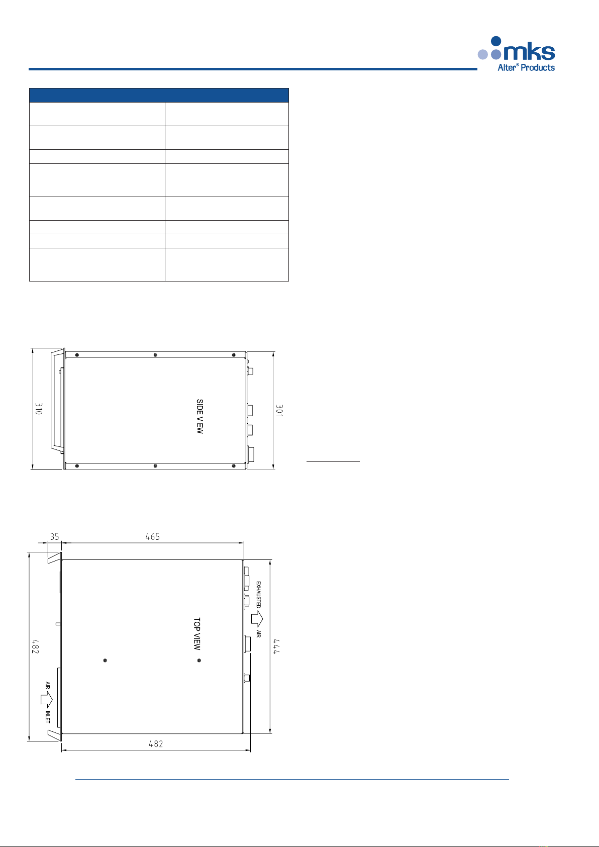
Special attention must be taken on designing the cooling air
flow in case of stacking several units into the same cabinet.
Note that each equipment has its own fan which intake approx
200 m³/h: the outlet of the exhaust air is on rear panel, the
inlets on the right side (looking at front).
When designing a board to house several units we recommend
to adopt the following design criteria:
1. use a standard 19” wide enclosure with a depth of 800 mm
(32”);
2. allow free intake of the cooling air from the front of the
cabinet and exhaust air from back panel throu the top of the
cabinet or the back side;
3. in case of ambient air with high degree of dust and moisture,
install a proper air conditioner; if you cannot do this, then you
have to use suitable air filters and instruct the user about their
cleaning;
4. provide a separation between the air intake duct and the air
outlets, in order to avoid air-recyrculating;
Handling instructions
The equipment weight is 40 kg (88 lbs). Always lift from the
bottom and use an adeguate rugged support to avoid personal
injury and damage to equipment itself.
In case of shipping, package with the original package or use
a wooden case and a proper filler: movement of the equipment
inside the package must be avoided.
Warning for handling: use handles only for help during
installation. Never use handles to lift the rack: the handles
don’t withstand the off-center weight of the rack!
To lift always lean the rack over a proper supporting base.
Wiring instructions
The SM1690x must be installed and serviced only by quali-
fied personnel acquainted with the regulations covering the
application. For safety operations the following rules must be
adopted:
I) The equipment must be grounded through the connector
#1 using pin 4 (see the wiring diagram at page 13).
II) Connect the ground screw on panel rear (indicated by
“ground” symbol) directly to the remote microwave generator
head by a separate yellow/green wire gauge 2.5 mm².
III) The main supply must be provided through connector
#1: connect phases according to schematic at page 11, the
connector’s pins can house wires with gauge up to 10 mm².
Warning: this connector is not intended for live insertion
of the unit: an external tripolar breaker must always
be provided, and the unit must be switched off before
inserting/unplugging of the connector.
IV) The connector #4, with 14 pins, brings the head’s signals
to the equipment. Use wires with max gauge of 1.5 mm²,
refer to wiring diagram at page 12.
V) The connector #5 is the high voltage output and must be
connected to magnetron’s cathode, usually marked with the
symbol “FA” on the magnetron’s teminal. The voltage value
is near -9 kV .Use a proper insulated cable with working vol-
tage >10 kVdc and minimum gauge of 0.25 mm²; protect the
wire with sheating (armoured if appropriate).
Assemble the wire into plug according to professional rules.
The reliability of the equipment starts from the h.v. connec-
tions.
ALTER may supply the HV cable with lenght on request.
VI) The connector #3 provides the power supply for the
filament transformer (usually located near the magnetron), the
magnetron fan and a warning lamp. Use wires wih max gauge
1.5 mm². Refer to wiring diagram at page 12;
VII) The “D” type female connector #6 has 25 pins and brings
the I/O signals to the equipment. Refer to wiring diagram at
page 13.
VIII) The CONN# 8 has a type of socket that depends on the
fieldbus interface:
- RJ 45 on Ethernet-Modbus TCP
- 9 pin “D” on CANopen/Profibus
IX) The “D” type female connector RS232 has 9 pins and it’s
a standard serial port, that can be used to upgrade of the sof-
tware from a PC, or to retrive internal data through FrontPa-
nel GUI. Look the pin-out at page 11.
X) The user must provide external cut-off device, to protect
the SM1690x from short-citcuit and thermal runaway; this
external protection device must also allow to switch-off the
main line for maintenance operations.
XI) The external circuit breaker must be a 3-poles current
limiter breaker and must comply the norm EN61010-1.
XII) The external circuit breaker must be in close proximity
of the equipment and within easy reach of the operator.

SM 1690
page 8 of 18 File: SM1690_r5eng - Dec. 2013 - Technical note: SM1690
SM 1690 SM 1280
SM 1690
File: SM1690_r5eng - Dec. 2013 - Technical note: SM1690 page 9 of 18
XIII) The external circuit breaker must be marked as the
disconnecting device for the SM1690x.
XIV) The connector #1 must never be used as a switch-off
device.
Failure to comply with these instructions may involve
considerable risks for the staff responsible for checking and
using the equipment, as well as the risk of general malfunc-
tions of the equipment itself.
Equipment operation
Power-up procedure
Before powering-up the equipment, double check to have pro-
perly connected it, (look at the chapter “Wiring Instruction”)
then power on the unit through your external contactor.
Once switched OFF wait at least five seconds before setting it
ON again. The OFF state, between two consecutive ON state,
must last five seconds minimum.
With psu having network capability, like CANOpen (p/n
ending xxxCAN) or Modbus/TCP (p/n .....MTCP) or Profibus
(p/n......PROF) it’s mandatory to provide the physical signals
of “Power Enable” and “Interlock” (see the schematic of the
signals connector on next pages) otherwise the unit will not
respond to any bus command.
For protocol explanation refer to relevant Application Note.
The working status for these versions is the same of other
version (read the chapter “Working Modes”): the status is then
provided through messages sent on the bus.
At power on the unit enters into a “BOOTLOADER” state for
few seconds to allow firmware upgrade, then it goes imme-
diately into “STAND-BY” and here waits until the “filament
heating” is completed. If the unit is remotely driven, it is
necessary to remove the default Hibernate command, that
prevents the hardware from heating the filament.
If any alarm is present, the units stops, and the filament is off.
At the end of the heating cycle the unit enters in “READY”
mode: the power supply may power the magnetron, which
generates microwave, only when it will receive the enabling
command.
Any type of alarm forces the unit to exit from thr “READY”
state and enters it in “ALARM” state.
In absence of alarms the power supply may be left in “Ready”
continuously: when it receives the enabling command (ON) it
enters into “RF-ON” state and generates output power, when
the enabling command is removed (OFF) the unit comes back
to “READY” state.
Working Modes
The behaviour of the SM1690x depends on its “working
status”: it has several statuses with different meaning and
functionality. The logic flow of these statuses is showed on the
previous drawing. These statuses are:
BOOTLOADER: it goes in this mode at power-on, waits for any
serial firmware update data, and after a few seconds, the unit
enters in Stand-By mode.
STAND-BY: it’s a waiting state, the unit is powered but not ready
as the magnetron filament is not powered; all the working
parameters can be setted from Operator Panel; the unit enters
in Stand-By from the previous Bootloader state or when an
alarm, or hibernate condition is true.
The unit exits from Stand-by and goes to Preheating only
if there aren’t alarms, the Interlock chain is closed and the
HIBERNATE command is OFF.
PREHEATING: it’s a temporary state, driven by a timer, to allow
the filament to be heated. The unit enters in this mode after a
remote command or automatically after the end of Bootloader
state. When the timer is elapsed the unit goes in Ready mode.
READY: it’s a waiting state. The unit waits the enabling com-
mand to generate power to the magnetron. The magnetron
filament has been, and is properly heated.
The unit may last in this state as long as needed: it exits auto-
matically in case of alarm or when the ”Hibernate” command
is asserted. It goes to next “MW-ON” status when the enabling
command is set ON.
STANDBY
PREH
RUN
READY
HIBERNATE=0 &
INTERLOCK=1 &
ALARM=0
HIBERNATE=1 or
INTERLOCK=0 or
ALARM=1
HIBERNATE=0 &
INTERLOCK=1 &
ALARM,=0 &
TIME<15s
HIBERNATE=1 or
INTERLOCK=0 or
ALARM=1
HIBERNATE=0 &
INTERLOCK=1 &
ALARM,=0 &
TIME>15s
HIBERNATE=0 &
INTERLOCK=1 &
ALARM,=0 &
ENABLE=1
HIBERNATE=0 &
INTERLOCK=1 &
ALARM,=0 &
TIME>15s &
ENABLE=0
HIBERNATE=0 &
INTERLOCK=1 &
ALARM,=0 &
ENABLE=0
HIBERNATE=1 or
INTERLOCK=0 or
ALARM=1
HIBERNATE=0 &
INTERLOCK=1 &
ALARM,=0 &
ENABLE=1
BOOT
LOADER
TIME>2S

SM 1690
page 8 of 18 File: SM1690_r5eng - Dec. 2013 - Technical note: SM1690
SM 1690 SM 1280
SM 1690
File: SM1690_r5eng - Dec. 2013 - Technical note: SM1690 page 9 of 18
MW-ON: starts microwave emission at the presetted power level
while the led “MW ON” is lighted up.
The unit exits from this mode in case of:
* the enabling command is set OFF: enters into Ready state, or
* ALARM presence: the unit goes to Stand-by, or
* the INTERLOCK chain is open: it goes to Stand-by again.
* the Hibernate command is set to ON: jump to Stand-by.
Meaning of external commands.
HIBERNATE: has value ON/OFF. If ON the magnetron’s
filament is not powered and the SM1690x goes into Stand-by
mode.
In OFF the unit makes filament heating and, when the related
timer is elapsed, enters in Ready mode.
If a user don’t like to use the Hibernate function, he may not
connect the HIBERNATE control signal: the system then
detect it as in OFF condition.
POWER ENABLE: has value ON/OFF, but its effect is related
also with the Hibernate command as follow:
a) in OFF state - and HIBERNATE is OFF - the unit performs
filament preheating and goes in Ready mode but does not
generate output power, even if the reference signal is >0;
b) in OFF state - and HIBERNATE is ON - the unit is in
Stand-by mode but does not generate output power, even if the
reference signal is >0;
c) in ON state - and HIBERNATE is OFF - the unit waits the
end of preheating timer, if not yet elapsed, then starts to gene-
rate output power;
d) in ON state - and HIBERNATE is ON - the unit is in Stand-
by mode but does not generate output power, even if the
reference signal is >0.
POWER SET: it’s an analog input value and has the meaning
of “desired percent” of the full output power (14000W)
When this value is lower than 1Vdc the unit does not gene-
rate any output power, when >1Vdc the unit generates power
proportional to this signal value.
The CPU drives the unit to obtain an electrical output power
(Va * Ia) value proportional in a linear way to the reference
input signal. The scaling is 1400W/V.
INTERLOCK: it is an external hardware chain of contacts,
that must be closed all at the time to have the internal relay
closed. (ON condition). When in ON the CPU light-up the
related Interlock OK led; in OFF state the led is Off and the
unit goes in Stand-by, as all dangerous voltages on the head
connector are off.
Firmware upgrade
The software stored on the CPU (firmware, on a flash
memory) can be upgraded to a newer version using the RS232
serial port on the unit, connected to a PC.
Important remark: at power-on, even if a program is already
stored, the microprocessor enters a “BOOTLOADER” status,
lasting 2 seconds, during which it is possible to overwrite,
through the serial RS232 port, the stored code.
If no new code is loaded within 2 seconds, the previously stored
one is run.
To upload a new program through the bootloader, simply
connect the SM1690x serial port to the PC serial port, using a 9
pin 1:1 cable (only TX, RX and Ground are used, but also a full
cable will fit. See schematic on page 11)
No external switch must be operated, and the unit does not start
until the new program is stored, but be sure no enable signal is
active when upgrading.
The upgrade of the firmware embedded in the SM1690x is
released as a .zip archive named “program_name.zip”.
Unpacking the .zip archive you generate:
- a directory named “program_name” containing the micro
code to be loaded,
- an executable program named “SendApplicationProgram.bat
”- the loader “sRecLoad.exe”,
- and the library “Nican.dll”.
Once unpacked the .zip program:
- enter in the folder “program_name”,
- switch-on the SM1690x
- run whithin 2 seconds the program “SendApplicationProgra-
m.bat” (which launches sRecLoad.exe application)
(This is the maximum time that the microprocessor bootloader
waits for new code to be loaded).
During the bootloader wait time, the red ALARM led is on: if
no code is sent, then the previous code is executed, and it is not
possible to change it without switching the unit off.
In case the program sRecLoad.exe sends data whithin 2
seconds, the microprocessor bootloader stores the new data
on the internal flash memory, installing the new release, and
automatically executes it when the download is done.

SM 1690
page 10 of 18 File: SM1690_r5eng - Dec. 2013 - Technical note: SM1690
SM 1690 SM 1280
SM 1690
File: SM1690_r5eng - Dec. 2013 - Technical note: SM1690 page 11 of 18
Internal settings
The SM1690x comes in the default settings with all
the SW1 switches= OFF and switch 3 of SW2= OFF:
nevertheless some working parameters can be modifyed
using internal dip-switches.
DIP-SWITCH #1 (on board M416.x: see position on next
page): allows to override some external alarms, as follow
SW1-1 if set to ON disables ARC DETECTOR alarm.
SW1-2 if set to ON disables MAGNETRON THERMAL
alarm
SW1-3 if set to ON disables AIR FLOW alarm
SW1-4 if set to ON disables WATER FLOW alarm
SW1-5 if set to ON disables HEAD ENABLE
SW1-6 if set to ON disables microswitch CARTER alarm
SW1-7 if set to ON inhibits the automatic opening of the
interlock relay from the CPU in case of alarm. If it is ON,
only the opening of the MICRO CARTER switch can de-
energize
the interlock relay, cutting in this way the head supply and
leaving the head in a safe condition.
SW1-8 – not used.
DIP-SWITCH #2 (on board M416.x)
SW2-1: not used
SW2-2: not used
SW2-3 if set to OFF enables the external control of the
unit, set to ON enables the fieldbus control.
The default setting for SM1690x is OFF.
WARNING: in ON state, if no fieldbus interface is
present or if no communication is present on the bus,
an alarm is generated.
SW2-4 must be set to OFF for normal
operation, if set to ON enables the
hardware test of the M416 board.
WARNING:
don’t enable
this switch: the
use is limited to
trained personal
only and for test
purposes.
CPU POWER
HEAD INTERFACE POWER
PLC INTERFACE POWERING
HEAD INTERFACE (CONN#2)
HEAD POWER OUT (CONN#4)
230Vac BOARD POWER
LED BOARD
FIELDBUS INTERFACE
RS232 INTERFACE
M416.1 CONNECTORS, TEST-POINTS, LEDS
TRIMMERS, DIP-SWITCHES, JUMPERS
DIP-SWITCH#2
DIP-SWITCH#1
FILAMENT VOLTAGE ADJ.
PTC ON HEATSINK
FAN POWER
DRIVER COMMAND
PARAMETERS SENSING
CONTROL I/O (CONN#5)
id32384187 pdfMachine by Broadgun Software - a great PDF writer! - a great PDF creator! - http://www.pdfmachine.com http://www.broadgun.com

SM 1690
page 10 of 18 File: SM1690_r5eng - Dec. 2013 - Technical note: SM1690
SM 1690 SM 1280
SM 1690
File: SM1690_r5eng - Dec. 2013 - Technical note: SM1690 page 11 of 18
Connector # 1 wiring
RS232 connector wiring
id32273156 pdfMachine by Broadgun Software - a great PDF writer! - a great PDF creator! - http://www.pdfmachine.com http://www.broadgun.com
1690T
1690

SM 1690
page 12 of 18 File: SM1690_r5eng - Dec. 2013 - Technical note: SM1690
SM 1690 SM 1280
SM 1690
File: SM1690_r5eng - Dec. 2013 - Technical note: SM1690 page 13 of 18
Connector # 3,4,5 wiring
1690
HEAD ENABLE

SM 1690
page 12 of 18 File: SM1690_r5eng - Dec. 2013 - Technical note: SM1690
SM 1690 SM 1280
SM 1690
File: SM1690_r5eng - Dec. 2013 - Technical note: SM1690 page 13 of 18
Connector # 6 wiring
MONITOR SIGNALS
valid for all versions
On the “D” type fermale connector #6, installed on the rear
panel of the PSU, there are two monitor signals, in the range
0 - 10Vdc (pin 2 and pin 3, ground on pin 15 and 16 respecti-
vely)
Forward and Reverse
Power Monitor
(if signals are availables)
Magnetron voltage
and current Monitor
(default setting)
CONN. #6
Forward Power *
10 V= 10000 W
Output Voltage Va
1 Vmon= 1000 V
Pin #2
(return pin #15)
Reverse Power *
10 V= 5000 W
Output Current Ia
1 Vmon= 200 mA
Pin #3
(return pin #16)
Description BIT 3
[22]
BIT 2
[ 9]
BIT 1
[21]
BIT 0
[ 8]
No alarm 0000
Magnetron Overtemperature 0001
Rack Overtemperature 0010
Arc Detection (on head) 0011
Overcurrent 0100
Overvoltage 0101
Air Pressure Low (on head) 0110
Water Flow Low (on head) 0111
Interlock 1000
Current Leakage on Ground 1001
Rack Alarm 1010
not implemented 1011
not implemented 1100
not implemented 1101
Communication Interrupted 1110
Bus Communication Failed 1111

SM 1690
page 14 of 18 File: SM1690_r5eng - Dec. 2013 - Technical note: SM1690
SM 1690 SM 1280
SM 1690
File: SM1690_r5eng - Dec. 2013 - Technical note: SM1690 page 15 of 18
COMPONENT LAYOUT

SM 1690
page 14 of 18 File: SM1690_r5eng - Dec. 2013 - Technical note: SM1690
SM 1690 SM 1280
SM 1690
File: SM1690_r5eng - Dec. 2013 - Technical note: SM1690 page 15 of 18
Component list (See drawing pag.14)
Pos. Q.ty Description P/N Note
1 1 CPU board M416 800000416/1690
2 1 Driver board M311 800000311/1690
3 1 Power board M409 800000409
41 Fan, 230V VE2GRE120/6221R
1 Fan capacitor 2µF CR202A450
5Not present
6 1 LED board M417 800000417
7 1 Magn. Breaker IA3RV1331/4FC10
8Not present
9 1 Main line filter FL50FCD10
10 Not present
12
1 14 pins Socket AMP/CPC MOCPC14/1826411 CONN#4
14 female pin AMP TYPE III MOCPCX/1630881 CONN#4 pins
1 14 pins Plug AMP/CPC (*) MOCPC14/1826491 PLUG#4
14 male pin AMP TYPE III (*) MOCPCX/1630861 PLUG#4 pins
13 2 Panel Fuseholder 10x38 FUP1892
2 Fuse 6A 500V 10x38mm FU10X38/6A
14 1 HV rectifier bridges pack 800000406
15 1 HV Transformer 42FT1690TD (vers. “T”) 42FT1690UA (vers. “U”)
16 1 HV feedback board M305 800000305/1280
17 1 Capacitor board M307 800000307/1690T
18 1 HV connector GES HB31 MOHB31 CONN.#5
1 HV connector Plug GES HS31 (*) MOHS31 PLUG.#5
19 Not present
20
1 7 pins Socket AMP/CPC MOCPC07/2113981 CONN#3
7 female pin AMP TYPE III MOCPCX/1630881
1 7 pins Plug AMP/CPC (*) MOCPC07/2114001 PLUG#3
4 male pin AMP TYPE III (*) MOCPCX/1630861
1 Cable clamp for 7 pin plug (*) MOCPCX/1826521
21
1 7 pins Socket AMP/CPC MOCPC07/2061371 CONN #1
4 male pin AMP TYPE XII 60A MOCPCX/1939914
1 7 pins Plug AMP/CPC (*) MOCPC07/2061361 PLUG #1
4 female pin AMP TYPE XII 60A (*) MOCPCX/1939902
1 Cable clamp for 7 pin plug (*) MOCPCX/1826521
22 1 HV inductor 42FI1690B/AT
23 1 LV inductor 42FI1690TB/BTR
24 1 Current feedback board M302 800000302/1690
25 1 Air grid 462282014
26 1 Field bus board M366 800000366
27 1 Control connector DB25 MODFL25F CONN #6
1 Control cable and header (*) PLUG #6
28 1 RS232 interface connector DB9 MODFI09F RS232
1 RS232 connection cable 1:1 (*) PLUG RS232
29 1 Node Address selection board M419 800000419
30 1 Line autotransformer 42ATT230/011
31 2 IGBT module TTSKM200/GB125
32 1 Bridge rectifier SKD6212 DDSKD6212
33 2 Handles AR366601
Note: Components marked with (*) are included in the connector set p/n 44SET1280/1690 to be ordered separately

SM 1690
page 16 of 18 File: SM1690_r5eng - Dec. 2013 - Technical note: SM1690
SM 1690 SM 1280
SM 1690
File: SM1690_r5eng - Dec. 2013 - Technical note: SM1690 page 17 of 18
ALARM TROUBLESHOOTING
Code Description Cause/Solution
01 Magnetron Over
Temperature
a) Check water flow and incoming water temperature
b) Check magnetron thermoswitch (contact grounded=OK,
open=alarm)
c) Check setting of magnetron thermocouple: if latter isn’t
present the alarm threshold must be set = 0
d) Check air flow.
e) Excess of reverse power. Reduce power,
02 Rack Over
Temperature
a) Check for restrictions to the air flow
b) Eliminate air recirculating between outlet on the sides and the
rear inlet
03 Arc Detected
Electric arc in waveguide.
If arc detector isn’t used, the related input must be grounded.
If used, contact grounded=OK, open=alarm
On alarm, check waveguide and magnetron antenna status.
Check Arc detector wiring.
04 Over Current
An excessive current has been detected, or a dangerous
temperature is present into the unit.
a) Check air flow blocks.
b) Eliminate air reflow between side entry and rear output.
c) A short circuit is present on H.V. cable: check wiring.
05 Over Voltage
a) The high voltage connection is open
b) Magnetron may be moding
c) The high voltage connectors are not fully inserted: if true
check for h.v. spot discharge inside socket/plug: in case replace
them.
d) The filament is cold: check filament current with high voltage
OFF (=enable signal OFF, h.v. connector #3 disconnected)
Check filament transformer wiring and compliance.
e) Verify preheating timer checking how many seconds require
the “READY” led to become ON stable: if you feel too short try
to enable the unit (= enable MW ON) only 10 seconds after
enabling the filament (if the command is available) or after
general power ON (when the filament command is always ON)
f) check the filament timer (with the FrontPanel program from the
PC): set >10 seconds.

SM 1690
page 16 of 18 File: SM1690_r5eng - Dec. 2013 - Technical note: SM1690
SM 1690 SM 1280
SM 1690
File: SM1690_r5eng - Dec. 2013 - Technical note: SM1690 page 17 of 18
ALARM TROUBLESHOOTING
Code Description Cause/Solution
06
Low Air
Pressure
from head
If it isn’t used the related input must be grounded.
If used, contact grounded=OK, open=alarm
Check head air filter.
07 Low Water Flow
from head
If it isn’t used the related input must be grounded.
If used, contact grounded=OK, open=alarm
Check head water flow.
08 Open Interlock Check interlocks on magnetron head assembly including
waveguide. Check 25 pin D-Sub interlock
09 Current Leakage
Check Connector # 3 for signs of arcing: in case replace both
socket & plug with new one.
Check arcing on the magnetron head.
in case replace the magnetron
10 Rack Error
The unit has detected an output current 10% lower than
expected, usually due by a sudden drop of the main line voltage:
check the main line
11 - Not implemented
12 - Not implemented
13 - Not implemented
14 Communication
interrupted
The unit was running in “remote control mode” and the
communication failed. Check:
a) cable and connectors insertion
b) remove any “suspend or low power mode” from yr PC (the OS
may stops to drive the PC serial port)
c) disable any screen saver from the PC
d) do not move the FrontPanel window on yr desktop: some
early version of operating system may stop driving the serial
port.
15 No data transfer
on fieldbus
The unit was running in “remote control mode” and the
communication failed. Check:
a) fieldbus cable and connectors
b) master device (PC or PLC) functionality.
c) correct node addressing on psu

SM 1690
page 18 of 18 File: SM1690_r5eng - Dec. 2013 - Technical note: SM1690
How to order
Power supplies: SM1690x.yyy1b, where:
x: T for 400V, U for 480V
yyy: don’t care, it’s the code
we use for customized unit;
j (version code): 1 : BUS (standard) version fol-
lowed by the type of bus
b (bus type) MTCP= Modbus-TCP
CAN= CANOpen
PROF= Profibus
I.e.: SM1690T.ALT1MTCP: input 400V, Alter brand,version
with Modbus-TCP bus interface
Alter reserves the right to improve or modify this products,
at any time, without obligation to notify any person or
entity of such changes.
No part of this publication may be reproduced without the
express written consent of Alter.
All rights reserved.
Technical Assistance:
Alter s.r.l
42122 Reggio Emilia - ITALY
Tel: ++39 0522 553 820; fax ++39 0522 553 577
Web: www.altersystem.com
This manual suits for next models
2
Table of contents
Other MKS Inverter manuals
Popular Inverter manuals by other brands

Diloc
Diloc D.IN-CONSOLE12 installation manual

REFU
REFU REFUsol 08K Installation and operating manual

Modul-System
Modul-System True Sinewave Series owner's manual

ECTIVE
ECTIVE SI Series Installation and operating instructions

Streetwize
Streetwize SWINV150 INFORMATION FOR USE

Renogy
Renogy E.FLEX 21W R-SC001 user manual