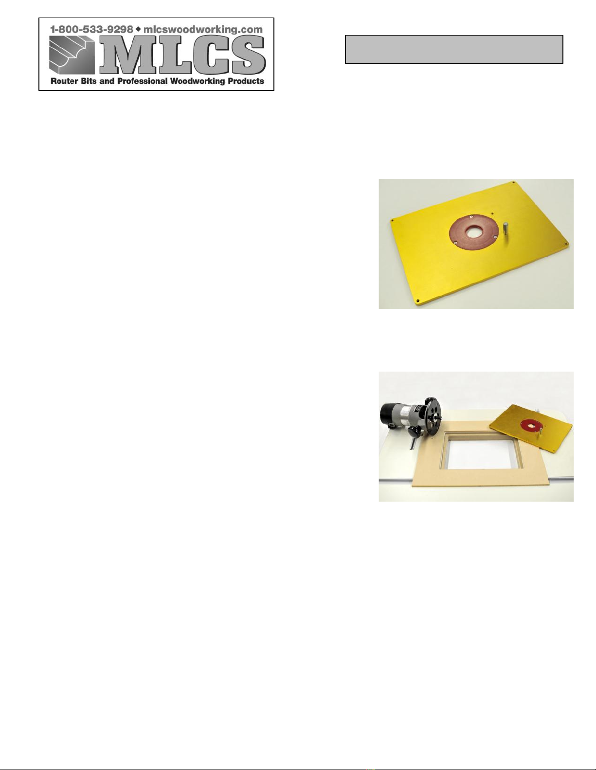
MOUNTING THE ROUTER BASE PLATE IN YOUR ROUTER
TABLE
For the MLCS 9338 all-in-one router plate see page 42.
When mounting a larger router, the handles should fit in the same
direction as the long opening. Your current router base plate will
function as the drilling jig. However, you should determine the optimum
router positioning PRIOR TO removing the base plate. Be sure to take
into account depth adjustment knobs, depth lock levers/knobs, and, of
course, the location of your switch. Place your router in the inverted
position and turned properly under the table. Then mark with tape on the
front edge of the router’s base plate to verify the position. Next, remove
the screws from the base plate.
Locate the top/front of your base plate by observing the position of the
starting pinholes. The holes will be to the RIGHT of the bit opening.
Again mark with tape front and center on the plate to serve as a reminder.
There are pre-marked mounting hole locations for the most popular
routers. Refer to the instruction sheet/legend to see if your router is
included. If it is, then drill the appropriate size hole through the insert
plate for mounting screw at the pre-marked locations. If your router is
not included in the instruction legend, then install an insert ring into the
insert plate with an opening close to the same size as the opening in your
router sub base. You will then have to align the router sub base, so that it
is centered on the insert ring. Mark the mounting hole locations on the
aluminum insert plate and drill the appropriate size hole through the
insert plate. The use of a drill press, if possible, will assure a
perpendicular through hole. You may also choose to temporarily attach
the sub base to the insert plate, using double sided tape, while you are
drilling the mounting holes through the insert plate.
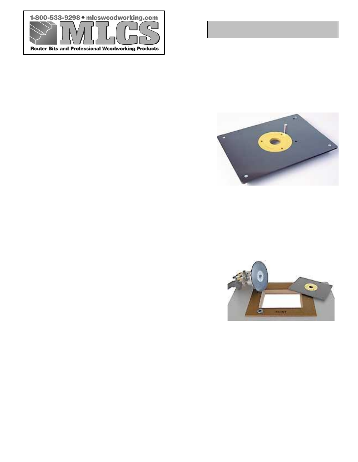
After removing the router base plate, countersink the mounting holes in
the top side of the 9334 router plate, similar to the router’s own base
plate. For best results, we recommend a single flute countersink at a
slow speed and a drill press if available.
Drill a 5/16” diameter hole and inset the magnets into your router table
top underneath where the allen head adjustment screws are located.
Finally, mount the 9334 router plate to the router. If the screws that came
with your router are not long enough, longer screws can be purchased at a
hardware store or home center in your area.
Copyright 2010 MLCS ltd. Page 43