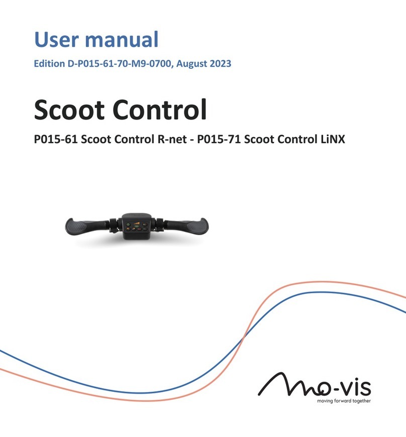
Mo-vis P015-61 User manual

moving forward together
Scoot Control
P015-61 Scoot Control R-net
Installation manual
Edition 5, July 2021

Contents
Contents About this manual .............................................................................. 4
Installation manual ................................................................... 4
mo-vis bv ................................................................................... 4
Important information ........................................................................ 5
Warranty ............................................................................................ 6
Repair and replacement ............................................................ 6
Amendments ............................................................................. 6
Disclaimer and limitations of remedies .................................... 7
Voiding of warranties ................................................................ 7
Technical support ................................................................................ 8
Warning labels .................................................................................... 9
Limited liability ................................................................................. 10
Preparations ..................................................................................... 11
Qualified service engineer ...................................................... 11
Tools ........................................................................................ 11
Installation plan ...................................................................... 12
1

Installation ....................................................................................... 13
Mounting bracket .................................................................... 13
Actuator Keypad ..................................................................... 14
Configuration .................................................................................... 17
R-net configuration ................................................................. 17
On-board configuration .......................................................... 20
Testing .............................................................................................. 26
Check the Scoot Control for intactness ................................... 26
Operational test ...................................................................... 26
Test drive ................................................................................. 29
Stop test .................................................................................. 29
First time use .................................................................................... 30
Calibration ........................................................................................ 32
Enter the on-board calibration mode ..................................... 32
Execute on-board calibration .................................................. 33
Maintenance .................................................................................... 36
Monthly inspection ................................................................. 36
Yearly inspection ..................................................................... 36
Error codes ....................................................................................... 37
Fault log ............................................................................................ 39
2

R-net trip codes ................................................................................ 42
Technical data ................................................................................... 47
Product description and code ................................................. 47
Device connectors ................................................................... 47
Specifications .......................................................................... 48
3

About this manual
Installation manual
This manual contains useful and important information about your device.
Please read it carefully before use and store safely for future reference.
Our team will be happy to answer your questions.
mo-vis bv
Biebuyckstraat 15D . 9850 Deinze . Belgium
4
4 Scoot Control Installation manual

Important information
CAUTION: Incorrect use or installation may lead to risk of injury to
the user and damage to the wheelchair or other property. In order to
reduce these risks, you should carefully read this installation manual,
paying particular attention to the safety instructions and warning texts.
NOTICE: Only install this product on a wheelchair where the wheelchair
manufacturer allows the installation of third party parts.
5
Scoot Control Installation manual 5

Warranty
mo-vis bv warrants the product to be free from defects in material and
workmanship for a period of 2 years under proper use, care and service. The
dealer should never keep mo-vis products in stock for a period more than 6
months prior to delivery to the end-user. mo-vis' warranty will never exceed a
period of 2 years and 6 months after shipment.
All warranties do not extend beyond the initial purchaser from an authorized
mo-vis dealer or mo-vis itself.
Repair and replacement
For warranty service, contact your dealer (or us if bought directly). In the
event of a defect in material or workmanship, the dealer or customer must
obtain a Return Merchandise Authorization (RMA) number from us. The
product must be shipped to a service centre designated by mo-vis. mo-vis will
repair or, at mo-vis’ option, replace any product covered by the warranty.
Amendments
No person is authorized to alter, extend or waive the warranties of mo-vis.
6
6 Scoot Control Installation manual

Disclaimer and limitations of remedies
The express warranties set forth in this agreement are in lieu of all other
warranties of merchantability or fitness of purpose. In no event shall mo-
vis be liable for any direct, indirect, incidental or consequential damages
resulting from any defect in this product.
Warranty of parts subject to “normal wear and tear” (e.g. joystick handles,
pads, …) are not covered in the warranty except as it applies to defects in
material or construction.
Voiding of warranties
The foregoing warranties are contingent upon the proper installation, use,
maintenance and care of the product. The warranty will be void if the product
has been installed or used improperly, or if it has been repaired or any part
replaced by persons other than mo-vis or an authorized dealer. This product
is considered as a non-serviceable part.
The addition of equipment or features that are not manufactured or
recommended by mo-vis could affect the intended function of the mo-vis
product and may invalidate the warranty.
7
Scoot Control Installation manual 7

Warning labels
Please read this manual, the safety instructions and warning texts carefully,
in order to reduce the risks associated to the device. Our products are safe
under normal and reasonably foreseeable operating conditions.
NOTE: This symbol indicates general notes and information.
CAUTION: This symbol indicates caution for a hazardous situation that,
if not avoided, could result in minor or moderate injury.
WARNING: This symbol indicates a warning for a hazardous situation
that, if not avoided, could result in death or serious injury.
9
Scoot Control Installation manual 9

Limited liability
mo-vis accepts no liability for personal injury or damage to property
that may arise from the failure of the user or other persons to follow the
recommendations, warnings and instructions in this manual.
CAUTION: Carry out only the service and maintenance activities
specified in this manual, as long as you comply with the demands
stated in this manual for a specific action. In case of doubt, contact mo-
vis.
WARNING: The device should always be tested without any person
sitting in the wheelchair after every alteration of the physical
installation or adjustment of the parameters.
10
10 Scoot Control Installation manual

Preparations
CAUTION: Before you start with the installation:
• Please check the packaging and verify that all items are included.
• Make sure that you have all the necessary documentation and
knowledge to install this device.
• Check the condition of the device.
Qualified service engineer
Only a qualified service engineer may install the device.
CAUTION: An incorrect programming of the wheelchair electronics may
cause damage to the devices, or injury to the user.
Tools
CAUTION: Use proper tools to install and adjust the device. The use of
improper tools may cause damage to the device.
CAUTION: Do not tighten the screws with excessive force.
11
Scoot Control Installation manual 11

Installation plan
Set up an installation plan before beginning the installation. Based on the
users' needs and capabilities, this plan should take into account:
• At which position (height, inclination ...) the Scoot Control should be
placed.
• How the Scoot Control will be operated: see Configuration on page
17
• A robust and reliable positioning. Hard or sudden movements of the
wheelchair may not disorganize the installation.
WARNING: Protect the device against bumps. Mind damaging the
unit and wiring. Make sure that cabling is mounted in such a way that
excessive wear and tear is avoided.
CAUTION: Avoid hitting obstacles during driving.
CAUTION: Any connection must always be secured with all delivered
screws. Only use the screws provided in the package.
12
12 Scoot Control Installation manual

Installation
1 Mount the unit with suited mounting parts at the desired location. If
necessary, adjust the angle and the height of the handlebar to fit the
user's position.
CAUTION: You can adjust the position of the handlebar by
loosening the screws at the sides of the handles. Afterwards,
screw them up again with a maximum torque of 1Nm.
CAUTION: Always respect the indicated torque.
2 Place and secure all cabling on the wheelchair.
3 Connect the cabling to the wheelchair electronics.
WARNING: All wheelchair electronics must be switched off during
installation.
Mounting bracket
There are two dedicated mounting parts available for the Scoot Control:
• M015-70 Scoot Control Bracket Set
• M015-71 Scoot Control Bracket Set Short
13
Scoot Control Installation manual 13

NOTE: Fixation of the Scoot Control on the bracket with 4 screws
(supplied with the bracket): torque 5Nm.
Actuator Keypad
You can connect an external Curtiss-Wright CJSM2 compatible Actuator
Keypad to the Scoot Control to control the actuators of the power chair.
See the Scoot Control User Manual or contact mo-vis for an overview of the
Scoot Control parts and accessories.
14
14 Scoot Control Installation manual

Please refer to the Curtiss-Wright manual SK77981-14 | R-net Technical
Manual for actuator settings and controls.
In the Scoot Control default settings, a key press will send an axis command
to the R-netsystem.
NUMBER ACTION
1 Axis 1 moves UP
2 Axis 1 moves DOWN
... ...
9 Axis 5 moves UP
10 Axis 5 moves DOWN
A parameter is available to control 10 axes instead of 5 (see On-board
configuration on page 20 for more information).
NUMBER ACTION
1 Alternating UP - DOWN movements of Axis 1
2 Alternating UP - DOWN movements of Axis 2
... ...
15
Scoot Control Installation manual 15

NUMBER ACTION
9 Alternating UP - DOWN movements of Axis 9
10 Alternating UP - DOWN movements of Axis 10
16
16 Scoot Control Installation manual

Configuration
R-net configuration
R-net parameters for default settings
Please set the following parameters in R-net before using the Scoot Control:
•Controls > Global > Power-up Mode: set this parameter to Drive to
make sure that you start in the Drive mode when you switch on the
Scoot Control.
•Profile Management > Input Device Type: set this parameter to
Attendant and choose No for Allow grab.
See the Curtiss-Wright manual SK77981-14 | R-net Technical Manual for
more information.
Using the Scoot Control as Attendant Input Device Type
If the Scoot Control is set as Attendant, then the Scoot Control will always
start up in the last used profile.
When you press S6 for more than 2 seconds, the Attendant Profile will grab
the focus. You have no access to the modes.
When you press S6 again for longer than 2 seconds, you go back the last used
profile and give the focus back to the person in the wheelchair.
17
Scoot Control Installation manual 17

By default the parameter Controls > Global > Profile Button is set to Profiles/
Modes in R-net.
NOTE: When you use the Scoot Control as Attendant Input Device
Type, the attendant does not have direct access to the modes. If the
attendant wants to adjust the lifts of the power chair, you will have to
add an external Curtiss-Wright CJSM2 compatible Actuator Keypad (see
Actuator Keypad on page 14 ).
Using the Scoot Control as Universal Input Device Type
If the attendant wants access to the modes, then you have to set the Scoot
Control as Universal joystick.
To achieve this, proceed as follows:
• In R-net, set Profile Management > Input Device Type to Universal.
• Change parameter 5 to Universal: see On-board configuration on page
20 .
NOTE: It is very important that you change the settings both in the
Scoot Control (on-board configuration) and in R-net. Otherwise the
Scoot Control will not function properly.
If the Scoot Control is set as Universal, then the Scoot Control will always
start up in the last used profile.
18
18 Scoot Control Installation manual

When you press S6 for more than 2 seconds, you scroll through the profiles
and the modes. You can drive in every profile and you can change the seating
positions.
To change the seating positions with the Scoot Control:
• Press S6 for more than 2 seconds. You will now scroll through the
profiles and the modes. Stop at the seating mode.
• In the seating mode, you can scroll through the different actuators by
pressing the handlebar gently. Stop at the desired actuator.
• Move the actuator by pushing the left and right throttle (the actuator
will move up/down according to the settings of both throttles).
Using the Scoot Control as Universal Input Device Type, but limiting
access to the modes
It is possible that you want to use the Scoot Control as a Universal joystick,
but you want the user but not the attendant to have access to the seating
positions.
In that case, proceed as follows:
• Make sure that Controls > Global > Profile Button is set to Profiles/
Modes in R-net.
• Change parameter 4 to Profile: see On-board configuration on page
20 .
19
Scoot Control Installation manual 19
Other manuals for P015-61
2
Table of contents
Other Mo-vis Control Unit manuals
Popular Control Unit manuals by other brands
Xylem
Xylem McDonnell & Miller 750B-C3 Series instruction manual
SMC Networks
SMC Networks EX260-SEC1 user manual
phytron
phytron phyMOTION I4XM01.1 Translation of the original manual

Emerson
Emerson Keystone OM3 - EPI2 Installation, operation and maintenance manual

HBM
HBM TIM40 Mounting instructions

ALT
ALT Aquabrass 61164 installation guide

