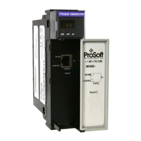
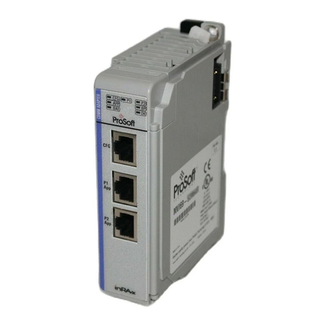
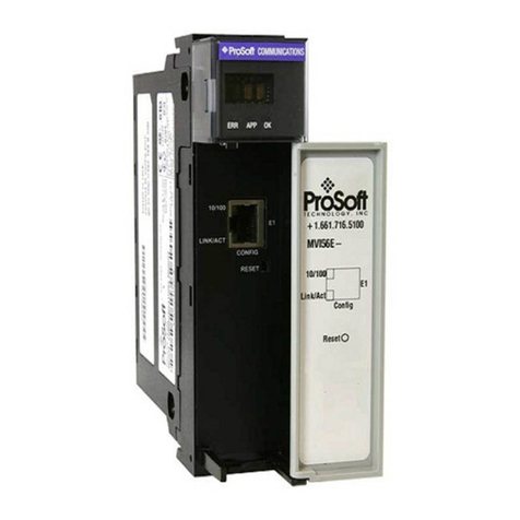
ProSoft Technology inRax MVI56E-GSC User manual
Other ProSoft Technology Control Unit manuals
ProSoft Technology
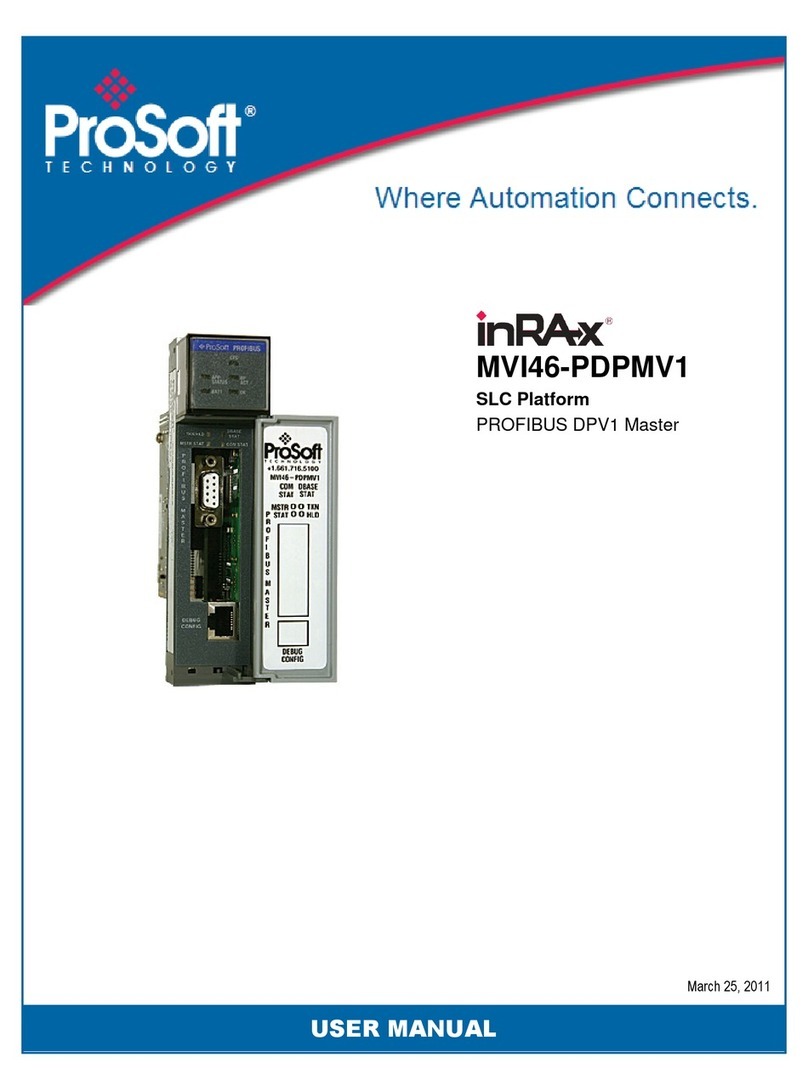
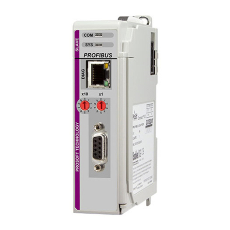
ProSoft Technology ILX69-PBS User manual
ProSoft Technology
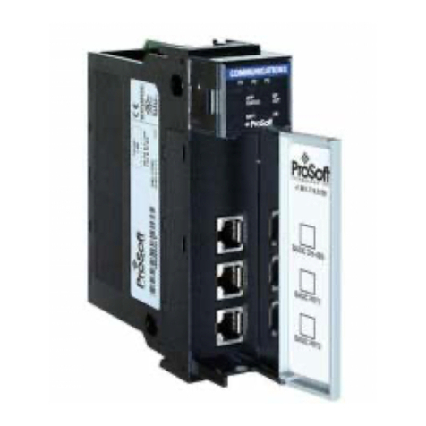
ProSoft Technology ControlLogix inRAx MVI56E-MNETR User manual
ProSoft Technology
ProSoft Technology inRAx MVI56-S3964R User manual
ProSoft Technology
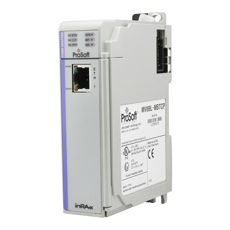
ProSoft Technology MVI69L-MBTCP User manual
ProSoft Technology
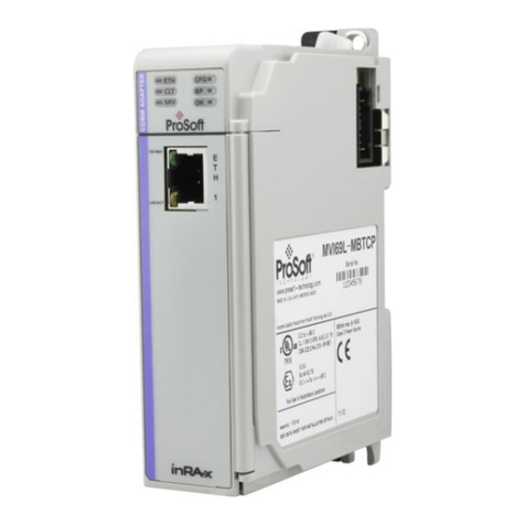
ProSoft Technology MVI69E-MBTCP User manual
ProSoft Technology
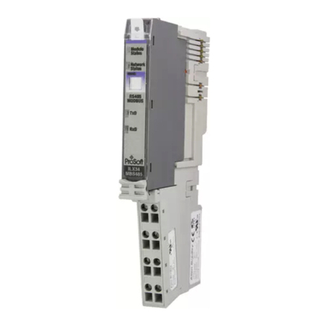
ProSoft Technology ILX34-MBS485 User manual

ProSoft Technology
ProSoft Technology inRAx MVI56-CAS User manual

ProSoft Technology
ProSoft Technology inRax MVI71-BDW User manual

ProSoft Technology
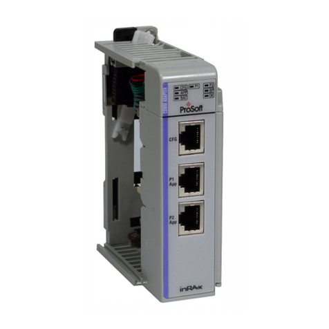
ProSoft Technology InRax MVI71-DNPSNET User manual
ProSoft Technology
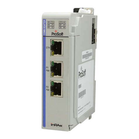
ProSoft Technology inRax MVI69-101M User manual
ProSoft Technology
ProSoft Technology MVI69E-GSC User manual

ProSoft Technology
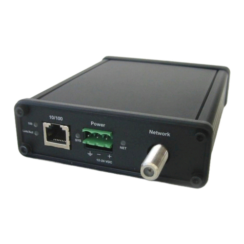
ProSoft Technology ProLinx ASCII Release note
ProSoft Technology
ProSoft Technology AN-X-MOD User manual
ProSoft Technology
ProSoft Technology InRAX MVI46-PDPS User manual
ProSoft Technology
ProSoft Technology ControlLogix MVI56E-SMGC User manual
ProSoft Technology
ProSoft Technology MVI56E-LDM User manual

ProSoft Technology
ProSoft Technology ILX800-SMSG User manual
ProSoft Technology
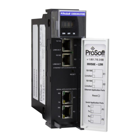
ProSoft Technology MVI56-PNPM User manual
ProSoft Technology
ProSoft Technology MVI56E-LDM-MQTT User manual
ProSoft Technology
ProSoft Technology PLX51-HART-4I User manual
Popular Control Unit manuals by other brands

Festo
Festo Compact Performance CP-FB6-E Brief description

Elo TouchSystems
Elo TouchSystems DMS-SA19P-EXTME Quick installation guide

JS Automation
JS Automation MPC3034A user manual

JAUDT
JAUDT SW GII 6406 Series Translation of the original operating instructions

Spektrum
Spektrum Air Module System manual

BOC Edwards
BOC Edwards Q Series instruction manual

KHADAS
KHADAS BT Magic quick start

Etherma
Etherma eNEXHO-IL Assembly and operating instructions

PMFoundations
PMFoundations Attenuverter Assembly guide

GEA
GEA VARIVENT Operating instruction

Walther Systemtechnik
Walther Systemtechnik VMS-05 Assembly instructions

Altronix
Altronix LINQ8PD Installation and programming manual

