Mobatime MOBALine-Booster User manual

© MOBATIME BE-800911.01
MOUNTING AND
INSTRUCTION MANUAL
MOBALine-Booster
Please read these instructions carefully before installation.

© MOBATIME 2 / 17 800911.01

© MOBATIME 3 / 17 800911.01
Product Certification
STANDARDS
The MOBALine-Booster was developed and produced in accordance with the EU Guidelines
2004 / 108 / EC
96 / 48 / EC
References to the Instruction Manual
1. The information in this Instruction Manual can be changed at any time without notice. The cur-
rent version is available for download at www.mobatime.com.
2. This Instruction Manual has been composed with the utmost care, in order to explain all details
in respect of the operation of the product. Please do not hesitate to contact us if you have any
questions. Thank you for reporting any possible mistakes.
3. We do not answer for direct or indirect damages which could occur when using this manual.
4. Read the instructions carefully. Only start setting-up the product if you have understood the in-
formation for installation and operation.
5. It is prohibited to copy this publication or to store it on a computer system. All rights reserved.
Copyright © BÜRK MOBATIME GmbH D-78026 VS-Schwenningen / GERMANY and
MOSER-BAER AG CH 3454 Sumiswald / SWITZERLAND.

© MOBATIME 4 / 17 800911.01
Content
1 Safety ............................................................................................................................................................5
1.1 Safety instructions.....................................................................................................................................5
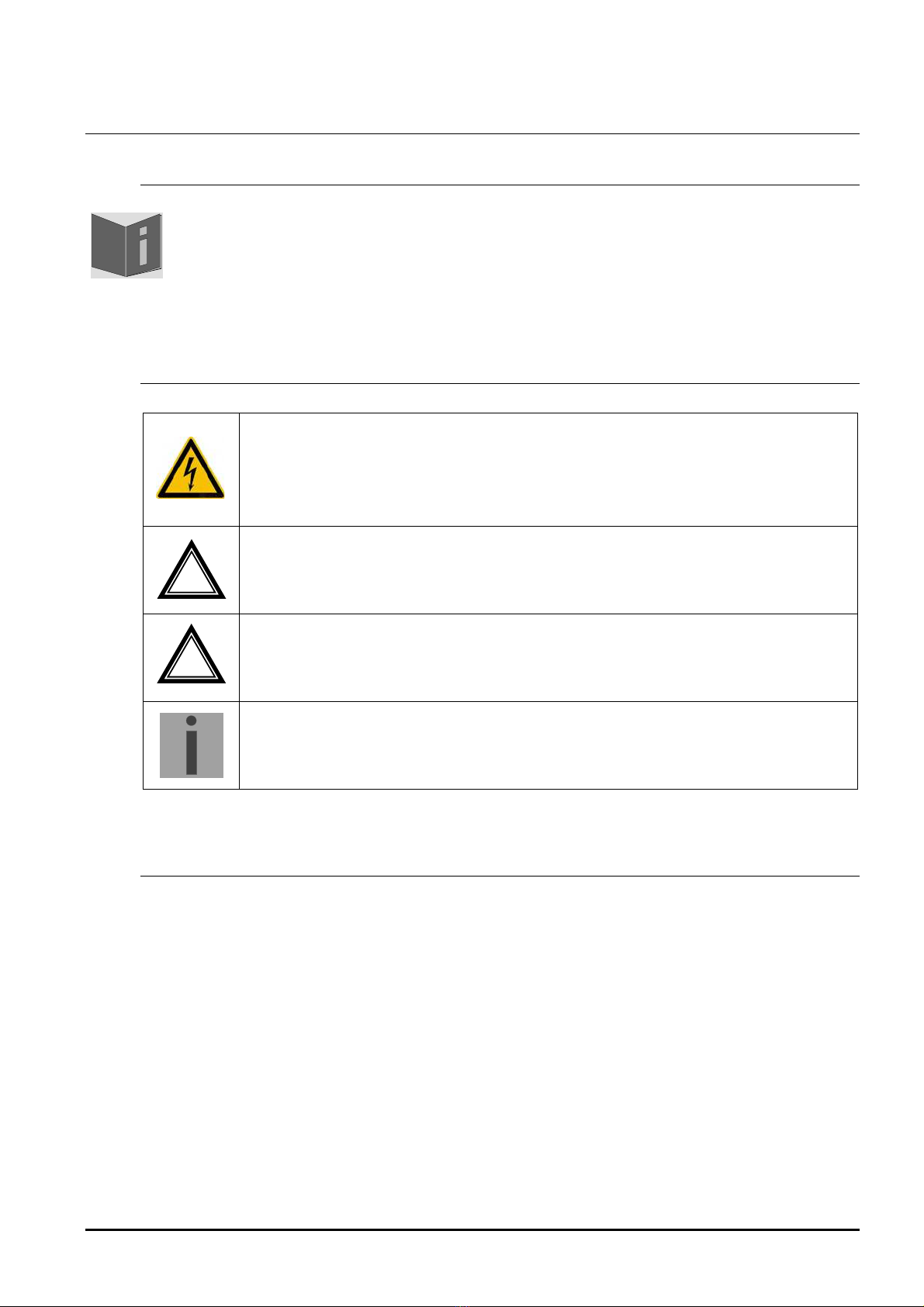
1.2 Symbols and Signal Words used in this Instruction Manual .....................................................................5
1.3 Intended use..............................................................................................................................................5
1.4 Observe operating safety! .........................................................................................................................6
1.5 Consider the installation site! ....................................................................................................................6
1.6 Observe electromagnetic compatibility! ....................................................................................................6
2 Maintenance ..................................................................................................................................................7
2.1 Troubleshooting: Repairs ..........................................................................................................................7
2.2 Cleaning ....................................................................................................................................................7
2.3 Disposing...................................................................................................................................................7
3 General Information: Introduction..................................................................................................................8
3.1 Scope of delivery.......................................................................................................................................8
3.2 Technical data...........................................................................................................................................8
3.3 Device designation in this manual.............................................................................................................8
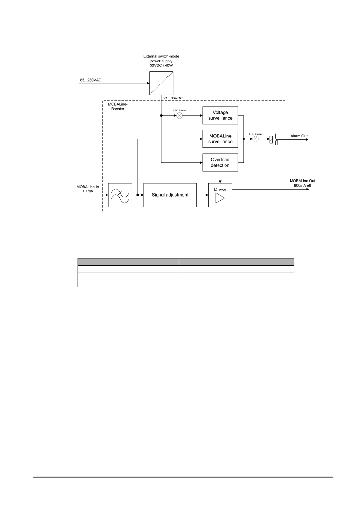
3.4 Function description ..................................................................................................................................8
3.4.1 Monitoring.......................................................................................................................................9
3.4.2 Alarm system..................................................................................................................................9
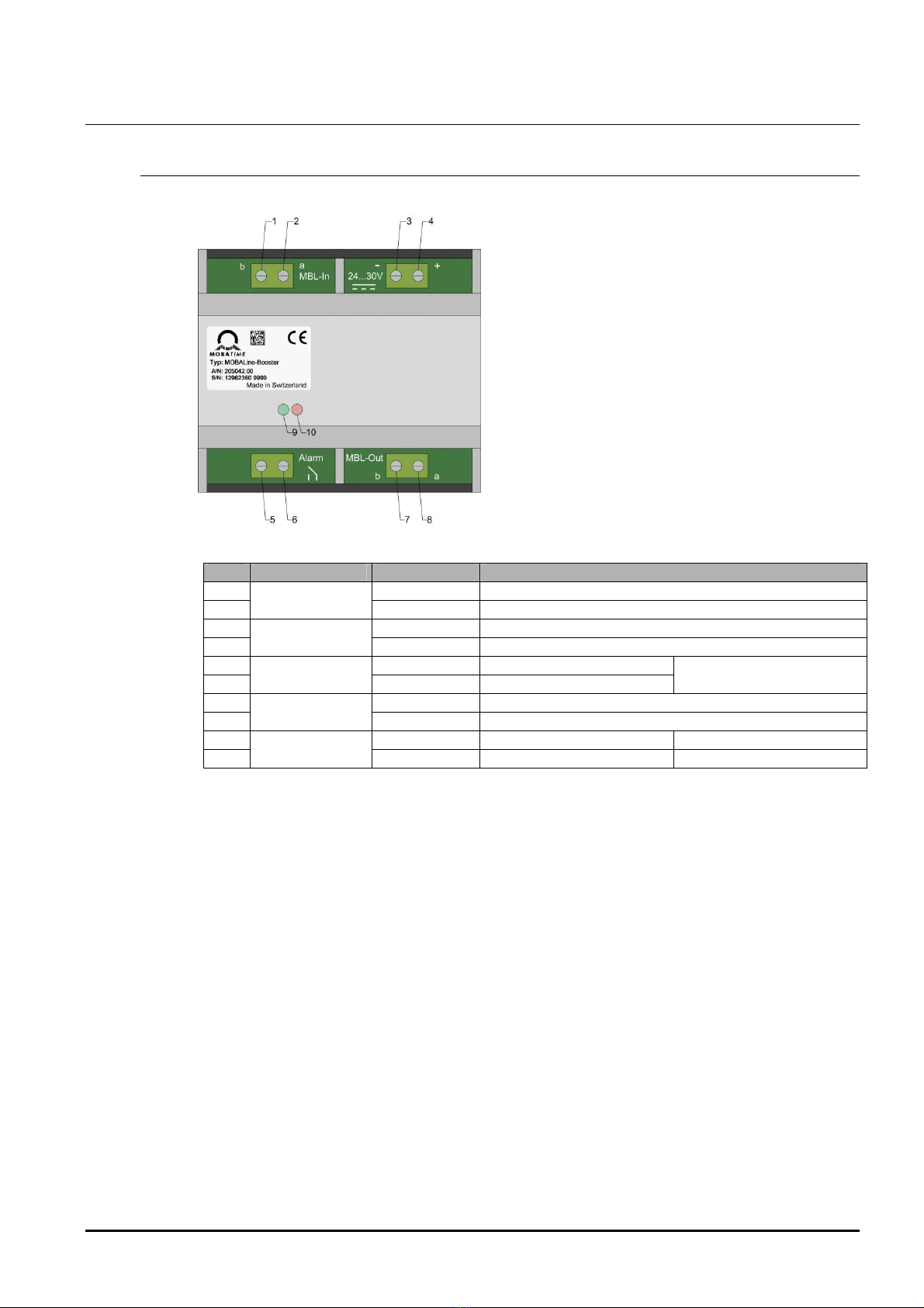
4 Configuration, displays and connections.....................................................................................................10
4.1 MOBALine-Booster .................................................................................................................................10
4.2 External switch-mode power supply........................................................................................................11
5 Mounting and installation.............................................................................................................................12
6 Application examples ..................................................................................................................................13
7 Technical data .............................................................................................................................................14
7.1 MOBALine-Booster .................................................................................................................................14
7.2 External switch-mode power supply........................................................................................................14
8 Dimensions..................................................................................................................................................15
8.1 MOBALine-Booster .................................................................................................................................15
8.2 External supply-mode power supply .......................................................................................................15

© MOBATIME 5 / 17 800911.01
1 Safety
1.1 Safety instructions
Read this chapter and the entire instruction manual carefully and follow all instructions
listed. This is your assurance for dependable operations and a long life of the device.
Keep this instruction manual in a safe place to have it handy every time you need it.
1.2 Symbols and Signal Words used in this Instruction Manual
Danger!
Please observe this safety message to avoid electrical shock!
There is danger to life!
Warning!
Please observe this safety message to avoid bodily harm and injuries!
Caution!
Please observe this safety message to avoid damages to property and devices!
Notice!
Additional information for the use of the device.
1.3 Intended use
The MOBALine-Booster is a device for the amplification of MOBALine lines with re-
gard to output and range.
Please refer to section 3.3 – Function description – for a detailed function description.
.
!
!

© MOBATIME 6 / 17 800911.01
1.4 Observe operating safety!
Never open the housing of the device! This could cause an electric short or even a
fire, which would damage your device. Do not modify your device!
The device is not intended for use by persons (including children) with limited physi-
cal, sensory, or mental capacities or a lack of experience and/or knowledge.
Keep packaging such as plastic films away from children. There is the risk of suffo-
cation if misused.
1.5 Consider the installation site!
To avoid any operating problems, keep the device away from moisture and avoid
dust, heat, and direct sunlight. Do not use the device outdoors.
The MOBALine-Booster is designed for DIN rails and should only be operated in-
stalled on a DIN rail.
By operating the device, the heat sinks attached to the sides get warm.
Make sure there is enough air circulation for the heat to dissipate.
Danger! Make sure
that you wait before using the device after any transport until the device has
reached the ambient air temperature. Great fluctuations in temperature or humidi-
ty may lead to moisture within the device caused by condensation, which can
cause a short.
1.6 Observe electromagnetic compatibility!
The device complies with the requirements of EMC directive 2004/108/EC and
96/48/EC
!
Caution!
!
Caution!

© MOBATIME 7 / 17 800911.01
2 Maintenance
2.1 Troubleshooting: Repairs
If you cannot rectify the problems, contact your supplier from whom you have pur-
chased the device.
Any repairs must be carried out at the manufacturer’s plant.
Disconnect the power supply immediately and contact your supplier, if …
liquid has entered your device
the device does not properly work and you cannot rectify this problem yourself.
2.2 Cleaning
Please make sure that the device remains clean especially in the area of the con-
nections, the control elements, and the display elements.
Clean your device with a damp cloth only.
Do not use solvents, caustic, or gaseous cleaning substances.
2.3 Disposing
Device
At the end of its life cycle, do not dispose of your device in the regular household rub-
bish. Return your device to your supplier who will dispose of it correctly.
Packaging
Your device is packaged to protect it from damages during transport.
Packaging is made of materials that can be disposed of in an environmentally friendly
manner and properly recycled.

© MOBATIME 8 / 17 800911.01
3 General Information: Introduction
3.1 Scope of delivery
Please check that the delivery is complete and notify your supplier within 14 days of re-
ceipt of the delivery if it is not complete.
In the package purchased by you, you have received:
MOBALine-Booster for DIN rail mounting
Switch-mode power supply (DIN rail mounting) for MOBALine-Booster
Wall mounting set comprising
DIN rails
Dowels and screws
Power supply cable between switch-mode power supply and MOBALine-Booster
3.2 Technical data
See chapter 7 Technical data.
3.3 Device designation in this manual
This manual relates to the MOBALine-Booster. For purposes of better readability the
designation booster is used in the following sections.
3.4 Function description
The MOBALine-Booster is a device for the amplification of MOBALine lines with regard
to output and range. For this purpose the MOBALine input signal is adapted and ampli-
fied.
The booster monitors the external supply voltage, the voltage of the MOBALine input
signal and the current of the MOBALine output signal (overload detection).
If one of the three monitoring systems detects an error, the booster switches off and
generates an alarm, which is signaled by the red alarm LED and with the alarm relay.
After five seconds the booster turns itself back on, provided that the monitoring system
has detected no further errors.
The signal is only amplified with the booster, therefore it is transparently transmitted,
i.e. without changes to content.
The booster is supplied by the external switch-mode power supply included in the
scope of supply, which can be operated directly from the power supply. If a power sup-
ply is available, the Power LED lights up.

© MOBATIME 9 / 17 800911.01
The following illustration shows the block circuit diagram of the MOBALine-Booster:
3.4.1 Monitoring
The MOBALine-Booster carries out the following tests to check for correct operation:
Test
Threshold value
Supply voltage
Lower than 21 V error
MOBALine input voltage
Lower than 9 V effective error
MOBALine output current
Higher than 800 mA effective error
3.4.2 Alarm system
The alarm output and the alarm LED acknowledge an active error only if it persists for
at least two seconds without interruption.
If the alarm output and the alarm LED have been activated, they remain activated for at
least five seconds, even if all errors have disappeared earlier.

© MOBATIME 10 / 17 800911.01
4 Configuration, displays and connections
4.1 MOBALine-Booster
The booster has the following connections and displays:
No.
Group
Caption
Meaning and function
1
MOBALine In b MOBALine input signal, connection b
2
a MOBALine input signal, connection a
3
Supply "-" Negative power supply connection
4
"+" Positive power supply connection
5
Alarm none Alarm relay connection Alarm = contact open
6
none Alarm relay connection
7
MOBALine Out B MOBALine output signal, connection b
8
A MOBALine output signal, connection a
9
Display none Power LED (green) ON: Power OK
10
none Alarm LED (red) ON: Alarm
The LEDs are located inside the case. However they are visible through the ventilation
slit in the case.

© MOBATIME 11 / 17 800911.01
4.2 External switch-mode power supply
The supplied switch-mode power supply DR-30-24 has the following connections, dis-
plays and controls:
No.
Type
Caption
Meaning
1Connection N Connection for the neutral conductor from the power
supply
2
Connection L Connection for the conductor from the power supply
3 & 4
Connection V+ Connections for the positive output voltage
5 & 6
Connection V- Connections for the negative output voltage
7
LED DC OK Status LED of DC output. ON = OK
8
Trimmer VADJ Control for adjustment of the output voltage

© MOBATIME 12 / 17 800911.01
5 Mounting and installation
To mount the MOBALine-Booster and activate it for the first time, the following procedure can
be followed:
1. Mount the DIN rail in the desired place.
2. Fit booster and switch-mode power supply DR-30-24 onto the rail.
3. Connect supply between switch-mode power supply and booster with the power supply
cable included in the scope of delivery. NB: The power supply cable does not have con-
nections of equal length on both sides:
a. From the power supply cable connect the blue wire with the longer wire-end sleeve
to connection V- (connection 5 or 6) of the switch-mode power supply.
b. From the power supply cable connect the brown wire with the longer wire-end
sleeve to connection V+ (connection 3 or 4) of the switch-mode power supply.
c. From the power supply cable connect the blue wire with the shorter wire-end sleeve
to connection - (connection 3) of the booster.
d. From the power supply cable connect the brown wire with the shorter wire-end
sleeve to connection + (connection 4) of the booster.
4.
Important:
Turn ADJ trimmer at the switch-mode power supply with a screwdriver
clockwise as far as it will go (set output voltage to maximum).
5. If necessary, connect the alarm output of the booster (connections 5 and 6).
6. Connect the MOBALine output of the booster (connections 7 and 8).
7. Connect power supply to the switch-mode power supply.
a. Connect neutral conductor to switch-mode power supply at N (connection 1).
b. Connect phase to switch-mode power supply at L (connection 2).
c. The DC OK LED of the switch-mode power supply and the Power LED (green) of
the booster must now light up. If not, the installation must be checked.
d. The alarm LED of the booster lights up as this still has no input signal.
8. Connect the MOBALline input of the booster (connections 1 and 2).
9. After a short time the alarm LED of the booster must go out.
The following illustration shows the power supply cable included in the scope of delivery (art.
no. 203004):
Booster Switch-mode power supply
(Short wire-end sleeves) (Long wire-end sleeves))
Length: approx. 200 mm

© MOBATIME 13 / 17 800911.01
6 Application examples
Up to 2 boosters can be used in a series. If more boosters are used serially, the signal gets distorted and can
not be reliably detected by clocks anymore.
Example 1: Airport
Example 2: Office building
long distance

© MOBATIME 14 / 17 800911.01
7 Technical data
7.1 MOBALine-Booster
MOBALine input Minimum level 10 Veff
Maximum load <1 mA
MOBALine output Maximum output load 800 mA
Output voltage 15 – 18 Veff
Supply Voltage range 24 – 30 VDC
Max. input current 1 A
Display Alarm LED (red)
Power LED (green)
Alarm relay DC output 30 W, max. 60 VDC or 1 A
AC output 60 VA, max. 30 VAC or 1 A
Environment Temperature 0…+70 °C
Dimensions 71.6 x 89.7 x 62.2 mm (W x H x D)
7.2 External switch-mode power supply
Model Mean Well DR-30-24
Order number 701722
Input AC voltage range 85 – 264 VAC
AC frequency range 47 – 63 Hz
DC voltage range 120 – 370 VDC
Output Output voltage 24 V (adjustable)
Output current 0 – 1.5 A
Temperature range –20…+60 °C
Dimensions 78 x 93 x 59 mm (W x H x D)

© MOBATIME 15 / 17 800911.01
8 Dimensions
8.1 MOBALine-Booster
8.2 External supply-mode power supply
Length 142 mm

© MOBATIME 16 / 17 800911.01

© MOBATIME BE-800911.01
Table of contents
Other Mobatime Network Hardware manuals