manuals.online logo
Brands
  1. Home
  2. •
  3. Brands
  4. •
  5. MOBB Health Care
  6. •
  7. Indoor Furnishing
  8. •
  9. MOBB Health Care MHOTAB User manual

MOBB Health Care MHOTAB User manual

Lifetime Limited Warranty
If you have a question about your MOBB Healthcare
device or this warranty, please contact an
authorized MOBB Healthcare dealer.
MOBB Healthcare warrants to the original
consumer purchaser for as long as they own their
MOBB product that it will be free from defects in
material and workmanship under normal use. This
warranty is only applicable to products used in
residential applications within the United States and
Canada and is not transferable to subsequent
owners. Should defects in material or workmanship
exist during the applicable warranty period in any
MOBB Healthcare Product, MOBB Healthcare will
elect at its discretion to either repair or replace the
defective material. This warranty covers only parts
and materials of the products supplied by MOBB
Healthcare. Not covered under this warranty are
wear and tear items or abuse of the product in a
manner that was not intended for the product to be
used. This warranty shall become void if the
product is in any way modified, improperly adjusted or
abused.
Non-Tilt Overbed Table
MHOTAB
MOBB Healthcare Lt
d
.
116A Viceroy Rd. Unit 5-6
Concord, Ontario, Canada
L4K 2M1
www.mobbhhc.com
MH
OTA
B
1. Remove contents from packaging and lay Table Top
(1) upside down on flat surface with Mounting Bracket
(5) facing upward. See Fig. 2.
2. Stand the Column Assembly (2) right side up as shown
in Fig. 1. Ensure Trip Rod (15) is visible in the rectan-
gular tube (as shown), but not protruding out of the
top. If necessary, shake the Column Assembly (2)
until the Trip Rod (15) drops into place inside the Col-
umn Assembly (2). Next, insert the Trip Lever (3), with
rounded side facing up, into the Column Assembly (2)
as shown, ensuring that the flat side of the Trip Lever
(3) rests on the Trip Rod. (15)
3. While holding the Trip Lever (3) securely in place on
top of the Trip Rod (15), flip the Column Assembly (2)
upside down and insert the Column Assembly (2) into
the table top Mounting Bracket (5) as shown in Fig. 2.
4. Align horizontal hole in table top Mounting Bracket
(5) with horizontal hole in Column Assembly (2) and
hole through Trip Lever (3). Insert / x 20 Bolt (4) into
horizontal hole & secure with Nut (4). Tighten with
10mm wrench. See Fig. 3.
5. Install two Domed Phillips Head bolts and locking
washers (6) through the vertical holes in the Mounting
Bracket (5) and into the threaded holes in Column As-
sembly (2) as shown in Fig. 4.
Assembly Instructions
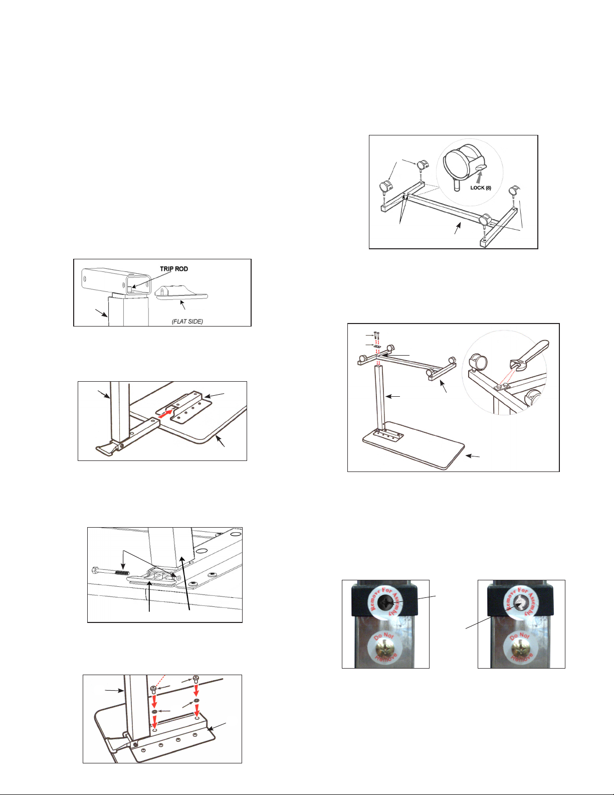
6. Install two Casters With Lock (8) into Base (7) which
connects to Column Assembly (2). Install two
Non-Locking Casters (9) into base opposite Column
Assembly (2). See Fig. 5.
7. Install two Bolt Sleeves (10) into upside down Base (7)
and then position two Bolts (12) through Bolt Plate
(11) and into Bolt Sleeves (10). Position Base (7) over
Column Assembly (2) and thread bolts into boom of
Column Assembly (2) and tighten using 16mm wrench.
See Fig. 6.
8. Turn the table upright and stand on casters.
9. CAUTION: This step must be completed last to
prevent damage to the spring loaded mechanism.
Remove the Black Screw (13) in the Column Assembly
(2) collar labeled “Remove for Assembly” and replace
it with the Chrome Screw (14) contained in hardware
package. Do not remove Chrome Screw labeled “Do
Not Remove”. See Fig. 7 and Fig. 8.
FIG. 3
4
32
FIG. 2 1
25
FIG. 1
(15)
TRIP LEVER (3)
2
6
6
FIG. 4
2
5
FIG. 7
Remove 13
FIG. 8
Insert 14
WARNING
FOR SAFETY – DO NOT REMOVE BLACK SCREW (13) ON COL-UMN ASSEMBLY
(2) UNTIL THE TABLE IS FULLY ASSEMBLED AND STANDING IN UPRIGHT
POSITION. AFTER REMOVING BLACK SCREW, REPLACE WITH CHROME SCREW
(14) INCLUDED IN HARDWARE PACKAGE.
THE BOTTOM CHROME SCREW WITH THE “DO NOT REMOVE” LABEL SHOULD
NEVER BE REMOVED AS IT WILL DAMAGE THE UNIT AND VOID YOUR
WARRANTY
12
11
2
FIG. 6
10
1
7
8
9
FIG. 5
Column end of base
with 2 holes 7
Assembly Precautions
This Overbed Table utilizes a high-tension spring loaded mech-
anism to raise the table, DO NOT remove #13 Black Screw and
replace with #14 Chrome Screw until table is fully assembled.
DO NOT over tighten bolts, screws or use power tools when
assembling this product.
Important Warnings
Please follow all instructions and warnings to avoid hazardous
situations that can result in property damage and/or patient/
resident/staff/caregiver injury and/or death.
Inspect the product for damage and loose hardware before each
use. DO NOT use the product if it appears to be damaged or
unstable and DO NOT modify the product in any way.
Intended Use
This product is designed for use as a movable patient/resident
table top surface for reading, eating, or keeping small personal
items such as glasses, telephone, or books within easy reach.
This product is designed for indoor use ONLY within close prox-
imity of skilled caregivers. It is not designed to hold electrical
items (such as televisions, computer monitors, coffee pots, etc.)
and should not be used near open flames and excessive heat.
Maximum weight limitation for this product is 50 lbs (22 kg.);
weight should be evenly distributed over the table top surface
while at the lowest usable height to help maintain a stable con-
dition.
DO NOT overload the product as that could result in breakage,
as well as damage to property and/or serious injury.
Use ONLY as directed for its intended use. This product should
NOT be used: as a sleep surface; as a walker or mobility aid to
assist a person in walking, siing down or standing up; to prevent
or brace a person’s fall; or to help transport persons or items.
Parts List
1. Table Top
2. Column Assembly
3. Trip Lever
4. / - 20 x 2 /” Bolt & Nut
(1 each)
5. Mounting Bracket
(Top to Column Assembly)
6. / - 12 x /” Domed Phillips
Head Bolt & Lock Washer
(2each)
7. Base
8. Casters with Lock (2 each)
9. Casters without Lock
(2 each)
10. Bolt Sleeves (2 each)
11. Bolt Plate
12. / - 15 x 2” Bolts (2 each)
13. Black Screw
14. Chrome Screw (to
replace #13 black screw)
15. Trip Rod /” x 20 /”
(inside Column Assembly)
Operating Instructions
To raise top to desired height, apply light pressure
upward at any point under table.
To lower, squeeze trip lever (3) up towards top and
push down at column to desired height. Do not put
pressure on tabletop end that is opposite the column.
Column assembly will lock upon release of trip lever.
1.
2.

Other MOBB Health Care Indoor Furnishing manuals

MOBB Health Care MHAM101 User manual

MOBB Health Care

MOBB Health Care MHAM101 User manual

MOBB Health Care Alternating Pressure Mattress User manual

MOBB Health Care

MOBB Health Care Alternating Pressure Mattress User manual

MOBB Health Care MHFTAB User manual

MOBB Health Care

MOBB Health Care MHFTAB User manual

Popular Indoor Furnishing manuals by other brands

IKEA PS 2012 Assembly instructions

IKEA

IKEA PS 2012 Assembly instructions

Glacier bay 30632 Assembly instructions

Glacier bay

Glacier bay 30632 Assembly instructions

Dell EMC ES40 Field Replacement Unit Guide

Dell EMC

Dell EMC ES40 Field Replacement Unit Guide

Coaster 106596 Assembly instructions

Coaster

Coaster 106596 Assembly instructions

Otto SORRENTO CREDENZA Assembly instructions

Otto

Otto SORRENTO CREDENZA Assembly instructions

Pfister Arkitek LG534-LPM Quick installation guide

Pfister

Pfister Arkitek LG534-LPM Quick installation guide

Glacier bay QL068 owner's manual

Glacier bay

Glacier bay QL068 owner's manual

Mocka Blair Assembly instructions

Mocka

Mocka Blair Assembly instructions

IKEA BUSSAN 103.129.11 manual

IKEA

IKEA BUSSAN 103.129.11 manual

Lesro Belmont Series Assembly instructions

Lesro

Lesro Belmont Series Assembly instructions

Lightolier IS-SIL_A-D instruction sheet

Lightolier

Lightolier IS-SIL_A-D instruction sheet

Husky HBR902490W5 manual

Husky

Husky HBR902490W5 manual

Emmezeta ANGEL 60 Assembling instructions

Emmezeta

Emmezeta ANGEL 60 Assembling instructions

Studio Designs ERGO PRO CHAIR 18409 Assembly instructions

Studio Designs

Studio Designs ERGO PRO CHAIR 18409 Assembly instructions

Habitat Petale 821792 manual

Habitat

Habitat Petale 821792 manual

Keter Harmony Assembly instructions

Keter

Keter Harmony Assembly instructions

Furniture of America CM-AC540S Assembly instructions

Furniture of America

Furniture of America CM-AC540S Assembly instructions

Kvik O841T Assembly instructions

Kvik

Kvik O841T Assembly instructions

manuals.online logo
manuals.online logoBrands
  • About & Mission
  • Contact us
  • Privacy Policy
  • Terms and Conditions

Copyright 2025 Manuals.Online. All Rights Reserved.