MobilePower POWER 400 User manual

MobilePower, LLC. Bluffton, SC 29910
www. Mobilepower-us.com Office: (800) 708 - 8550
support@mobilepower-us.com
customerservice@mobilepower-us.com
Sheet 1 of 12
Model No. 2001
POWER 400
Instruction Manual

POWER 400
6 in 1 POWER SUPPLY
with 400W inverter
400W Power
Inverter
Air Pressure Gauge
Polarity Indicator LED
Charging Jack/Port
Air Compressor ON/OFF Switch
Battery Charging
Indicator LED
LED Work light
ON/OFF Switch
Battery Charge Status
Dial Gauge
Double Injection Rubberized
Handle
LED Work light
12 VDC Socket with
Protective Dust Cover
12 VDC Socket with
Protective Dust Cover
USB / Inverter Power Switch
USB power ON position —
Inverter Power LED Indicator
Double Injection Rubberized
Protective Padding
Battery Cable/Clamp
Positive
Main Booster Power Switch
Inverter Blade Fuse
Compressor Air Hose and
accessories compartment
Model No. 2001
Packaging includes
the following accessories:
110 VAC Charging adaptor
12 VDC Charging adaptor
Compressor Air Valve Accessories
Operating Instruction Manual
Dual 12 Volt DC Booster Cable USB Port 2100mA
Inverter Power Switch
Inverter power ON position =
USB power ON position —
Inverter power ON position =
Power OFF position
Battery Charge Status
Indicator Push Button
Inverter cooling fan
Sheet 2 of 12
IMPORTANT INFORMATION
READ AND UNDERSTAND ALL WARNINGS AND THE ADVISORY NOTES INCLUDED IN THIS
MANUAL. FOLLOW INSTRUCTIONS PROVIDED BY YOUR VEHICLE MANUFACTURER AND MAN-
UFACTURER OF THE DEVICES INTENDED TO BE USED WITH THIS POWER SUPPLY.
MAKE CERTAIN THIS DEVICE IS FULLY CHARGED PRIOR TO FIRST USE.
WARNINGS
THIS PRODUCT CONTAINS A SEALED LEAD-ACID BATTERY AND MUST BE DISPOSED OF
PROPERLY. YOU MAY CONTACT YOUR LOCAL GOVERNMENT RECYCLING AUTHORITY FOR
APPROPRIATE DISPOSAL. FAILURE TO FOLLOW THE INSTRUCTIONS MAY CAUSE DAMAGE
TO THE PRODUCT AND OR PERSONAL INJURY.

IMPORTANT ADVISORY NOTES
Do not use with dry cell batteries. These batteries may burst and cause injury to person or damage
personal property.
Do not attempt to face the battery being jumped. Stay away as far as possible from the battery when
making the final connection.
DO NOT CONNECT TO or jump start a 6 or 24 Volt battery.
If battery acid comes in contact with skin or eyes, rinse immediately with water for 20 minutes. Seek
medical attention if redness, irritation or pain is present.
DO NOT smoke, use matches, lighters or an open flame near batteries.
This products contains chemical substances including lead. Wash hands thoroughly after handling
Lead Acid Batteries.
Never allow red (Positive) and black (Negative) clamps to come in contact with each other or
contact with metal object at the same time.
To protect against electrical hazards, do not immerse charger, adapters, or unit in water or other
liquid.
Close supervision is necessary when working near children.
Do not use unit for applications other than its intended use.
Always connect the red (+) clamp to the positive battery terminal first. Connect black (-) clamp to the
negative battery terminal as final connection.
Jumpstart vehicles in a well ventilated area only.
Do not expose Power 400 to moisture and use it in extremely hot conditions.
Monitor the pressure gauge during use. Be careful not to over-inflate objects.
Never work alone with this product. Make sure that someone is available to give assistance if need-
ed.
Wear complete eye and clothing protection. Do not touch eyes while working near battery.
Do not attempt to remove or replace the battery used in this device. When the battery has reached
the end of its useful lifetime, take the entire unit to a battery recycling facility.
For proper and safe operation of the 12 Volt DC power accessory outlets, do not place anything into
it except the plug of the accessory to be used.
Remove metal, personal jewelry, such as: rings, bracelets, necklaces and watches, while working
with a lead acid battery. This can produce a short-circuit that may cause severe burns.
Never charge or jump-start a frozen battery.
Do not operate this device while wearing vinyl clothing. Static electricity may be generated when
vinyl clothing is rubbed.
This product is not intended for use in the rain or temperatures above 150ºF.
Use only the provided chargers, cables and clamps. Unauthorized parts may damage the unit.
This product has no consumer serviceable parts except the replaceable fuses.
Keep out of the reach of children.
Keep battery terminals clean. Be careful to keep corrosion from coming in contact with eyes.
Do not let the cords of the Power 400 or jumper clamps get wet.
Prevent water to get into Power 400 housing. Water will damage the internal electronics board.
This unit has a built-in lead acid battery. Although Power 400 arrives partially charged from the
factory, it MUST be fully charged before the first use.
Recharge Power 400 after each use or every 3 months preventing the battery voltage to become
extremely low.
Sheet 3 of 12
Model No. 2001

FEATURES:
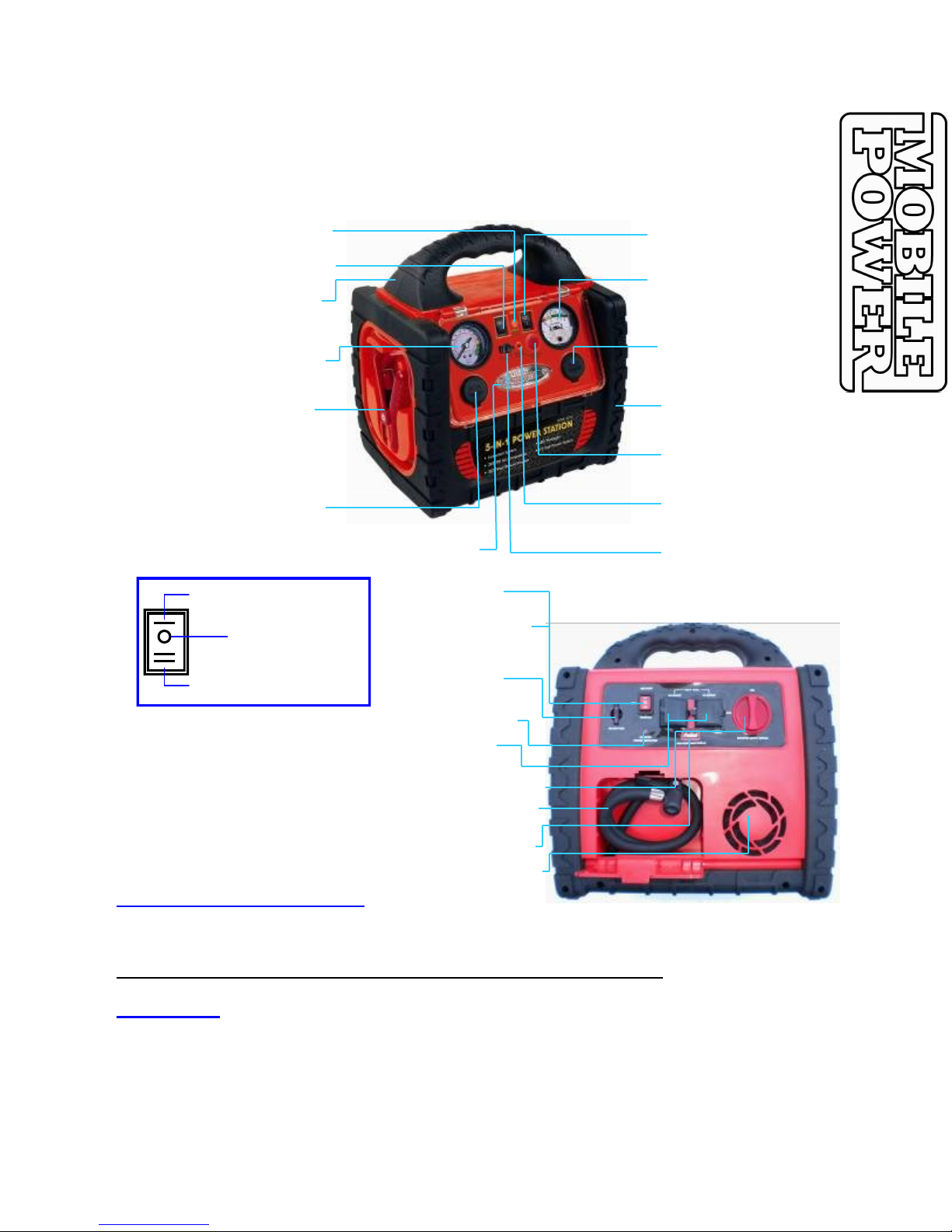
Compact 6 in 1 multipurpose AC and DC power supply with vehicle jumpstart boosting system. The unit
provides: two 12 VDC covered output ports, 400 Watt continuous power inverter with 120 VAC covered
outlet, Air Compressor, Booster Cables with Insulated Clamps, Booster Cables Power Switch, Nozzle
Adaptors for most Inflatables, LED working light, Reverse Polarity Protection, Battery Status Needle Dial
Gauge, Dual 12 Volt DC Accessory plugs Charge/Booster Cable through vehicle 12 Volt DC cigarette
lighter socket, USB power port with vehicle instant battery jump starter.
SPECIFICATIONS:
BUILT-IN 12V 18AH RECHARGEABLE LEAD ACID BATTERY.
INSTANT BATTERY JUMP STARTER.
DUAL 12 VDC COVERED OUTPUT PORTS.
USB POWER SUPPLY OUTPUT PORT.
HIGH POWER 400 WATT CONTINUOUS/800 WATT PEAK POWER INVERTER
WITH 2 x 120 VAC COVERED OUTLETS.
AIR COMPRESSOR WITH NEEDLE DIAL GAUGE.
REVERSE BATTERY POLARITY DETECTION CIRCUITRY.
ULTRA BRIGHT WHITE LED CONVENIENCE.
COMPACT AND PORTABLE SIZE WITH RUBBERIZED HANDLE.
NOZZLE ADAPTORS FOR INFLATABLES.
AC & DC CHARGERS ARE INCLUDED.
CHARGING POWER 400 INSTRUCTIONS:
CAUTIONS
Prior to charging this device, read and understand all the related instruction indicated below.
Fully charge the Power 400 unit when the Battery Status Needle Dial reads below 12 VDC.
This product may arrive partially charged from the factory. It is highly recommended to fully
charge the Power 400 unit after purchase and before using for the first time.
Make certain that all ON/OFF Power Switches are set in the OFF position.
Do not charge the Power 400 Power Supply near flammable material, open flame or any
location which accumulate flammable fumes.
Make certain the electrical outlet located in a potentially wet or moist area that is to be used
to charge this device, is protected by a Ground Fault Circuit Interrupter (GFCI).
Make sure that both booster clamps are securely placed in their designated storage
compartments when not in use and during the charging period.
A. AC Charging At Home with 110 Volt Charger
1. Keep the Main Booster Power Switch in OFF position while charging.
2. Insert the AC charger round plug into the Power 400 Charging Port.
3. Connect the 110 Volt AC Charger into the 110 Volt AC home receptacle.
4. Fully charge the Power 400 according to the following schedules:
First time charge: 36 hours
Recharge and subsequent charge: 24 hours
5. Unplug the AC charger from the 110 Volt receptacle first and then remove the round plug from the
Power 400 Charging Port.
B. DC Charging In Your Vehicle with 12 Volt Charger
1. Keep the Main Booster Power Switch in OFF position while charging.
2. Insert the 12 Volt DC Charger round Plug into the Power 400 Charging Port.
3. Connect the 12 Volt DC Charger Plug into the vehicle cigarette lighter or 12 Volt accessory port.
4. Fully charge the Power 400 internal battery for 8 hours while the vehicle engine is running.
5. Unplug the DC charger from the vehicle cigarette lighter or 12 Volt accessory port first and then
remove the round plug from the Power 400 Charging Port.
Model No. 2001
Sheet 4 of 12

INTERNAL BATTERY CHARGE LEVEL:
Press and hold the Battery Charge Level Status Push Button to determine the unit internal
battery charge level prior to each use.
The Battery Charge Status Dial Gauge Needle will indicate the battery charge level.
AIR COMPRESSOR OPERATING INSTRUCTIONS:
CAUTIONS
Do not operate the Air Compressor more than 15 Minutes continuously. Allow the
compressor to cool down for 10 to 15 minutes between each continuous operation.
Review the products to be inflated for manufacturer’s recommended maximum inflation
pressure. Most tires are recommended to be inflated between 27 to 38 PSI.
Always check the air inflation pressure with a separate and reliable pressure gauge during
and after inflation.
A. TO INFLATE TIRES:
1. Open the Compressor Air Hose Compartment access door at the left side of the Power 400 and pull
out the air hose. Make sure that the Nozzle Locking Lever is in the UP position.
2. Remove the valve cap from the tire valve stem.
3. Attach the compressor air valve nozzle onto the tire air valve stem and push down the air valve
nozzle as far as it travels. Make certain it is seated properly.
4. Press down the Nozzle Locking Lever all the way down to securely lock the tire air valve stem.
IMPORTANT: If the tire is completely deflated, raise the vehicle by utilizing a recommended rated
lifting device and jack stand before inflating the tire.
5. Turn the compressor switch located on the front panel of Power 400 to ON position.
6. Monitor the pressure on the compressor air pressure gauge while inflating.
7. Turn OFF the compressor when the desired tire air pressure is reached.
8. Disconnect the air hose nozzle from the tire air valve stem by lifting Nozzle Locking Lever to the UP
position.
9. Replace the tire valve cap onto the tire valve stem.
10. Stow the air hose into the Compressor Air Hose Compartment.
B. TO INFLATE BALLS/AIR MATTRESSES/RUBBER RAFTS:
1. Open the Compressor Air Hose Compartment access door at the left side of the Power 400 and pull
out the air hose. Make sure that the Nozzle Locking Lever is in the UP position.
2. Remove the valve cap from the inflatable valve stem.
3. Attach the appropriate valve stem adaptor to the Air Hose Nozzle.
4. Press down the Nozzle Locking Lever all the way down to securely lock the valve stem adaptor.
5. Attach the compressor air valve nozzle with the valve stem adaptor onto the air valve stem of the
inflatable and push down the air valve Nozzle as far as it travels. Make certain it is seated properly.
6. Turn the compressor switch located on the front panel of Power 400 to ON position.
7. Monitor the pressure on the compressor air pressure gauge while inflating.
8. Turn OFF the compressor when the desired air pressure is reached.
9. Disconnect the air hose nozzle from the air valve stem.
6. Replace the valve cap onto the valve stem.
7. Stow the air hose into the Compressor Air Hose Compartment.
Model No. 2001
Sheet 5 of 12
Red Zone: Low Battery Charge Level - Charge immediately.
Yellow Zone: 10% - 50% Charge Level - Recharge before use.
Green Zone: 51% - 100% Charge Level - Recharge after use.
Press and HOLD
Table of contents
Popular Power Supply manuals by other brands

Videx
Videx 520MR Installation instruction

Poppstar
Poppstar 1008821 Instructions for use

TDK-Lambda
TDK-Lambda LZS-A1000-3 Installation, operation and maintenance manual

TDK-Lambda
TDK-Lambda 500A instruction manual

Calira
Calira EVS 17/07-DS/IU operating instructions

Monacor
Monacor PS-12CCD instruction manual