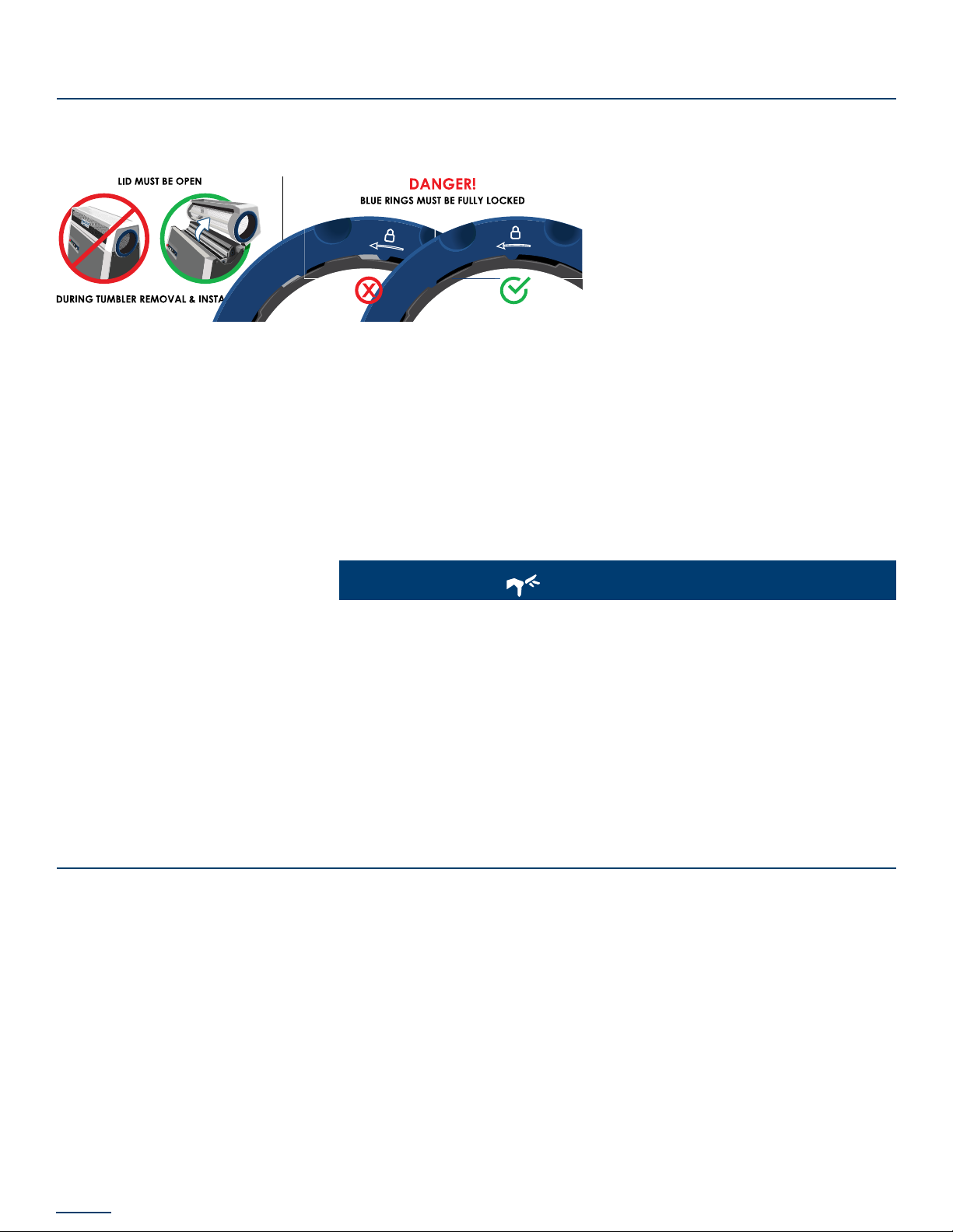
Mobius Trimmer M108S User manual

USER GUIDE
©2020 ETEROS TECHNOLOGIES INC. ALL RIGHTS RESERVED. | UG2004M108S

INTRODUCTION
Thank you for purchasing the Mobius Trimmer M108S, the world’s best cannabis and hemp trimmer.
When properly congured and operating within design specications, this industrial agricultural
material processing machine offers unrivalled output and a nished product almost indistinguishable
from hand-trim.
The information available in this guide will provide you with a thorough understanding of how to
safely use this device to maximum effect. Please heed all safety warnings and instructions as they are
critical for safe and effective use of the equipment. The M108S is a signicant step forward in trimming
technology and may operate differently than you are accustomed to. Following the instructions in this
guide will allow you to benet from these innovations.
If you have any questions or encounter topics not covered in this guide, please feel free to reach out
to your location of purchase, or Mobius directly. Should you want additional, one-on-one training or
to certify a Mobius Lead Operator, please reach out to Mobius directly for information on training
services. Mobius also offers consulting services for automation integration and for setting up the ideal
trim room, along with accessories for cleaning and component storage for your M108S.
We hope you enjoy your trimming experience with the M108S. Happy trimming!
This User Guide is a comprehensive manual covering the operation and maintenance of the MOBIUS
TRIMMER M108S processing machine as of the date of publication. ETEROS TECHNOLOGIES reserves the
right to make updates to the machine from time to time. In the event of an update, this User Guide
will remain appropriate for the safe operation and maintenance of your unit. This User Guide, as well
as any documentation supplied by component manufacturers, are to be considered the information
package associated with this device. Every operator must read and understand the User Guide. The
manual should be located within easy access for periodic review.
For the most up to date version of this manual, please refer to the manufacturer’s website at
mobiustrimmer.com
NOTES:

TABLE OF CONTENTS
SAFETY INSTRUCTIONS
DISCLAIMER
WARNING LABELS
SERVICE & REPAIRS
GENERAL SAFETY PRECAUTIONS
5
5
6
6
7
SAFETY 4
UNCRATING
REASSEMBLY
CONVEYOR SETUP
TANDEM SETUP
13
15
19
21
SETUP 12
APPENDICES 37
M108S
AIRTHREAD TENSION TUMBLER
TRIFLEX BLADE SYSTEM
VARIABLE SYSTEM CONTROL
WHAT’S IN THE CRATE
9
10
10
11
11
MACHINE OVERVIEW 8
OPERATION PREP
GENERAL OPERATION
HOT SWAPS
WET TRIMMING
DRY TRIMMING
TIPS & TRICKS
23
23
26
27
28
29
OPERATION 22
CLEANING
PREVENTATIVE MAINTENANCE
EXPECTED SERVICE LIFE OF STANDARD WEAR PARTS
WARRANTY
SPECIFICATIONS
32
32
34
35
36
GENERAL 31

MOBIUS TRIMMER M108S USER GUIDE
4
SAFETY

5
MOBIUSTRIMMER.COM
SAFETY INSTRUCTIONS
To ensure operator safety while in use, this device includes decaling, guarding, and other safety features.
Operators are encouraged to use caution and best judgment when using equipment. Equipment
should be serviced when required.
To avoid possible damage to the machine and risk of injury to the operator, consult with an ETEROS
TECHNOLOGIES representative to answer any questions.
This document refers to the ETEROS TECHNOLOGIES product trimming machine as the M108S. Since this
machine has moving blade components, special safety precautions must be observed to reduce the
risk of personal injury. Careless or improper use may cause serious or even fatal injury. Please read and
understand these precautions thoroughly before using the machine.
All operators must read and understand this User Guide and be trained in safe operation and use of
the M108S. We recommend the owner of this equipment develop a standard operating procedure
specic to each worksite to address any local hazards or other conditions not outlined in this User
Guide. The M108S must be inspected regularly for damage, component failure, and wear. Results of
inspection activity should be documented.
ETEROS TECHNOLOGIES makes every effort to ensure the M108S is compliant with all current safety
standards. It is the responsibility of the owner to ensure all municipal, provincial, state, county, territorial,
and federal codes, regulations and standards have been met in each working location. Do not lend
or rent your machine without providing the User Guide. A rst-time operator should receive practical
instruction before using the machine.
This machine is not to be used for any purpose other than those expressly stated in the User Guide,
advertising literature, or other ETEROS TECHNOLOGIES written material pertaining to the M108S.
Operators must be in good physical condition and mental health to operate this device. Under no
circumstances should the device be operated by anyone under the inuence of any substance,
including drugs or alcohol, which might impair vision, dexterity, or judgment. Do not operate the M108S
when fatigued. Be alert. If tired while operating the device, take a break. Fatigue may result in loss
of control. Working with any equipment can be strenuous. If you have any condition that might be
aggravated by strenuous work, check with your doctor before operating the device.
DISCLAIMER
ETEROS TECHNOLOGIES recognizes that the M108S is a purpose-built machine for processing cannabis
and hemp by licensed producers. Please check all municipal, provincial/state, and federal laws and
regulations before using the M108S. ETEROS TECHNOLOGIES does not promote or condone the use of
processing equipment in any way that may be deemed illegal.
It is not the responsibility of ETEROS TECHNOLOGIES to conrm alternative equipment applications.

MOBIUS TRIMMER M108S USER GUIDE
6
WARNING LABELS
SERVICE & REPAIRS
Minor repairs may be carried out by the end-user under the guidance of Eteros Technologies. Any
other repair work may only be carried out by Eteros Technologies or a designated authorized agent
(service technician).
Should the need arise, please notify:
ETEROS TECHNOLOGIES
17665 66A AVE. UNIT 202
SURREY, B.C. V3S 2A7
1-866-874-6244
Improper interfacing, improper repair, or unauthorized modication could result in void warranty claims.
WARNING
IMPELLER CONTINUES MOVING AFTER ENGAGING E-STOP.
DO NOT REMOVE FILTER BAG UNTIL IMPELLER COMES TO A FULL STOP.
LA ROUE À AUBES CONTINUE À TOURNER MÊME APRÈS L’ENGAGEMENT DE L’ARRÊT D’URGENCE.
NE RETIREZ PAS LE FILTRE À MANCHES JUSQU'À CE QUE LA ROUE À AUBES SOIT COMPLÈTEMENT ARRÊTÉE.
AVERTISSEMENT

7
MOBIUSTRIMMER.COM
GENERAL SAFETY PRECAUTIONS
1. READ and become familiar with the entire User Guide. LEARN the equipment applications, limitations,
and possible hazards.
2. KEEP GUARDS IN PLACE and in working order.
3. DO NOT USE THE DEVICE IN A DANGEROUS ENVIRONMENT or damp or wet locations. Never expose
control panel directly to rain or water. Keep work area well illuminated.
4. DO NOT use the device in the presence of ammable liquids or gases.
5. KEEP WORK AREA CLEAN. Cluttered areas and workspaces invite accidents.
6. KEEP CHILDREN and BYSTANDERS AWAY from the device. Visitors should be kept at a safe distance
from the work area.
7. DON’T FORCE THE EQUIPMENT. It will operate optimally and safely at the rate for which it was
designed.
8. USE THE RIGHT TOOL. Don’t force the device to do a job for which it was not designed.
9. ALWAYS WEAR EYE PROTECTION when the equipment is operational or when maintaining the
equipment.
10. ALWAYS WEAR EAR PROTECTION when the equipment is operational.
11. WEAR PROPER APPAREL. Do not wear loose clothing, gloves, neckties, rings, bracelets, or other
jewelry which may get caught in moving parts. Non-slip footwear is recommended. Wear protective
hair covering to contain long hair.
12. POWER DOWN AND DISCONNECT EQUIPMENT before servicing and when changing accessories,
such as tumbler, blades, etc.
13. INSPECT MACHINE AND REMOVABLE PARTS PRIOR TO OPERATION. The equipment should be
inspected prior to use to ensure proper operation in performing its intended function. Check for
damage, alignment of moving parts, binding of moving parts, breakage of parts, mounting, and
any other conditions that may affect its operation. Any damaged part including guards should be
properly repaired or replaced. Ensure that electrical box lter is in place and clean.
14. ALWAYS OPERATE DEVICE IN A WELL-VENTILATED AREA. Dust generated from certain materials can
be a health hazard. Use a dust collection system whenever possible. If dust extraction is not installed,
a face or dust mask should be worn.

MOBIUS TRIMMER M108S USER GUIDE
8
MACHINE OVERVIEW

9
MOBIUSTRIMMER.COM
MOBIUS TRIMMER M108S
Control Panel
Hex Screens
Left Front Sensor Block
E-Box Filter
Clear Top Screen
Outfeed
Separator
Fan Housing Air Filter
Trim Tote
Tumbler
Fan Housing
Infeed
Hockey Stick
Spare Belt
Tilt Legs
Accessory Caddy
Right Rear Sensor Block
Belt, Gears & Pulleys
TriFlex Blade Cartridges

MOBIUS TRIMMER M108S USER GUIDE
10
AIRTHREAD TENSION TUMBLER
TRIFLEX BLADE SYSTEM
Spacer Bar
Helical Blade
Gear Side
Bearing Block
Spacer Bar Pin
Bed Knife Pin
Bed Knife
Bed Knife
Spacer Bar
END VIEWS:
Infeed End Cap
Infeed Tab
Outfeed End Cap
Tumbler Rings
Tumbler Ring

11
MOBIUSTRIMMER.COM
VARIABLE FUNCTION SYSTEM
WHAT’S IN THE CRATE
Your MOBIUS TRIMMER M108S comes with the following items:
• POWER CORD
• 1 SPRING JACK TOOL to install and remove the tumbler
• 2 AIRTHREAD TENSION TUMBLERS
• 2 TRIM TOTES
• 1 FAN HOUSING FILTER BAG
• 2 REPLACEMENT E-BOX FILTERS
• 2 BLUE TUMBLER RETAINING RINGS
• INSTRUCTIONAL POSTERS: 6-Point Blade Inspection, Tumbler Inspection, E-box Filter Installation
Tumbler Installation.
• A PAIR OF TANDEM LOCKS (if you plan to run 2 machines together).
• A PAIR OF BLACK OVERRIDE PUCKS (if you plan to use conveyors instead of the hopper and
chute).
• 1 INFEED HOPPER and 1 OUTPUT CHUTE (US VERSION ONLY)
Fault Display
E Stop Start Blade
Speed
Vacuum
Suction
Tumbler
Speed
Tilt
Angle
Mobius
Button
Control Panel Display

MOBIUS TRIMMER M108S USER GUIDE
12
SET-UP

13
MOBIUSTRIMMER.COM
1. Remove the crate lid and 1 side panel
4. Remove protective plastic from M108S
and retain for future use
7. Pull up on levers holding the installed
trim tote and rotate them downwards
10. Place hand in the gap to support the
weight of the separator and pull it the
rest of the way out Place separator on
foam sheet
5. Remove blue plastic wrap holding
additional components to the body of
the machine (Spring Jack Tool, and extra
Trim Tote)
8. Slide trim tote out and set aside
11. Slide fan housing off pegs and remove
from the body. Place it on the foam sheet
with the separator.
6. Place foam sheet on ground to be used
as a protective barrier for other removed
components
9. Push down ‘hockey stick’ lever to unlock
the separator and slide the separator out
until a hand-sized gap is visible
2. Remove 2 boxes containing the hopper
and chute, set aside 3. Remove 3 remaining side panels
To remove the body of the Mobius from the crate base, you’ll want to disassemble a portion of the
machine to decrease the weight before lifting it.
To do so, please follow these steps. For a video showing the following process, please refer to the
Uncrating video in our Mobius Academy.
UNPACKING THE MOBIUS TRIMMER:
REMOVING COMPONENTS TO REDUCE WEIGHT:
UNCRATING

MOBIUS TRIMMER M108S USER GUIDE
14
REMOVING LID:
12. Open lid by sliding the 2 latches towards
each other, and then rotating the lid
away from you
15. Lift each bed knife out of machine
and place to the side, preferably in a
Mobius Blade Rack
18. Rotate wheels outward and unlock
casters 20. Lift the machine straight up to clear
the wooden anchor below each wheel.
Walk the machine to the side until it clears
the crate-base. Set machine down and
re-`lock the wheels .Remove power cord
from crate base
13. Disconnect the wire between the lid
and the M108S body
16. Lift each spacer bar out of machine
and place to the side, preferably in a
Mobius Blade Rack
19. Remove the four retaining straps that
anchor the machine to the crate base.
Rotate the handles on each side of the
M108S outward.
Note: 4 people should lift the M108S off
the crate base with 1 person per handle
14. With two people, slowly rotate the lid
towards the closed position while pulling
up on it. When the hinges reach the
correct position, the lid will release from
the machine body. Place the lid aside.
17. Lift each helical blade out of machine
and place to the side, preferably in a
Mobius Blade Rack
For more in depth instructions, see the Academy video on lid removal.
REMOVING BLADE CARTRIDGES:
REMOVING MOBIUS TRIMMER BODY FROM CRATE BASE:

15
MOBIUSTRIMMER.COM
1. Place each helical blade into its housing
in the correct orientation (gear on blade
interlocks with gear on machine)
3. Place the lid hinge on the body hinge and slowly rotate the lid toward the front of the
machine in the closing motion As the lid closes, it will slide forward into the body hinge
Slowly rotate the lid toward the open position and the lid will lock in the rest of the way.
5. The fan housing ts into the body by resting on 2 pegs. Holes in the fan housing correspond to the pegs on the body. Align the holes
to the pegs and slide the fan housing into place. Ensure the housing sits ush against the body to allow the separator to t without
binding against it.
6. Note: The separator mates to the machine resting on a guide rail inside the frame. Grip the separator from the opening and the
rear (trim tote side) of the housing. Align the separator so it is above the rail on the machine and push it in along the rail. When the
weight of the separator is carried by the rail, let go of the opening and slide it the rest of the way into the machine.
4. Reconnect the lid wire to the M108S
body. Close the lid.
Note: Gloves should be worn when handling the helical blades and any sharp objects
Note: The helical blade must be placed in the machine in the correct orientation. One side of each helical blade has a gear that
corresponds to a gear on the outfeed side of the machine.
INSERTING THE BLADE CARTRIDGES
Once the machine has been removed from the base, you can start to reassemble it to get ready for
trimming. View the video online, or follow along below. Please do so in the following order:
REASSEMBLY
2. Note: The spacer bar sits on the far side of the helical blade, and the bed knife sits
on the near side. Spacer bars and bed knives must be placed into the machine in the
correct orientation. Each has a pin on one side that corresponds with the outfeed side
(gear side) of the machine. Slide each bed knife and spacer bar into place around
the helical blades
INSTALLING THE LID
INSTALLING THE FAN HOUSING AND SEPARATOR
View the video online, or follow along below. Please do so in the following order:

MOBIUS TRIMMER M108S USER GUIDE
16
7. Pull up the hockey stick lever until the
top of the stick is ush with the top of the
separator to lock it in place
8. With the Trim Tote gasket seam facing
in, slide the Trim Tote onto the rails of the
separator
9. Swivel the latches forward and up to seal
the gasket and lock the trim tote in place
ADDITIONAL COMPONENTS
Inside the second Trim Tote you will nd:
2 AirThread Tension Tumblers 1 fan housing lter bag 2 replacement E-box lters
If you plan to run the M108S
in tandem, you’ll receive 2
tandem locks used to link
the 2 machines together.
2 blue tumbler retaining
rings
Black override pucks are
included if you plan to use
conveyors instead of the
hopper and chute.
6-Point Blade Inspection
Poster
Tumbler Inspection Poster
-1 -
mobiustrimmer.com [email protected]
M108S TUMBLER INSTALLATION
The M108S is built with our all-new Spring Tension Technology. It delivers the high trim quality that you depend on with a simplied, reliable workow.
On the infeed side of the lid, install the blue tumbler retaining ring. Ensure it is rotated
into the fully locked position. CAUTION: failure to fully lock can result in injury or
damage to the tumbler.
Insert the tumbler n on the infeed side into the slot as shown
Ensure the blue valve button on the Spring Compressor Tool is turned counter-
clockwise into the open position as shown (pointing towards the Schrader valve).
Insert the Spring Compressor Tool into the lid.
The lid must be open to complete the following steps. Lock the wheels, open the
lid and slide the tumbler (the end without the n) through the lid.
STEP 03. STEP 02.STEP 04. STEP 01.
Turn the valve button to the closed position (pointing away from the Schrader valve).
Apply compressed air into the Schrader valve. A hand pump will also work but with
compressed air, this will only take a few seconds.CAUTION: inate to MAX 90 psi.
As air is pumped in, the Spring Compressor Tool will expand and push on the blue
ring. Once the retaining ring is recessed inside the lid, the Spring Pack has been
fully compressed and the retaining ring on the outfeed side can be installed.
STEP 06.STEP 08.
Press rmly on the handles and wait for the air to ow out of the Spring Compressor
Tool. Once deated, rotate the handles inward into the locked position.
STEP 05.STEP 07.
94-04-002799
-1 -
mobiustrimmer.com [email protected]
ELECTRICAL BOX FILTER INSTALLATION
Start by tucking the lter mesh strip into the lter holder. Work your way around
the edges until the lter mesh is seated at against the grate of the lter holder.
Before installing the lter, make sure the M108 is unplugged. Then simply push the
lter assembly up into the electrical box air intake located just below the power
plug. There are no tools required.
The lter assembly should just snap into place. Tuck the loose end of lter mesh
into the corner above the bolts.
We’ve removed the side panel from this unit so in this view, you can see what it
looks like from inside.
The assembly is comprised of
two components. The metal
piece is the lter holder. The
white strip is the actual lter
material, or lter mesh.
The electrical box lter assembly will help protect the electrical components in your Mobius Trimmer M108. The lter mesh should be checkedbefore every trim session.
The left side of the lter holder and lter mesh should be ush, while the right side
will have a small strip sticking out.
STEP 01.
STEP 03. STEP 02.
STEP 04.STEP 05.STEP 06.
The life of the lter depends on machine usage and environment.
Check it before every trim session, and replace when needed.
Replacement Filter Mesh (10pack) : 04-02-002179
94-04-002801
E-box Filter Installation Guide Tumbler Installation Guide

17
MOBIUSTRIMMER.COM
10. With the lid in the closed position,
remove the front screen by sliding the
left latch on the underside of the lid to
the right while pulling the left side of the
screen out
13. Lock the casters and open the lid.
Note: One side of the tumbler end cap has
a small black plastic ‘tab’ that corresponds
to a groove on the infeed side of the lid.
The other side is smooth.
16. Unpack the Spring Jack Tool and insert
the handlebars into the receptacles on
the infeed side of the lid
19. Attach an air hose to the Schrader
valve on the Spring Jack and pressurize
to 80 PSI.
Note 1: A hand-pump is supplied with
the Spring Jack, but compressed air
can also be used.
Note 2: Do not over inate the Spring
Jack. 100 PSI or more can damage the
unit
20. Lock on the outfeed tumbler
retaining ring on the opposite side of
the lid from the Spring Jack tool. The
recommended procedure is to grip the
inside of the tumbler with your ngers,
pull it forward, and rotate the retaining
ring with your thumbs. An improperly
installed tumbler retaining ring can result in
operator injury or damage to the tumbler.
21. Straighten the tumbler cables as much
as possible
11. Remove the brush by pulling it out of
its holders and set it aside
14. Insert the smooth side into the infeed
side of the lid. Slide the tumbler through
the lid making sure the plastic tab lines
up with the groove.
17. Leaning in with your weight, turn the
handles inward to lock the Spring Jack
in place
12. Remove the tumbler from the box and
take it out of the bag. Retain the bag for
storage if there will be long periods of time
between trim sessions)
15. On the infeed side of the machine,
attach the blue tumbler retaining ring
by sliding over the edge of the tumbler
endcap and twisting it counter clockwise
to the lock position. Note: If silver is visible
on the tabs of the tumbler retaining ring,
it is not in the locked position
18. Turn the air-release valve on the Spring
Jack to the closed position (the handles
and the air-release valve should be in a
straight line)
View a video of this installation, or follow along below:
INSTALLING THE AIRTHREAD TENSION TUMBLER

MOBIUS TRIMMER M108S USER GUIDE
18
22. Turn the Spring Jack air-release valve
to the open position to release the air and
apply tension to the tumbler (cables of
the tumbler will pull tight)
25. Remove the Fan Housing Filter Bag
from its plastic sleeve.
Note: The top of the lter bag has a metal
retaining ring that ts into the fan housing
by sitting on a rail.
23. Rotate the Spring Jack handles
outwards to detach it from the lid. Inspect
the retaining rings to ensure they are in the
fully locked position. Inspect the tumbler to
ensure it is under tension and can rotate
freely and that the cables are straight.
Close the lid
26. Slide the retaining ring up into the
housing past the rail and allow it to fall
into place
24. Install the brush by pushing it into the
receptacles on either side of the lid (both
sides are identical to facilitate installation
in either orientation). Re-install the front
hex screen
27. Gently tug down on the lter bag to
ensure it is seated properly
PERFORM THE 6-POINT BLADE INSPECTION
• With the lid closed, check to ensure the gap between the tumbler wire and each
bed knife is the same
• To x a bed knife that is not properly aligned in its channel, open the lid, remove the
affected blade, and reinsert it ensuring it fully slides into place
• Close the lid and re inspect to ensure the gap between the tumbler wire and bed
knives is now consistent
The M108S is ready for safe operation when all blades are fully seated in their channel. The 6-Point Blade Inspection is conrming
proper alignment for the 3 blade cartridges on both sides of the machine. Improper alignment can cause damage to the tumbler
or blades during operation. View a video of this inspection, or follow along below. You can also download an inspection poster.
INSTALLING THE FAN HOUSING FILTER BAG
28. Pull out the rubber power receptacle cover. With the Quality Control decal on the
power cord facing up, push the plug into the receptacle on the machine and rotate
it clockwise to lock it in place
Note: When plugged in, the machine will power up and the display on the control
panel will indicate any errors detected. The lid will also glow red when there is an error.

19
MOBIUSTRIMMER.COM
29. The chute attaches to the outfeed side
of the machine with the opening pointed
downward. Locate the lip on the upper
side on the edge that connects to the
machine and hook it into the ledge on
the lid. Rotate the chute down to connect
it to the machine
1. Attach an override puck to the right rear and left front bearing blocks of the machine
to bypass the sensor
30. Attach the hopper to the infeed side
of the machine in the same way as the
chute, with its opening facing up. Hook
the lip into the ledge on the lid and rotate
the hopper base into place
When chute and hopper are installed
properly, these errors will be cleared on
the control panel. The red illumination
of the lid will turn blue when all errors
are cleared, including the release of the
E-stop button, indicating the machine is
ready to run.
2.Attach conveyor infeed guide to the
machine by pushing the pegs into the
Spring Jack connection holes
INSTALLING HOPPER AND CHUTE
CONVEYOR SETUP
Note: The Check Hopper and Check Chute errors will be displayed when they are not installed. The hopper and chute will also be
illuminated on the visual indicator at the left of the control panel.
Note: When managing material infeed and outfeed by conveyor, the hopper and chute detection sensors must be bypassed.
Examples of trimmer
and conveyor setups.

MOBIUS TRIMMER M108S USER GUIDE
20
OUTFEED CONVEYOR
INFEED CONVEYOR
• Adjust the legs of the outfeed conveyor so that the height of the belt and kick plates are
below the outfeed of the trimmer.
• Position the outfeed conveyor adjacent to height to have the belt surface ll the conveyor
belt with material prior to turning on either the trimmer or the conveyor.
1. Ensure the infeed conveyor guide rails are
positioned to allow for approximately 2.5”
of belt clearance into the tumbler.
2. Install the Mobius Conveyor Guide onto
the trimmer by inserting the guide posts
into the receptacles on the lid.
3. Adjust the legs of the infeed conveyor so
that the end of the conveyor belt can be
inserted into the tumbler and the bottom
of the conveyor belt frame is close to or
just resting on the Conveyor Guide. It is ok
if the lead conveyor legs lift off the oor
when the tilt angle is increased.
4. Fill the infeed conveyor belt with material
in preparation for beginning trimming
operations.
Table of contents
Popular Trimmer manuals by other brands

Homelite
Homelite VERSALITE UT41002 Operator's manual

Craftsman
Craftsman 74545 - 15 in. Electric Line Trimmer Operator's manual

Troy-Bilt
Troy-Bilt TB32CS Operator's manual

Craftsman
Craftsman WEEDWACKER 358.745140 instruction manual

Makita
Makita UH4570 instruction manual

Craftsman
Craftsman INCREDI.PULL 316.79204.0 Operator's manual