4
Descripción de las piezas
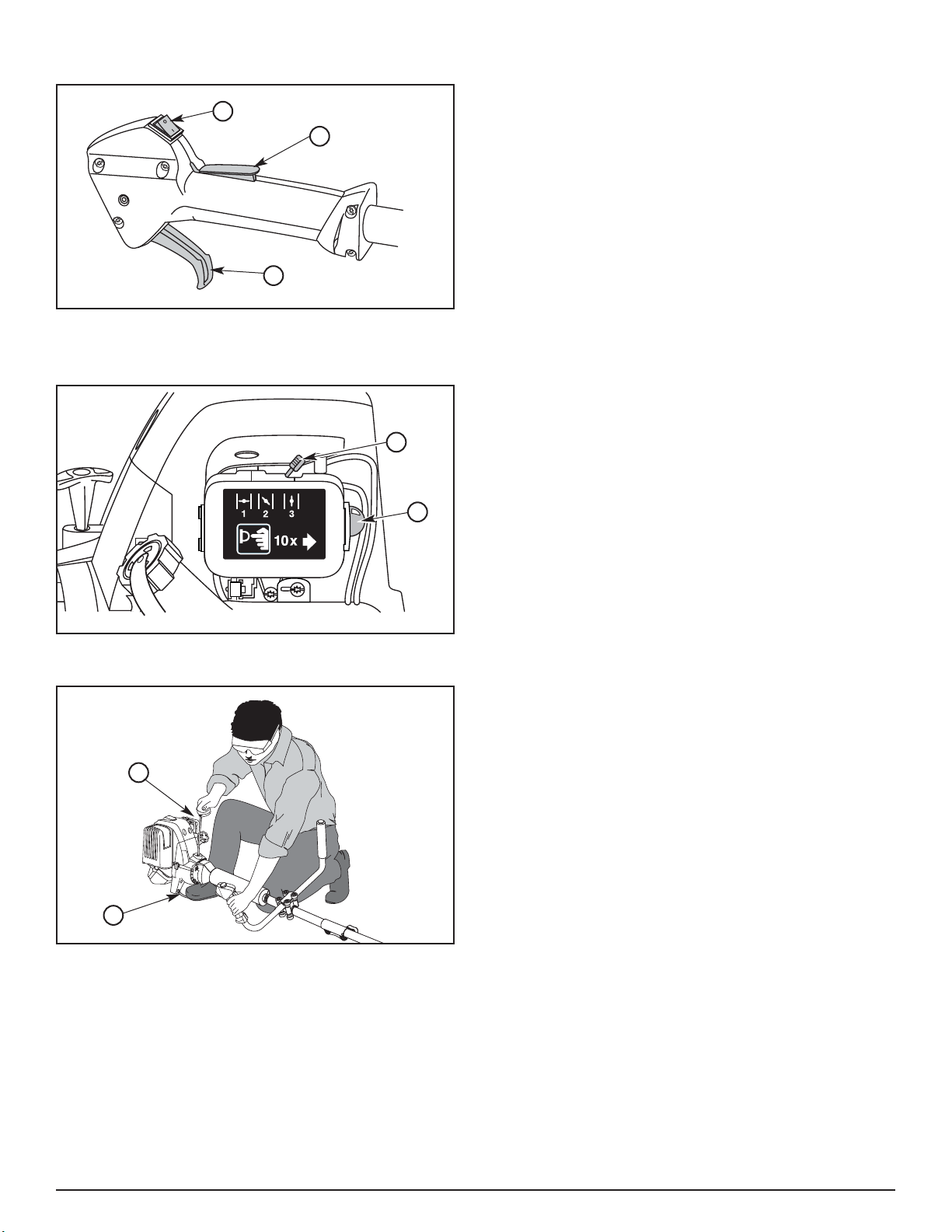
1. Cabeza motriz
2. Tapa del combustible
3. Mango de la cuerda de arranque
4. Bujía de encendido
5. Palanca del obturador
6. Cebador
7. Cubierta del filtro de aire / silenciador
8. Soporte del arnés
9. Interruptor de encendido
10. Gatillo del regulador
11. Barra de la manija
12. EZ-Link (según la versión)
13. Tubo del eje
14. Protección del accesorio de corte
15.Cuchilla limitadora de línea
16. Accesorio de corte
17. Cuchilla de corte con cubierta
18. Arnés
19. Estribo
20. Tapa del llenado de Aceite / Medidor
Beschreibung der Teile
1. Motorkopf
2. Tankverschluß
3. Starterleinengriff
4. Zündkerze
5. Chokehebel
6. Einspritzvorrichtung
7. Luftfilter/Schalldämpfer-Abdeckung
8. Schulterriemenhalterung
9. Zündschalter
10. Gashebel
11. Griffstange
12. EZ-Link (je nach Ausführung)
13. Achsenrohr
14. Schneidaufsatzabdeckung
15. Schnurschneidklinge
16. Schneidaufsatz
17. Schneidklinge mit Abdeckung
18. Schulterriemen
19. Fußstütze
20. Ölstöpsel/Ölmessstab
Descrição das peças
1. Cabeça do motor
2. Tampão do depósito de combustível
3. Pega da corda de arranque
4. Vela
5. Alavanca do estrangulador
6. Iniciador
7. Tampa do filtro de ar/silencioso
8. Apoio dos arreios
9. Interruptor da ignição
10. Gatilho do acelerador
11. Guiador
12. EZ-Link (conforme o tipo)
13. Tubo do veio
14. Resguardo do dispositivo de corte
15. Lâmina de corte do fio
16. Dispositivo de corte
17. Lâmina de corte com cobertura
18. Arreios
19. Apoio para o pé
20. Tappo del serbatoio dell’olio / Asta di livello
Descrizione dei componenti
1. Testa motore
2. Tappo serbatoio
3. Avvio a strappo
4. Candela
5. Leva starter
6. Innesco
7. Coperchio blocco filtro aria/marmitta
8. Aggancio tracolla
9. Interruttore di accensione
10. Leva acceleratore
11. Impugnatura
12. EZ-Link (secondo la versione)
13. Tubo dell’albero
14. Protezione pezzo di taglio
15. Lama falciante a filo
16. Pezzo di taglio
17. Lama falciante con copertura
18. Tracolla
19. Poggiapiede
20. Plugue de abastecimento de óleo/vareta