MOBOTIX AG
Kaiserstrasse
D-67722 Langmeil
Tel.: +49 6302 9816-103
Fax: +49 6302 9816-190
www.mobotix.com
Declaration of Conformity: www.mobotix.com > Support > MxMedia Library > Certicates
MOBOTIX, the MX logo, MxControlCenter, MxEasy, MxPEG and MxActivitySensor are trademarks of
MOBOTIX AG registered in the European Union, the U.S.A., and other countries • Information subject to
change without notice • MOBOTIX does not assume any liability for technical or editorial errors or omissions
contained herein • All rights reserved • © MOBOTIX AG 2017
Technical Specications
Product Variants Horizontal/vertical angle of illumination:
120 °, 90 °, 60 °, 45 °, 30 °, 15 °
Interfaces Ethernet (MxRJ45)
Certications
EN 55015:2013 + A1:2015
EN 61547:2009
EN 61000-4-2:2009
EN 60950-1:2006 + A11:2009/A1:2010/A12:2011
MTBF
(Mean time between
failures)
80,000 hours
Environment Sensors
(Photosensor)
When the ambient brightness drops below the
threshold of 3 lux, the illuminator switches on auto-
matically.
When the ambient brightness exceeds the 3 lux
threshold for more than 150 sec., the illuminator
switches o automatically.
Infrared Wavelength 860 nm (semi-discrete)
Power Supply Power over Ethernet IEEE 802.3at (PoE+)
Power Consumption Max. 19 W (Standby mode: 0.8 W)
Protection Class IP67
Ambient Temperature –30 to 60°C/–22 to 140°F
Dimensions/Weight H x W x D: 90 x 115 x 51 mm; weight: approx. 750 g
Important Notes
Notes on Installing
• This product must not be used in locations exposed to the dangers
of explosion.
• Make sure that you install this product as outlined in the instructions
of this Quick Install document.
• When installing this product, make sure that you are only using gen-
uine MOBOTIX parts and MOBOTIX connection cables.
• Only install this product on suitable, solid surfaces that provide for
a sturdy installation of the xing elements used.
Electrical systems and equipment may only be installed, modied and
maintained by a qualied electrician or under the direction and supervision
of a qualied electrician in accordance with the applicable electrical guide-
lines. Ensure you are using proper electrical connectors and connections.
The IR illuminatoris cooled by natural convection, so it should be installed
in such a way that the air can circulate freely around the housing.
Caution! The IR illuminator may become hot during operation.
The IR illuminator emits high-intensity infrared light. It is, therefore, danger-
ous to look into the operating device from close distances (less than 2 m)!
The IR illuminator is operated by low voltage direct current (up to 30 V DC).
It is, therefore, forbidden to connect the illuminator directly to an AC power
source.
Disposal
Electrical and electronic products contain many valuable
materials. For this reason, we recommend that you dispose of
MOBOTIX products at the end of their service life in accordance
with all legal requirements and regulations (or deposit these products at a
municipal collection center). MOBOTIX products must not be disposed of in
household waste! If the product contains a battery, please dispose of the
battery separately (the corresponding product manuals contain specic
directions if the product contains a battery).
Disclaimer
MOBOTIX AG does not assume any responsibility for damages,
which are the result of improper use or failure to comply to
the manuals or the applicable rules and regulations. Our
General Terms and Conditions apply. You can download the
current version of the General Terms and Conditions from our website at
www.mobotix.com by clicking on the COS link at the bottom of every page.
Cleaning
Clean with a damp cloth only. When an illuminator is mounted to a house
facade and you clean the wall with a high-pressure cleaner, make sure
that you do not direct the stream at the illuminator as this could damage
the illuminator.
§
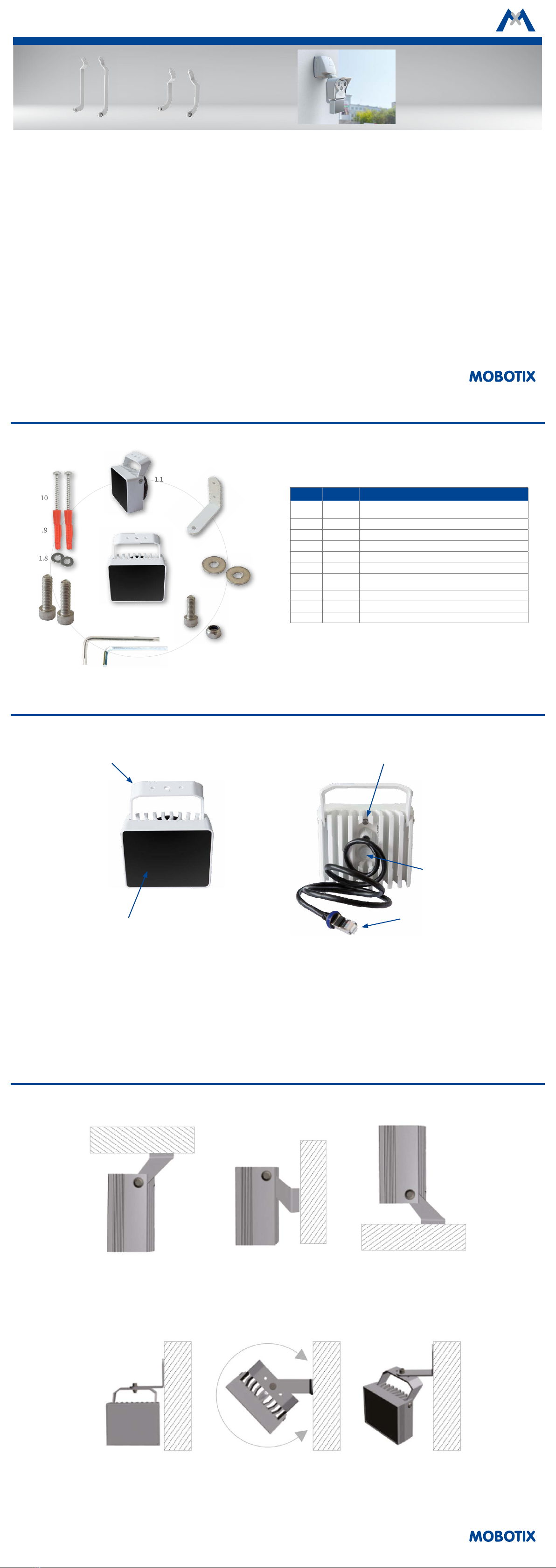
Mounting
Mounting with standard bracket
1. Draw two holes for the mounting bracket dowels at the desired loca-
tion. Drill the holes and insert the dowels (item 1.9).
2.
Loosen the screws that secure the mounting bracket to the illuminator,
so that the bracket can be moved in the desired position. Or, if neces-
sary, loosen the mounting bracket completely from the illuminator.
3. Press the mounting bracket onto the wall or ceiling so that the two
screw holes of the bracket are over the dowels. Attach the screws
(item 1.10) and the washers (item 1.8) and tighten the screws (with,
e.g., a Torx key, item 1.6).
4.
If necessary, screw the illuminator back on the mounting bracket. Adjust
the illuminator and tighten the screws to secure the mounting bracket.
Mounting with additional angle bracket (see item 1.2 "Standard Delivery")
1. Draw two holes for the angle bracket dowels at the desired location.
Drill the holes and insert the dowels (item 1.9).
2. Fasten the angle bracket with the screw (item 1.4) and the washers
(item 1.3) on the mounting bracket.
3. Press the angle bracket onto the wall or ceiling so that the two screw
holes of the bracket are above the dowels. Attach the screws (item 1.10)
and the washers (item 1.8) and tighten the screws (with, e.g., a Torx
key, item 1.6).
4. Rotate the illuminator around its vertical axis to the desired position
and tighten the screw.
5.
Loosen the screws that secure the illuminator to the mounting bracket,
adjust the illuminator and retighten the screws.
Notes on mounting
• To ensure adequate air circulation for cooling, the rear part of the illuminator must not be covered.
• Make sure that the illuminator is mounted in such a way that the photosensor at the back of the housing is neither permanently obscured and
thus darkened, nor exposed to light sources that illuminate the sensor, but not the camera surveillance area.
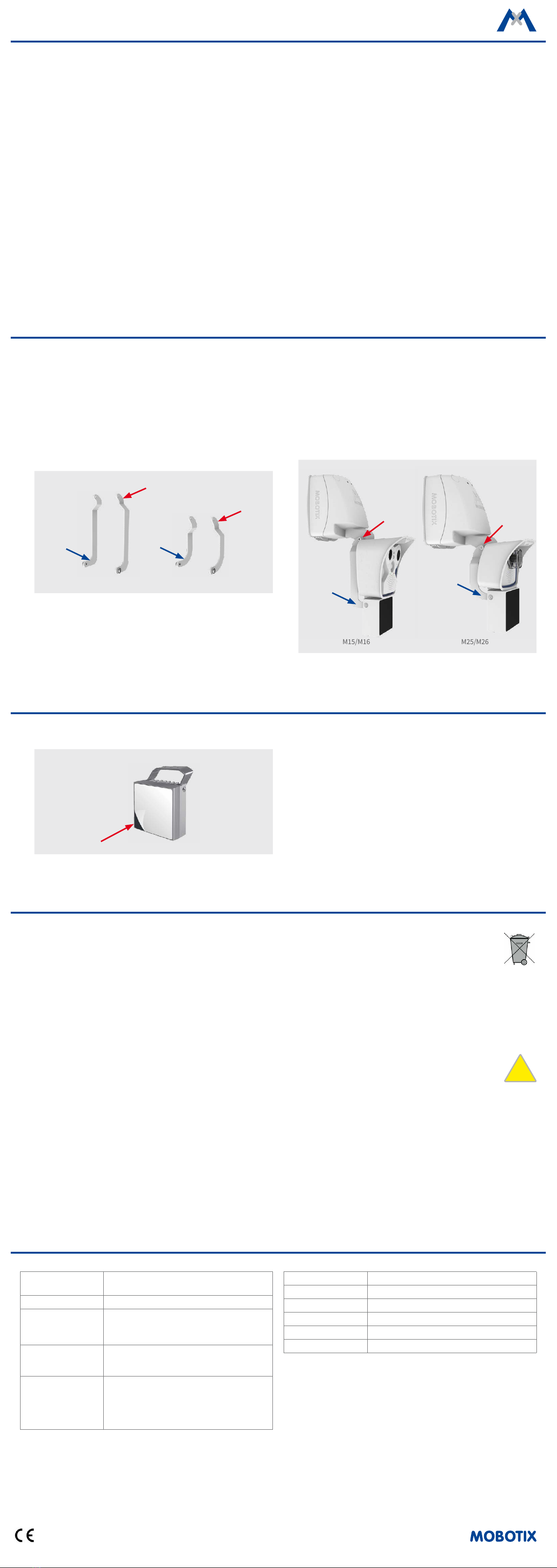
Mounting with Optional Accessories (Part No: Mx-M-IRA-ML and Part No: Mx-M-IRA-M)
As an optional accessory, MOBOTIX oers two additional sets of mounting brackets, one for AllroundDual Cameras M15/M16 (Part No: Mx-M-IRA-ML)
and the other for Allround Cameras M25/M26 (Part No: Mx-M-IRA-M). The illuminator can then be mounted to either the M15/M16 or the M25/M26 with
a weatherproof PoE connection via the MxSplitProtect. For information on mounting the camera and the MxSplitProtect, please see the
Quick Install
MxSplitProtect.
1.
Unscrew the standard bracket on the Illuminator and attach the mount-
ing bracket set for either the M15/M16 or for the M25/M26. Make sure
that the forwardly curved ends of the brackets are attached to the
illuminator (see blue arrows).
2.
Fasten the mounting brackets with the screws (item 1.7) and the wash-
ers (item 1.3, if needed) at the center joint of the wall mount of the
M15/M16 or the M25/M26 (see red arrows).
Next Steps
1. Aer mounting the illuminator, remove the protective lm from the
glass.
2. Set up the power supply by connecting the supplied network cable to
either a MxSplitProtect (please see the
Quick Install MxSplitProtect
)
or a PoE switch.
Note: In an outdoor installation without the use of an MxSplitProtect
(not recommended), one must also ensure a waterproof connection of
the RJ45 patch cable to a suitable (Cat5/Cat7) cable that leads to the
PoE switch. For this you can, for example, use a MX-Overvoltage-Pro-
tection-Box.