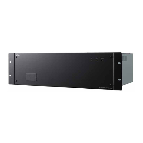
Toa SX-2000AI User manual

MATRIX SYSTEM SX-2000 SERIES
Thank you for purchasing TOA's Matrix System.
Please carefully follow the instructions in this manual to ensure long, trouble-free use of your equipment.
PLEASE READ THIS MANUAL FIRST!
1. SAFETY PRECAUTIONS ............................................................................................................... 2
2. COMPOSITION OF THE SX-2000 INSTRUCTION MANUAL ....................................................... 4
3. SYSTEM SUMMARY ...................................................................................................................... 4
4. SYSTEM FEATURES ..................................................................................................................... 5
5. SYSTEM CONFIGURATION EXAMPLES
5.1. General-purpose Broadcast ..................................................................................................... 6
5.2. Emergency/General-purpose Broadcast .................................................................................. 7
TABLE OF CONTENTS

2
1. SAFETY PRECAUTIONS
• Before installation or use, be sure to carefully read all the instructions in this section for correct and safe
operation.
• Be sure to follow all the precautionary instructions in this section, which contain important warnings and/or
cautions regarding safety.
• After reading, keep this manual handy for future reference.
When Installing the Unit
• Do not expose the unit to rain or an environment where it may be splashed by water or other liquids, as
doing so may result in fire or electric shock.
• Use the unit only with the voltage specified on the unit. Using a voltage higher than that which is specified
may result in fire or electric shock.
• (Applicable to VX-2000DS, VX-200PS, VP-2064, VP-2122, VP-2241, and VP-2421 only)
Do not cut, kink, otherwise damage nor modify the power supply cord. In addition, avoid using the power
cord in close proximity to heaters, and never place heavy objects -- including the unit itself -- on the power
cord, as doing so may result in fire or electric shock.
• (Applicable to RM-200SF, RM-200SA, RM-210, and RM-200RJ only)
Avoid installing or mounting the unit in unstable locations, such as on a rickety table or a slanted surface.
Doing so may result in the unit falling down and causing personal injury and/or property damage.
• (Applicable to RM-200SF, RM-200SA, RM-210, and RM-200RJ only)
Install the unit only in a location that can structurally support the weight of the unit and the mounting bracket.
Doing otherwise may result in the unit falling down and causing personal injury and/or property damage.
• Since the unit is designed for in-door use, do not install it outdoors. If installed outdoors, the aging of parts
causes the unit to fall off, resulting in personal injury. Also, when it gets wet with rain, there is a danger of
electric shock.
When the Unit is in Use
• Should the following irregularity be found during use, immediately switch off the main power (or circuit
breaker), and contact your nearest TOA dealer. Make no further attempt to operate the unit in this condition
as this may cause fire or electric shock.
· If you detect smoke or a strange smell coming from the unit.
· If water or any metallic object gets into the unit
· If the unit falls, or the unit case breaks
· (Applicable to VX-2000DS and VX-200PS only)
If the power supply cord is damaged (exposure of the core, disconnection, etc.)
· If it is malfunctioning (no tone sounds.)
• To prevent a fire or electric shock, never open the unit case nor modify the unit. Refer all servicing to
qualified service personnel.
• Do not place cups, bowls, or other containers of liquid or metallic objects on top of the unit. If they
accidentally spill into the unit, this may cause a fire or electric shock.
• (Applicable to VX-2000DS, VX-200PS, VP-2064, VP-2122, VP-2241, and VP-2421 only)
Do not insert nor drop metallic objects or flammable materials in the ventilation slots of the unit's cover as
this may result in fire or electric shock.
• (Applicable to VX-2000DS and VX-200PS only)
Do not touch a power supply plug during thunder and lightning, as this may result in electric shock.
• (Applicable to VX-200PS only)
When replacing the fuse, be sure to use the supplied one (3.15 A). Using any other fuse than supplied may
cause fire or electric shock.
Indicates a potentially hazardous situation which, if mishandled, could
result in death or serious personal injury.
WARNING
3
When Installing the Unit
• (Applicable to VX-2000DS and VX-200PS only)
Never plug in nor remove the power supply plug with wet hands, as doing so may cause electric shock.
• (Applicable to VX-2000DS and VX-200PS only)
When unplugging the power supply cord, be sure to grasp the power supply plug; never pull on the cord
itself. Operating the unit with a damaged power supply cord may cause a fire or electric shock.
• (Applicable to VX-2000DS, VX-200PS, VP-2064, VP-2122, VP-2241, and VP-2421 only)
Do not block the ventilation slots in the unit's cover. Doing so may cause heat to build up inside the unit and
result in fire.
•
Avoid installing the unit in humid or dusty locations, in locations exposed to the direct sunlight, near the heaters,
or in locations generating sooty smoke or steam as doing otherwise may result in fire or electric shock.
• Note correct polarity (positive and negative orientation) when connecting the power supply cord. Reversed
polarity connections will cause damage to the amplifier.
• System units (except remote microphones) are designed exclusively to be mounted in an equipment rack.
Be sure to observe the following instructions when rack-mounting the unit. Failure to do so may cause a fire
or personal injury.
· Install the equipment rack on a stable, hard floor. Fix it with anchor bolts or take other arrangements to
prevent it from falling down.
· When connecting the power cord of the DC power supply panel for the units to an AC outlet, ensure that
the total load current never exceeds the AC outlet's allowable current capacity.
· The supplied rack-mounting screws can be used for the TOA equipment rack only. Do not use them for
other racks.
• (Applicable to VX-2000DS only)
Note correct polarity (positive and negative orientation) when connecting the power supply cord. Reversed
polarity connections will cause damage to the system.
When the Unit is in Use
• (Applicable to VP-2064, VP-2122, VP-2241, and VP-2421 only)
Do not operate the unit for an extended period of time with the sound distorting. This is an indication of a
malfunction, which in turn can cause heat to generate and result in a fire.
• Use the specified power supply unit for the system. Note that the use of other power supply unit may cause
a fire.
• (Applicable to VX-2000DS only)
Make sure to observe the following handling precautions so that a fire or personal injury does not result from
leakage or explosion of the battery.
· Do not short, disassemble, heat nor put the battery into a fire.
· Avoid using both new and old batteries together.
· Never charge batteries of the type which are not rechargeable.
· Do not solder a battery directly.
· Be sure to use the specified type of batteries.
· Note correct polarity (positive and negative orientation) when connecting a battery to the unit.
· Avoid locations exposed to the direct sunlight, high temperature and high humidity when storing batteries.
• (Applicable to RM-200SF and RM-200SA only)
Have the unit checked periodically by the shop from where it was purchased. Failure to do so may result in
corrosion or damage to the unit or its mounting bracket that could cause the unit to fall, possibly causing
personal injury.
• (Applicable to VX-200PS only)
Contact your TOA dealer as to the cleaning. If dust is allowed to accumulate in the unit over a long period of
time, a fire or damage to the unit may result.
Indicates a potentially hazardous situation which, if mishandled, could
result in moderate or minor personal injury, and/or property damage.
CAUTION

4
3. SYSTEM SUMMARY
TOA's SX-2000 series Matrix systems are input and output signal routing processing systems that function as
the core for multi-channel general-purpose broadcast systems, and are designed for use in such locations as
shopping centers, department stores and shop/store complexes. The SX-2000 systems are designed to
distribute remote microphone outputs, automatic guidance broadcasts, background music, and sounds from
other connected sources to power amplifiers via an audio signal/control signal matrix with 16 digital busses
using pre-determined conditions and priorities.
The SX-2000 system allows 3 types of broadcasts to be made: General-purpose broadcast such as general
paging and BGM, Emergency broadcast that the emergency messages are to be broadcast by an automatic
announcement device or remote microphone, and General urgency all-call broadcast* that is to be made
available even during system malfunctions or failures.
The dedicated software is used to perform all necessary settings related to the entire system operation and
functions including system configurations, input-to-output signal routing, function assignment to the operation
keys, operation of the control terminals, and selection of the failure detection points.
* Available when an analog link is connected.
2. COMPOSITION OF THE SX-2000 INSTRUCTION MANUAL
The SX-2000 system Instruction manual is divided into 4 parts.
Please read the proper manual for your purpose.
This manual
(PLEASE READ THIS MANUAL FIRST)
For broadcast management and setup
For broadcasting operation
Separate Manual
(Print and CD)
Separate Manual
(CD only)
Operating Instructions
For unit installation
Setting Software Instructions
Installation Manual

5
4. SYSTEM FEATURES
• Emergency broadcasts can be implemented by using the settings made among 32 EV messages, 4
Emergency Sequences, and 128 Emergency Broadcast Patterns.
• Using the dedicated software program, functions such as broadcast start conditions, broadcast channels
(input sound source signal routing), and broadcast priorities can be set with no need to change equipment
connections.
• Surveillance function that continuously monitors such status at the major points from input to output of the
system as each unit operation, cable connections or communications between the units, and power supply,
and that alerts the operator by indicators, buzzer, or contact outputs in the event of operation error or
equipment malfunctions.
• Backup batteries assure the system operation during power failures.
• Local audio inputs are provided for the SX-2100AO, enabling local broadcast to be made from each SX-
2100AO.
• General urgency broadcasts can be made even during system malfunctions or failures (when Analog Link
connection is made).
• System equipment operation logs and failure logs are recorded on a CF card and can be confirmed on a PC
screen.
• Input and output equipment, such as broadcasting sound sources (including remote microphones and BGM
players) and amplifiers can be combined, depending on their types and quantities, for most appropriate
system configuration. The system can be designed for a minimum configuration of 2 inputs and 8 outputs,
expandable up to 64-input/256-output*1configuration in units of 2 inputs or 8 outputs.
*1When the system is configured with 1 SX-2000SM, 8 SX-2000AIs or SX-2100AIs, and 32 SX-2000AOs or
SX-2100AOs.
• Up to 16 channels of broadcasts can be simultaneously made.
(Up to 8 channels of EV messages can be simultaneously broadcast.)
• One each of SX-2000CI with 32 control input channels and SX-2000CO with 32 control output channels can
be connected to the SX-2000AO or SX-2100AO.
• Up to 64 RM-200SF Fireman's Microphones or RM-200SA Remote Microphones (Up to 8 units per SX-
2000AI or SX-2100AI) can be connected. Up to 5 RM-210 Remote Microphone Extension units can be
connected per RM-200SF, and up to 4 RM-210 units per RM-200SA.
• Control inputs and outputs permit broadcasts to be started by external equipment or external equipment to
be controlled when broadcasts are started. Control inputs and outputs can be expanded from 16 inputs and
outputs (minimum) to up to 1416 inputs and outputs*2depending on the system scale.
*2When the system is configured with 1 SX-2000SM, 8 SX-2100AIs, 32 SX-2000AOs or SX-2100AOs, 32
SX-2000CIs, and 32 SX-2000COs.
• SX-2000 system’s operation statuses and logs can be confirmed by establishing an online connection
between the SX-2000SM and PC.
• Input level indicators, output level indicators and monitor speakers are provided for input and output signal
monitoring.
• Key lock function prevents mistaken operation of front panel keys.
• Dual power system prevents the system from crashing if the power supply line is broken or power supply
unit fails.

6
5. SYSTEM CONFIGURATION EXAMPLES
5.1. General-purpose Broadcast
Control input unit
SX-2000CI
CI/CO
link CI/CO
link
Control output unit
SX-2000CO
A
A
RM-200RJ
Remote microphone
RM-200SA
RM-200SA
RM-200SA
Remote microphone interface module
SX-200RM
Remote microphone interface module
SX-200RM
Microphone/Line input module
D-922E
Stereo input module
D-936R
System manager
SX-2000SM
Audio input unit SX-2100AI
or SX-2000AI
Audio output unit
SX-2000AO
24 V DC
24 V DC24 V DC
24 V DC 24 V DC
Analog link
Analog link
Zone 1
12 8
Zone 2
Zone 8
SX link
(A, B 2 lines)
SX link
(A, B 2 lines)
SX link (A, B 2 lines)
Contact control
Contact control Contact control
Contact control (when using the SX-2100AI)
DC power supply unit
DC power
supply unit
DC power
supply unit
Power amplifier
Power amplifier
Power amplifier
Chime
Programmable timer
BGM 1
BGM 2
SW-HUB CF card
(Setting/Log data)
Digital announcer
Programmable timer

7
5.2. Emergency/General-purpose Broadcast
Control input unit
SX-2000CI
Control output unit
SX-2000CO
A
B
B
C
C
D
D
E
E
A
RM-200RJ
RM-200SA
Remote microphone interface module
SX-200RM
Remote microphone interface module
SX-200RM
Microphone/Line input module
D-922E
Stereo input module
D-936R
System manager
SX-2000SM
Audio input unit SX-2100AI
or SX-2000AI
Audio output unit
SX-2100AO
24 V DC
24 V DC
24 V DC
24 V DC 24 V DC
Analog link
Analog link
Zone 1
12 8
Zone 2
Zone 8
SX link
(A, B 2 lines)
SX link
(A, B 2 lines)
SX link (A, B 2 lines)
CI/CO
link CI/CO
link
Contact
control Contact control Contact control
Contact control (when using the SX-2100AI)
Emergency power supply
VX-2000DS
Power amplifier
Power amplifier
Battery VX-200PS
Power amplifier
Standby amplifier
Standby
amplifier
Chime
Programmable timer
BGM 1
BGM 2
SW-HUB CF card
(Setting/Log data)
Digital announcer
Fireman’s microphone
RM-200SF
Remote microphone
RM-200SA
Programmable timer

Traceability Information for Europe
Manufacturer:
TOA Corporation
7-2-1, Minatojima-Nakamachi, Chuo-ku, Kobe, Hyogo,
Japan
Authorized representative:
TOA Electronics Europe GmbH
Suederstrasse 282, 20537 Hamburg,
Germany
URL: http://www.toa.jp/
133-02-00320-00
Warning
This equipment is compliant with Class A of CISPR 32. In a residential environment this equipment may
cause radio interference.
This manual suits for next models
4
Table of contents
Other Toa Security System manuals

Toa
Toa RS-150 User manual

Toa
Toa VX-2000 Series User manual

Toa
Toa VX-2000 Series Guide

Toa
Toa VX-3308WM User manual

Toa
Toa VX-3000 SERIES User manual

Toa
Toa Netcansee N-VR2010 User manual

Toa
Toa VS-900 User manual

Toa
Toa ALARM INPUT UNIT C-AL80(H) User manual

Toa
Toa VM-3000 Series User manual

Toa
Toa VM-3000 Series User manual