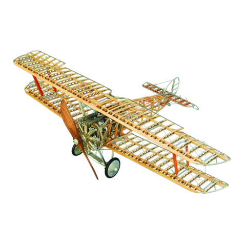
Model Airways Fokker Eindecker E-IV User manual

1

2
Before You Begin to Build
At 1:16 scale, it is easy to build this Fokker Eindecker E-IV model and obtain precise detail. Laser cut
parts offer a simple building method. Britannia (white metal) parts eliminate creating metal parts from
scratch. However; some metal fittings will need to be formed using brass tube for authentic detailing.
Before starting to assemble the model, carefully examine the kit and study the Plan Sheets and the
Assembly Instruction Manual. First, determine if all the listed kit parts are present using the Plan
Parts Layout Sheet; Materials List and Assembly Instructions. Handling the parts will provide a
better understanding of the kit’s building requirements. Try to visualize how every part will look on the
completed model. Also, try to follow the building sequence and what must be completed first, or ahead
of time and what can be done simultaneously if you wish. For example, you may want to skip to the
Propeller as you are working on the Fuselage waiting for glued assemblies to set or paint to dry.
The Plans: Four (4) Plan Sheets are provided for reference and part identification and may not be
exactly true to scale due to the reproduction process. These drawings show elevation views, a parts
layout with color guide and laser cut layout sheets. Review and study the plans and assembly
instructions prior to starting the build to better understand how the parts will come together and the
proper build sequence.
Make Allowances: Try to be exact when following the instructions, but use common sense.
Adjustments may be necessary to compensate for small differences in how your model is shaping up
and how the parts are relating to each other. An old saying in the model building craft is that “if it looks
right, it is right.” Also check the instruction photographs for various details before working on them.
Kit Lumber: Laser cut Plywood and Basswood parts are supplied in the kit. A word about laser cutting:
a common misconception is that the parts should punch out of the carrier sheet. This is not so. Laser
cut parts are retained in the carrier sheet by small bridges of uncut wood called tabs. Tabs can be
oriented parallel to the wood grain or perpendicular to the wood grain. It is always better to cut through
these tabs rather than try to punch out the parts by breaking the tabs. You may have to cut through not
only the tabs but portions of the part outline that did not cut completely through the sheet. Turn the
carrier sheet over and cut from the backside to release the part without damage. Care must be taken
when cutting out parts due to the thickness of plywood which in some cases is very thin to maintain
proper scale.
Laser cut parts: There are plywood laser cut parts and laser cutting burns through the plywood leaving
charred surfaces. The charred surface sometimes does not make good strong glue joints. It is
recommended to sand or scrape away the loose char before gluing. It is not necessary to remove all
the char, unless a finished wood surface is required. In some cases simply scraping with the back edge
of a # 11 blade is sufficient. The use of a small sanding drum in a rotary tool with a light touch would
work best on the thicker plywood edges.
Britannia Metal Parts: There are many Britannia (white metal) parts in this kit. First, remove any mold
joint flash with a #11 hobby blade using the back edge as a scraper, then file or sand with fine sanding
stick or sandpaper. Important: Always dry fit parts together first to determine if holes need to be
drilled further or if mating surfaces are flat to each other. Once parts have been dry fitted wash

3
parts in dishwashing liquid and warm water to remove traces of mold release agent and body oils your
fingers may deposit. Allow the parts to dry thoroughly before applying primer and painting. Try to avoid
painting, whenever possible, surfaces to be glued together, or locating pins that insert into holes. Due
to the metal casting process used and shipping; some deformed parts may be received, or filled in
holes that will have to be drilled. Parts can be straightened by gently and slowly reforming with your
fingers. Check with the plans and photographs to verify the reforming of the part(s); every effort was
made to reproduce the parts accurately but some deforming may occur during de-molding or shipping
due to the weight of the parts themselves.
Photo Etched Parts: An etched aluminum sheet of parts is included in the kit. Care must be used to
cut these parts from the carrier sheet using the tip of a hobby knife blade on a hard surface like steel or
use small scissors/snips. Cut tabs will need to be filed smooth using a fine needle file. The “Eindecker
E-IV” on the aluminum sheet can be used to make a nameplate if desired.
Glues: Super glues, such as Jet, Flash, or Zap, produce quick adhesion. For most applications, the
medium viscosity, gap-filling variety is best allowing a little time for final positioning. The thin type is
recommended for filling a narrow crack, wicking into laminated tight joints and seizing thread ends to
make “needle” points. These instructions will refer to super glues as CA (cyanoacrylite). For Basswood
and Plywood it is best to use Yellow Wood glue like Titebond which is easier to sand than CA which
hardens the plywood. Epoxy glue is highly recommended for gluing metal cast engine parts some of
which are heavy. The five minute setting type is sufficient for this build. Scoring mating metal joint
surfaces with the tip of a hobby knife in a cross hatch pattern will increase the strength of the glue
joints. Excess glue can be cleaned carefully with acetone on a Q-tip, but take care not to loosen the
glued joint.
Building Tips and Suggestions before Starting to Build
Read assembly instructions, study the pictures and review the plans to understand and familiarize
yourself with various parts and components and how they relate to each other.
Check parts list to make sure you have all the kit parts listed.
Verify that you have all the tools and materials needed to start the build. See the materials list and
suggested tool list on the next page. A variety of rubber bands is essential to assemble the fuselage.
Try to follow the suggested build sequence outlined in the assembly instructions.
Pay attention to steps that are BOLD face type or underlined. These are critical actions to avoid
problems with assembly or when extra care is needed. Parts are Capitalized and Boldface on purpose
for emphasis and identification when reading and easy reference. Cast white metal parts in some cases
are delicate due to replicating in scale. Extra care and caution is required when cleaning, filing parting
lines and adjusting to dry fit.
Prime, paint and dry fit all cast parts prior to assembling. Keep primer and paint to a minimum to retain
fine details. When dry fitting parts if excess paint is an issue scrap off paint as needed for a good fit.
Keep in mind it is better to have two or three light coats rather than one thick coat of paint. Fill casting
voids with putty if required and then sand and prime before painting.
Take your time, learn and enjoy the build process as much as the finished model.
Building Strategy: Due to the number of laser cut parts in the kit for the wings; it is recommended to
clean, file, dry fit then paint the wood once the wings are assembled.

4
The following instructions will address some sub-assemblies of components to be worked on and then
set aside for later assembly.
Paint all the cast metal parts first before starting to assemble. Paint brass components once assembled
to painted parts to match during the build process.
Additional materials that will be needed:
Medium CA –Small Bottle
Thin CA –Small Bottle
1 small bottle of Yellow Glue.
1 small bottle of White Glue.
Fine sand paper or sanding sticks.
1 Bottle MS 4821 Deck House Light
1 Bottle MS4962 Aluminum
1 Bottle MS 4970 Copper
1 Bottle MS 4839 Primer
1 Bottle MS4973 Pre-stain Wood Conditioner
1 Bottle MS 4823 Pearl Gray
1 Bottle MS 4802 Gun Carriage Red
1 Bottle MS 4830 Hull Spar Black
1 Bottle MS 4975 English Oak
1 Bottle MS 4961 Brass
1 Bottle MS 4972 Clear Satin
#2 and #7 Round paint brushes.
10/0 spotter paint brush for touch up.
1/2” Flat brush (for cleaning and
dusting)
Small can of Acetone–clean/ debond
glue.
Small pins/ T-pins
A variety of flat rubber bands.
Suggested tool list:
Hobby knife blade holder.
#11 blades - 12- 18 as needed. 1 chisel blade.
Hobby Knife Saw Blade
Small needle nose pliers.
Small end cutters.
Tweezers –straight and bent.
Medium size Mill Bastard file.
Needle files. Flat , Half Round, and Square
ScotchBrite pad- Fine and Medium.
Sanding paper/stick –80,100,120,220 grits.
Set of small reams to clean holes.
Small Square.
Several round toothpicks.
Round flat drift punch.
Wax paper.
Masking tape- automotive low tack
Drill Bits 1/32”; 3/64”;1/16”; 1/4:”
Pin vise for drill bits.
X –Y table for drill press.
Mechanical Pencil .05 lead sizes.
Small 4” bar clamps –2 to 4
Metal spring clamps - 10 to 12
Small Plastic clamps –10 to 12
Small package of Clothes pins.
1 Stainless steel pick –bent ends.
The Materials List identifying the parts supplied in the kit is a separate document to this manual. Use
plan sheet “Parts Layout and Color Guide” to check for parts as well as the colors to paint them.
Parts: The very first step is to paint all the cast metal parts their respective colors using the Color
Guide Plan Sheet. This will help to better understand the parts and how they relate to each other; do

5
any adjustments that are needed and remember to bend very slowly to relieve any stress in the parts
and avoid breaking the part. It will also enable an inventory to make sure that there are no missing
parts. For this instruction manual all parts were painted using Model Expo paints and brush painted.
Some builders may prefer other brands and spaying with airbrush rather than by hand.
Instruments:
Carefully cut out the printed instrument faces and glue them in place to the correct painted cast metal
instrument bezels. Note that the two “Axial” labels will go on the propeller once it is carved. Extra
detail: Mix some 5 epoxy and add to the instrument face while level, this must be done quickly before
the epoxy starts to set. Better to do in two groups of bezels and this will form lenses for the instruments.
There is a detailed explanation further on in these instructions to do the Instrument Lenses read
ahead to locate. Building all the Instruments ahead of time is recommended and will assure ample
drying time for the epoxy lenses to set before handling. See the pictures below.
Fuselage Building Fixture:
Remove the 1/8” plywood parts required to assemble the Fuselage Building Fixture; laser cut parts
sheets “H” and “I” and clean the char from all the edges. A suggestion is to paint the edges with Wood
Conditioner to stabilize the char from transfer while handling the fixture during the build assembly.
Next using the 1/16” x 3/16” x5” wood strip cut five (5) spacers 3/4” long and glue them to the Stations
in places marked “Spacer” making sure the top edges of the spacers align with the top of the laser cut
lines on the Stations. This alignment of the spacers is critical.
Once the Stations are ready, assemble the Building Fixture indexing the Stations in proper marked
sequence to each other. Note do not glue the Station parts 2 to 7 in place and note that the Building
Fixture does taper narrowing from rear to front. See picture on the next page to the left with assembled
parts. With the Stations in place, insert the 1/8” diameter x11” Brass Tube down the center through
the holes in the Stations to stabilize the Building Fixture. This will help greatly when handling during
assembly.

6
Turnbuckles:
There are many Turnbuckles to be used for this build. Each Turnbuckle should be cleaned; holes
drilled with 1/32” (#67) drill bit if necessary then primed and painted Brass. Using a needle threader
insert it into a Turnbuckle hole then index a thread loop into the threader and pull the loop back
through the Turnbuckle hole just to clear the hole. Now with tweezers inserted through the loop pull
the two ends of the thread back through the loop and seize the Turnbuckle pulling the ends to tighten;
once tight on the Turnbuckle tie a half hitch and add a drop of thin CA on the short thread end and pull
the long thread to have the glue set straight. When the glue has set cut off the short end at the knot.
Repeat the process on the other end of the Turnbuckle. Tie enough Turnbuckles for each section of
the build as needed. Tip: On the needle threader crimp tighter the junction of the wire with the
aluminum handle using pliers to help eliminate the wire being pulled out of the handle.
Fuselage:
Now locate the nine (9) cast parts and three (3) brass tubes needed to assemble the cockpit area of the
Fuselage. The cast parts are the Cockpit Area Side Frames (2 - Left and right); upper rear Seat
Cross Frame; Landing Gear Bracket; lower Rear Pivot Brace; forward upper and lower Fuselage
Attachment Cross Members (2); Tachometer; Hand Pump. The following Brass tubes: Wing Spar
Braces (2) 3/32” x 1- 9/16”; Lower Center Cross Frame (1) 1/16” x 1- 21/32”.

7
Tie the ten (10) Turnbuckles to the Side Frames as seen in the picture below. Note that all
Turnbuckles are in the upper and lower corners towards the front of the plane. This will also apply to
all the fuselage stations as well. Now glue the painted Hand Pump to the right Side Frame at the two
(2) location holes for the pins on the Hand Pump. The Tachometer can also be glued in place on the
left Side Frame in the location hole with a slight angle up.
TIP: Locate the painted Black Joystick Control Rod and Rear Pivot Brace and test fit the Rod shaft
into the center hole in the Brace; the Rod shaft must be able to move freely through the hole when
painted. If it does not ream/enlarge the hole until it does; this is much easier to do now than later.
Add the two painted (2) Wing Spar Braces to the pins on the inside of the Wing Spar Boxes. Dry fit
the Braces first with the Side Frames on a flat surface and square to the Side Frames. Now carefully
insert the assembly into the Building Fixture and hold together with rubber bands as seen in the
picture above. Now dry fit the following parts by carefully indexing them into their locations working from
the center out. First the Lower Center Frame; Landing Gear Bracket; Seat Cross Frame; Rear Pivot
Brace; upper Attachment Cross Member and finally the lower Attachment Cross Member which
indexes into the Landing Gear Bracket as seen in the picture below. Note that some parts may need
adjustment or straightening to fit properly. Once all parts are dry fitted and held in place with rubber
bands; then square up the assembly and glue all connections using ample thin CA and allow the
assembly glue joints to set, about an hour or longer should work. Start with gluing the Wing Braces
first to set the assembly square; then the rest of the joints.

8
While waiting for the assembly glue to set; file the corner shoulders of the five (5) fuselage Stations (3
to 7) flush to the frame structures on both sides for a more authentic detail. See picture on the previous
page. Due to metal casting limitations it was necessary to add the shoulders to assure proper filling of
the corners. Once filed smooth to match the frame, touch up the paint.
Now rig the five (5) Fuselage Stations with Turnbuckles and try to equalize the Turnbuckles from the
two corners as seen in the picture below.
Using rubber bands add the five (5) Stations (3 to 7) to the front side of the Building Fixture locations
making sure the Stations are centered and resting level on the Spacers. The rubber bands must hold
the Stations tightly in place. See the picture above.
Now glue in place the four (4) 3/32” x 3/4” brass tube Fuselage Joiners to the rear ends of the Side
Frames making sure they are completely seated against the Side Frames. These joints are per the
original design.
Add the Rudder Pivot cast metal part to the rear end of the Building Fixture indexing it onto the
quarter rounds and hold it in place using a rubber band as seen in the picture on the next page. The
Rudder Pivot must be centered and plumb vertically. The Rudder will index through the hole so it can
be inserted to check.
Next, dry fit the four (4) brass tube Fuselage Stringers 1/16” x 10- 3/4” inserting them one at a time
starting with the bottom two (2) and then the top two (2) into the Fuselage Joiners, onto all the Station
corners and finally the Rudder Pivot. Carefully bend the Fuselage Stringers to relieve any stress and
ideally the Fuselage Stringers should be able to rest in place between the Fuselage Joiners and the
Rudder Pivot. See the pictures on the next page.

9
Next using binding wire, seize the Fuselage Stringers in place in front of each Station diagonally
twisting the wire to tighten in place on the Station corners. Start at the rear and move forward as seen
in the picture below. Once all the Fuselage Stringers are seized and adjusted check the Rudder Pivot
to be on center and vertically plumb then glue all the joints and allow the glue to set completely. See
picture below.
Once the glue has set completely on all the stringer joints slowly remove the 1/8” brass tube Stabilizer
from the Stations and then the two (2) sides of the Building Fixture down from the wood Stations.
See the picture on the next page. Next cut all the Station rubber bands and carefully remove the
Stations by turning them diagonally and down leaving only the Fuselage with the binding wires still in
place for now. Check all joints to make sure they are tight and still glued securely. If in doubt glue the
joints again.

10
Now with the binding wires still in place cut away the extended support from the Rudder Pivot using a
jeweler’s saw and file and sand smooth the saw cuts to match the contour of the Fuselage frame
structure as seen in the picture below. These extensions were cast in place to facilitate correct
alignment of the Fuselage when building.
Now cut away and remove the binding wires with small snips taking care not to snag the Stringers.
Add the rigged turnbuckles to all the Fuselage sides, tops and bottoms starting at the rear and up to
Station 3. The bay between 3 and 2 must be left open to add the Main Gas Tank. See picture above
and on the next page

11
Glue the right side Frame Member in place with the three joints being tight. The ends of the Frame
Member can be filed half round with a small round file to match the Stringers.
Assemble the Main Gas Tank and paint it Brass if not already done, or touch up when assembled. The
two (2) halves of the Main gas Tank index to each other, medium CA can be added to the mating
surfaces and the Medium CA allows a few seconds for part alignment before setting. Once the Main
Gas Tank is ready to install insert it into the bay from the left side and index the front support into the
notches in the Frames (left and right) and glue in place holding horizontal with the top aligned with the
top of the Stringers until the glue sets.
Add the Cables with Turnbuckles from the Main Gas tank to the four (4) frame loops in the upper and
lower corners of the bay as seen in the picture above. Now glue in place the two (2) cast metal Upper
Tank Straps and Lower Tank Straps between the outer edges and the ring in the Tank. Now add the
left side Frame Member in place just like the right side. Finally, rig the cables with Turnbuckles to all
sides of the bay of the Fuselage. See the picture above. NOTE: Other Main Tank details can be added
later once the Landing Gear is in place.

12
Dry fit and adjust as necessary the Tail Skid Frame to the Fuselage with the front leg of the Tail Skid
Frame indexed on the Stringer joint at Station #7 and the front edge of the rear leg of the Tail Skid
Frame 1/2” from the end of the Fuselage. Check the plans to verify the location. Use a 3/32” x 2 -7/8””
brass rod (for landing gear) to align the Tail Skid Frame on center and plumb vertically. This alignment
is important so that the Rudder will be vertical and centered. Once satisfied with adjustment and fit glue
the Tail Skid Frame in place with the 3/32” x 2-7/8” brass rod in place to check for alignment needed.
See the picture above.
Locate the Photo Etched Sheet of parts and carefully remove the Wind Baffle part by cutting the
connecting tabs. Mix the white primer with a touch of English Oak to have an off White color replicating
the look of canvas. The primer mix will result in a matte finish. Paint both sides of the Wind Baffle
thinning the primer mix with water for a smooth finish as seen in the pictures below. If the perimeter
holes are filled with paint use a pin to open the hole. Once dry, insert the Wind Baffle into the
Fuselage at station #2 forward of the Main Gas Tank. Use the gray thread to align and hold the top
center in place against the curved frame member using the top five (5) holes. See picture below. Now
using the Black thread lash the Wind Baffle in place and starting at the right side center bottom lash
around the Frames holding the Wind Baffle in place to the Frames. Add thin CA to the end of the
Black thread and cut at an angle to form a needle like end; this will help in threading through the holes.
When completely around to the bottom left center then seize the end of the thread with glue and trim off
the excess.

13
Locate the following parts: Cowl Frame, Left anf Right Crankshaft Support Arms, Crankshaft,
Carburator Adjustment Handle and four (4) 0-80 Nuts. These parts may need signifcant adjusting to
fit each other so adjust any bending very slowly. The Right Crankshaft Support Arm has the longer
bolt studs than the left one when fitting them into the four holes at the end of the Fuselage Frame.
Using a 1/32” drill bit ream/drill out the top and bottom holes on the Crankshaft adjcent to the locator
pins and on center left and right sides. See engine detail on plan sheet for hole locations. Glue the the
Carburator Adjustment Handle into the top hole. Carefully thread loosely the four 0-80 nuts onto the
bolt studs enough for a snug fit but still slightly loose. This will allow for moving. Now, from within the
cockpit add the Crankshaft indexing the two pins on the Crankshaft into the holes on the Crankshaft
Support Arms and through the center hole in the Cowl Frame with the Carburator Adjustment
Handle up as seen on the plan sheet. Bending and fitting the Crankshaft Support Arms may be
required and the Crankshaft needs to be centered left to right and up and down best as possible. This
is critical for the proper alignment of the Engine. Once the proper fit is attained tighten the four (4) 0-80
Nuts for a snug fit. DO NOT OVER TIGHTEN this will break off the bolt stud. If broken save broken
stud with nut to be glued later.
Now remove the Firewall from the Photo Etched Sheet and brush both sides hoizontally with a
Scothbrite pad or fine sandpaper for a natural brushed aluminum finish. Next bend the two sides 90
degrees on the half etched lines and the bottom about 20 degrees from centerline to match the lower
Fuselage Frame. Remove the four 0-80 nuts and the Cowl Frame and fit the Firewall on bolt studs,
now replace the Cowl Frame in place and with a pencil, mark a cut line on the Firewall with the top
edge of the Cowl Frame as a guide. See picture on the next page.Then remove both and cut along the
trim line on the Firewall and carefully lightly sand the cut edge smooth. Now replace both back in place
and add the four 0-80 Nuts for a snug fit. DO NOT OVER TIGHTEN! Note the large center hole in the
Firewall should index around the center Crankshaft support on the Cowl Frame as seen in the picture
on the next page.

14
Insert the Interrupter Holder into the hole just above the Crankshaft hole as seen in the picture
above. Then the Interrupter Linkage Pivot into the location hole at the top of the Cowl Frame. Cut
and bend two (2) 1/32” brass rods indexed into Pivot Levers and Interrupter Holder holes and
linkage. The two linkage rods are painted Black
Locate the two (2) Landing Gear Swing Arms, two (2) 00-90 x 1/4” Bolts and two 00-90 Nuts. The
Swing Arms on one end have an extended portion with a hole for a mounting bolt; this portion should
be in the down position as seen in the picture above. Insert the extended portion into the rectangular
openings formed by the two Frame members below the forward Wing Socket. Index the other end into
the hole located in the Frame Center Brace aligning the holes; then insert a 00-90 x 1/4” Bolt from the
rear side into the aligned holes and then add the Nut and tighten enough to allow the arm to move up
and down. Repeat the procedure for the other arm and both arms should be able to move up and down
within the rectangular openings. If a nut driver or wrench is not available drill a hole sized just enough to
press fit a bolt head into the end of a 1/8” dowel long enough to fit through the Fuselage to turn the bolt
while holding the nut with needle nose pliers.
Locate the Rudder Bar and Rudder Support Bar. With two 18” lengths of Black Line tie one end of
the lines to the holes in the Rudder Bar and set aside. Now tie four (4) six inch lengths of gray line to
the four (4) holes on the Rudder Support Bar as seen in the picture on the next page. With the
Fuselage upside down place the Rudder Bar down on the shaft of the Rudder Support Bar and add a
drop of medium CA glue on to the top of the shaft and then insert the assembly of Rudder Bar and

15
Rudder Support Bar into the location hole in the Fuselage Brace with care that the Rudder Bar will
turn freely on the shaft once the glue has set. Next gather the two (2) Black Rudder Bar lines straight
back into the cockpit area for now. Tie off the gray lines to the Fuselage Frame Loops for the rear
lines and the forward lines to the forward Fuselage joints. See picture below.
Glue the Magneto and Oil Pump to the rear side of the Cowl Frame Camshaft Support location holes
with the Magneto on the right side and the Oil Pump on the left side as seen in the picture below.
Make sure they are arranged on a vertical orientation as seen in the picture below on the right.
Tie four (4) gray lines on the four (4) corners of the Leather Pad then tether the Pad positioned just
below the air filter attaching to the loops on the Fuselage Frame as seen in the picture on the next
page with the view looking up through the bottom of the Fuselage.
Locate the seat assembly parts: the photo etched Seat Back, cast metal Seat Cushion, Seat Frame,
Seat Base and four (4) Pins. First, brush the aluminum Seat Back horizontally on both sides to
simulate brushed aluminum taking care not to bend or distort the tabs. Next adjust and form the Seat
Back Frame and glue to the Seat Cushion indexing the locating pins on the Frame into the locating
holes on the Cushion. Now glue the four (4) Pins in place by inserting the Pins into the holes in the
Seat Cushion and add the glue to the Pins on the bottom side of the Seat Cushion. Once the glue
sets completely cut off the excess Pin shafts and add a drop of glue onto the cut off Pins. See pictures
on the next page. Glue the Seat Base to the Seat Cushion indexing the locating pins on the Base

16
Frame into the locating holes on the Seat Cushion. Test fit and adjust as needed the Seat Base
Frame to fit onto the Fuselage Stringers setting centered and square to the Fuselage Frame in the
cockpit. File with a round needle file the contact surfaces for a strong joint.
When satisfied with the Seat test fit bend and form the Seat Back into a half round shape to fit the Seat
Frame, bending over a round mandrel such as a tool handle will help. Ideally, the aluminum surface
should contact the Seat Frame surfaces completely. Then bend the tabs 90 degrees and score with
hobby knife cuts the tabs for a stronger grip when glued. Glue the Seat Back to the Seat Frame and
clamp to hold in place until glue sets. If necessary add glue along the top edge joint. Set the seat aside
for now and allow the glue to completely set.
Remove the plywood laser cut Floorboard and sand all the edges to reduce the char. The Floorboard
has panel lines etched into the upper surface; these lines represent two Viewing Panels that the pilot
could open using the leather straps to be able to see below the plane. This was an advantage for pilots
flying at altitude to see what was happening below since the wings blocked most of the downward view.
Just the upper surface Hinges are supplied with the kit.

17
Mix Oak Stain using the English Oak paint and really dilute with water and apply the stain to both sides
of the Floorboard and allow drying. Locate the following parts: Hinges two (2); Pins two (2); Leather
Strip, 2 inches skived and cut in half. Skiving is the removal of the excess leather from the unfinished
side. Use a sharp hobby knife blade at an angle with a slicing action remove as much as possible of the
excess leather without cutting through the finished surface. This can be a very tricky process. Once the
Floorboard has dried glue the Hinges in place aligned with the outboard laser cut Viewing Panels
and the center of the Hinge. Fold the 1 inch Leather Strips in half and pierce the ends with Pins and
glue the strap Pins to the Floorboard. Cut off the excess Pin shafts and add a drop of glue to the cut
ends of the Pins. See the picture above. Add the Floorboard to the Fuselage by inserting it at a
diagonal angle from the bottom of the Fuselage and then index the tabs into the Center Brace that
supports the Swing Arms. DO NOT GLUE the floorboard until the Seat Assembly is added later.
Locate the following parts: the Joystick; Control Rod; Upper Bellcrank; 00-90 x 1/4”Bolt and Nut
(1); Cast Nut and six (6) laser cut Wood Handles. Remove and glue together with Yellow Glue the
layers of the laser cut Wood Handles left and right. The Wood Handle with the laser cut guidelines
should be the bottom layer and once all layers are glue together carve out using the guidelines to fit the
round Joystick Handle. Basswood is very easy to sand so be careful and sand to final shape. Once
satisfied with fit, shape and finish stain with diluted English Oak. See reference picture on page 32 and
plan sheet. Note: extra parts are provided just in case they may be needed.

18
Insert the Control Rod into the Joystick short end to the front and align the holes. Very carefully
thread the 00-90 x 1/4” Bolt until the Bolt head just seats against the side of the Joystick and then add
the Nut to the other side of the Bolt and tighten the Nut to just touch the side of the Joystick. The
Joystick must be free to move back and forth. See the picture above; the parts are unpainted for
clarity. Note the orientation of the Upper Bellcrank and slip it onto the end of the Control Rod. DO
NOT GLUE the Bellcrank on the Control Rod for now. TIP: An advanced or skilled builder may want
to make a Control Rod using a 1/16” x 2 -3/4” brass rod as seen on Build Patterns Plan Sheet.
Add the Joystick assembly to the Fuselage by inserting the rear end of the Joystick Control Rod into
the hole in the Rear Pivot Brace just below the Wind Baffle being very careful not to bend the Rod
and insert just enough to allow the front end of the Joystick Control Rod to insert into the hole in the
Landing Gear Bracket. A frame member will prevent the front end from going through and making
sure the Joystick is positioned in the Floorboard hole as well as the Upper Bellcrank lies in the hole
at the rear of the Floorboard with a Cast Nut added on the end of the Joystick Control Rod. See the
picture on the previous page. Center the Joystick vertically centered between the cockpit Stringers
and slide the Upper Bellcrank against the Wind Baffle and glue it horizontally in place. Be very careful
not to glue the Upper Bellcrank to the Rear Pivot Brace; the Joystick should move freely side to side
and the Joystick Control Rod should now be trapped in place front to rear with the Upper Bellcrank
and Cast Nut holding the Joystick Control Rod in place and free to move side to side.
Tie two (2) 16” lengths of Black Line to the rings on either side of the Joystick just above the locking
lever at the bottom of the Joystick with a double half hitch knot. With knots facing to the rear glue with
a touch of CA and cut off excess at the knot leaving the two long lines that will attach to the lower holes
on the left and right Elevator Control Horns. Set the lines off to the sides of the cockpit for now with
the Joystick in the forward position. See the picture below. Add a single Black line about 36” long and
seize the center of the line in the loop at the bottom of the Joystick and lash at the loop with thin black
thread. Feed the lines up and back through the Fuselage without interfering with existing turn buckled
lines. These lines will attach into the upper holes of the end of the left and right elevator Control
Horns. See the plan sheet for clarification if needed.
Carefully position the seat in place indexing the Seat Base onto the fuselage Stringers and Center
Brace within the openings in the Floorboard. Once positioned in place glue the Seat Base first and
then glue the Floorboard in place from the bottom side so as not to marr the top surface. Allow the
glue to set. Index the upper Black lines from the Joystick into the two (2) center ring guides on the
underside of the Seat down through the Fuselage and avoiding tangling with Turnbuckle lines. Do the

19
same with the two (2) Black lines from the Rudder Bar. These lines can be sorted out later when being
attached to the Rudder and Elevator.
Tail Skid:
Add the Tail Skid by inserting and aligning the holes in the Tail Skid Frame and secure in place with a
1/4” 00-90 Bolt and Nut. Snug fit the Nut so that the Tail Skid can move. See the picture on the next
page as well as the plan sheet.
Center a 12” length of Bungee Cord on the loop on the Tail Skid and then feed the ends through the
Frame loops for three times and then seize at the Tail Skid loop with a square knot. Treat the knot
lines with CA to cut of the excess to prevent fraying and cut off the excess cord with a sharp blade or
scissors close to the knot. See the picture above. Using Black thread seize the two (2) Bungee Cord
bundles in three (3) places, center and top and bottom for added detail. See the picture below
Elevator:
Gather the left and right cast metal Elevator halves; the cast metal Control Horns (2); 1/8” x 3/4”
Brass Tube. Adjust and straighten the two Elevator halves to match the plans if not already done.
Mark the two spars 3/8” from each end. See picture on the next page. Apply medium CA to one spar
end surfaces and slip into the Connector Tube up to the 3/8” mark; repeat gluing for the other side
while on a flat surface for a matching flat Elevator. Once the glue has set, glue the two control horns in

20
place with the holes facing to the rear on to the spar at the ends of the brass Connector Tube. See the
pictures on the next page as well as the plan sheet.
With a small round needle file clean the cast in location notches for the Ribs as seen in the picture
below. Note that there are notches on both sides of the Spars. Using 1/32” rod measure the length of
the Ribs front to rear starting at the out board side of the Elevator and add 1/8”. Mark the center of the
cut 1/32” Rod for the Rib and fold completely back on itself, then with a hammer gently hammer the
Rod together. Using a hobby knife blade slowly bend open the center area of the Rib as seen in the
picture below. Now at the location of where the spar will be on the Rib using a small round file carefully
form the curved bend of the Rib and over bend to allow spring back for the ends to touch. Test fit the
Rib into the front and Spar notches, then mark the end to cut the ends to fit into the rear notches.
When satisfied with the dry fit glue the Rib in place in the notches as seen on the next page. Continue
adding the rest of the Rids repeating the process.
Other Model Airways Toy manuals
Popular Toy manuals by other brands

KANGKE INDUSTRIAL
KANGKE INDUSTRIAL TIGER SHARK-40 Assembly manual

Velleman
Velleman XMDH1 user manual

Extreme Flight RC
Extreme Flight RC YAK-54 Assembly manual

Rail King
Rail King SW-8/9 CALF operating instructions

Eduard
Eduard Me 262A Schwalbe quick start guide

Tamiya
Tamiya X-SA The GRASSHOPPER quick start guide

Dancing Wings Hobby
Dancing Wings Hobby Night Devil instruction manual

Märklin
Märklin 36655 Startup guide

Hatchimals
Hatchimals COLLEGGTIBLES SECRET SCENE PLAYSET instructions

VTech Baby
VTech Baby Cuddle and Learn Ladybird user manual

E-FLITE
E-FLITE Habu 32x DF instruction manual

Massoth
Massoth LGB 20410 quick start guide