MODEL SOUNDS DopplerFX User manual

DopplerFX®Rev. 03 Quick Start Guide Page 1 of 4 Published: November 12, 2020
© Model SoundsTM Inc.
This is a Quick Start Guide only. For comprehensive instructions, please read the
DopplerFXReferenceManual.pdf document in the Manuals-Instructions folder on the microSD Card
that is in the sound module. Insert the microSD Card into the included USB microSD card reader and
insert that into one of your computer’s USB ports.
For the ShockWave 3 Reference manual, please refer to the ShockWave3HWReferenceManual.pdf
also located in the Manuals-Instructions folder on the microSD card.
CHAPTER 1 - MOUNTING THE DOPPLERFX ACCESSORY BOARD
The DopplerFX board is shipped mounted inside its plastic case with the 4-wire cable connected as
shown here. The lid will already be installed.
Figure 1 - DopplerFX Accessory Board In its Plastic Case
If the cable should become loose, the lid must
be removed in order to push the connector
fully home.
If you need to adjust the cable connector,
remove the lid by gripping the case sides (not
the lid sides), pushing them in slightly and
lifting off the lid. With the lid off it is much
easier to fully insert the cable plug into its
connector on the board.
Then, replace the lid on top with the LED hole above the LED. Press the lid firmly home so that its
retention indents lock into the corresponding bumps on the case.
Use the supplied hook and loop fastener patch to attach the case, with the lid uppermost, to the inside
top of your fuselage. Additional glue may be required to attach the hook and loop fastener securely to
your fuselage especially when it is left out in the sun and heats up. For foam aircraft, the use of Beacon
Adhesives Inc. Foam-Tac glue is recommended.
In this way the GNSS antenna will be facing upwards and towards the sky when the model is flying level
the right way up.
Keep the DopplerFX Accessory board as far away as possible from all other electronics and metal or
carbon fibre structures as they can interfere with the very weak GNSS satellite signals.

DopplerFX®Rev. 03 Quick Start Guide Page 2 of 4 Published: November 12, 2020
© Model SoundsTM Inc.
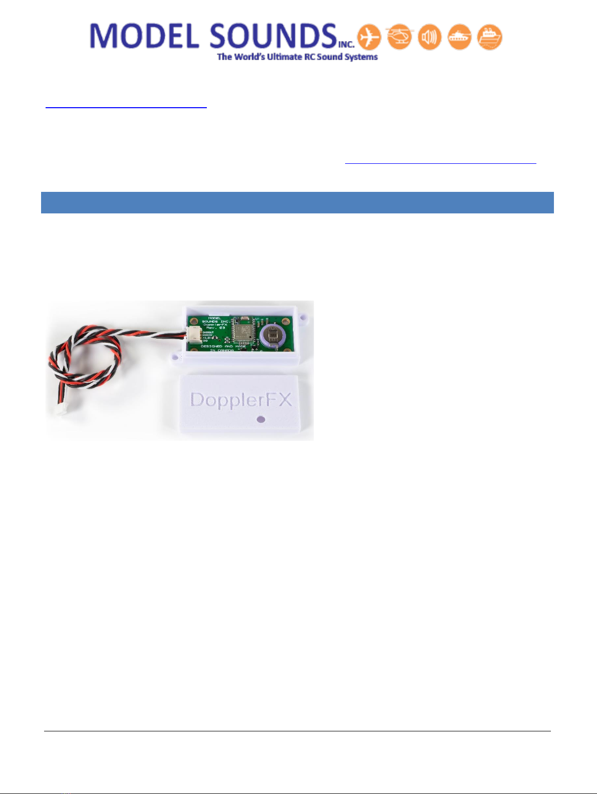
CHAPTER 2 - POWERING THE DOPPLERFX ACCESSORY BOARD
The DopplerFX accessory board requires +3.3Volts power which is drawn from the ShockWave 3
sound module through the provided four-wire accessory cable. This same power provides charging
current for the on-board re-chargeable coin-cell backup battery.
When it is first received, it is advisable to power up the DopplerFX board from the ShockWave 3
board and its receiver battery for a period of 24 hours to charge up its rechargeable coin-cell backup
battery.
CHAPTER 3 –HOW TO OPERATE YOUR DOPPLERFX ACCESSORY BOARD
The ShockWave 3 sound module has SOUND3 RC input pins on its HEADER1 (at the bottom left-hand
side of the board). Refer to the printed quick-start guide that came with the sound module.
Pins 1, 2, 3 on that HEADER1 is configured by default to support an optional input from a spare RC
receiver channel to control the DopplerFX feature. This input can be used to both reset the Observer
Position and to remotely enable and disable the DopplerFX feature.
Pin 1 is system GND, or battery –ve, pin 2 is receiver power, pin 3 carries the DopplerFX RC receiver
signal from the radio receiver into the ShockWave 3 board.
To use this input effectively, it should be used with a three-position switch on your radio with the
centre position being the OFF position. One direction is used to reset the Observer Position and the
other direction is used to remotely enable and disable the DopplerFX feature.
Other than this, operation of the DopplerFX board is completely automatic and it will use settings
contained in the DopplerFXSettings.txt file on the microSD card.
SETTING THE OBSERVER POSITION
The only thing you may want to change during operation is the Observer Position. This position is the
refence location that the ShockWave 3 sound module uses to determine if the model is approaching
towards or receding away from that position. And this position is the point at which maximum change
in Doppler Frequency shift will be heard as the model flies by.
This position is ordinarily set at the location of the model when it acquires a satellite fix and therefore
has a known position. For maximum Doppler Shift effect, the pilot may wish to reset the Observer
Position to a point on the flight line that is close to his/her own position. Or in a scale model
competition, the pilot may wish to reset the Observer Position to near the judge’s station so they can
hear the maximum effect.

DopplerFX®Rev. 03 Quick Start Guide Page 3 of 4 Published: November 12, 2020
© Model SoundsTM Inc.
This resetting of the Observer Position can be done remotely using a 3-position switch on a spare radio
channel whose receiver output is connected to the SOUND3 input of the ShockWave 3 sound module.
CHAPTER 4 - HOW DO I KNOW WHEN I HAVE A SATELLITE FIX?
When first powered up or when powered up a long distance from when it was previously powered, the
“satellites in view” may be different and the time to get the first position fix may be as long as 1
minute or so. This time is called the Time To First Fix (TTFF). Under these circumstances it is called a
“cold start”.
Subsequently, as long as the backup battery is charged, and if you power-up the ShockWave 3 and
DopplerFX board in roughly the same location as last time, this time will be much less –just a few
seconds. This is called a “hot-start”. Please be patient during this time as it is important this time be
allowed for the Observer Position to be obtained.
THE DOPPLERFX LED INDICATOR
The DopplerFX Accessory board has a dual-purpose Green LED. The Green LED will light whenever
power is applied to the board. Once a satellite fix is obtained it will flash on and off once per second as
a satellite fix acquired indicator.
However, since the DopplerFX board is installed inside the model, this LED is of little use to the user, so
there needs to be an external mechanism to indicate when a satellite fix has been obtained.
USING SYSTEM SOUNDS FOR DOPPLERFX EVENT NOTIFICATIONS
The ShockWave 3 module can make system sound announcements to notify you of events such as
Satellite Fix Acquired or Lost, Observer Position Set and some others. These system sound
announcements can be turned on and off by the user using text entries in a DopplerFXSettings.txt file
on the microSD card. They can also be changed in the ShockWave 3 PC software
Control Panel->DopplerFX Tab.
This DopplerFXSettings.txt file is mandatory, and if it is not present, the ShockWave 3 module will
create one with default values when it is powered up.

DopplerFX®Rev. 03 Quick Start Guide Page 4 of 4 Published: November 12, 2020
© Model SoundsTM Inc.
CHAPTER 5 –THE DOPPLERFX BACKUP BATTERY
When a GNSS receiver is first powered up it does a “Cold Start”. This means that it searches for
available satellites and builds a small database of available start-up information and other essential
data. If there is a backup battery present, this start-up information is stored in volatile memory (RAM)
that would otherwise be lost when its main power is removed, as when the electric power system in
the model is switched off.
Since a cold start can take up to a minute or more to perform, by storing the information in backup
memory, it can perform a “Hot Start” next time which usually takes less than 10 seconds. The current
drain when in backup mode is only about 7uA and the 3V coin-cell will last about 2430 hours (about
101 days) without being recharged. It will likely run down during the winter months when the plane is
not in use and will start-up again in Cold Start mode the first time it is powered up in the next flying
season.
It is recommended to charge up the battery at least twice during the winter months. The battery gets
charged automatically when the main +3.3V power from the ShockWave 3 sound module is applied.
Care should be taken to NOT short circuit the small coin backup battery with stray tools or wires.
Other manuals for DopplerFX
1
Table of contents