Pack 13
Stage 51
Mounting the pedals
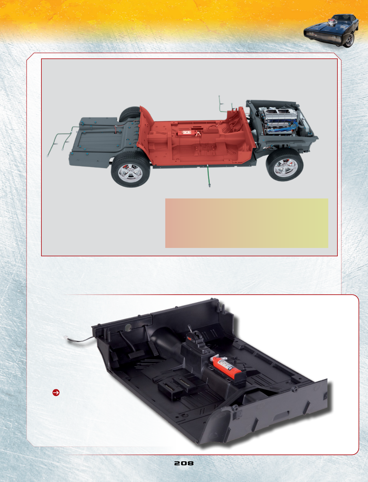
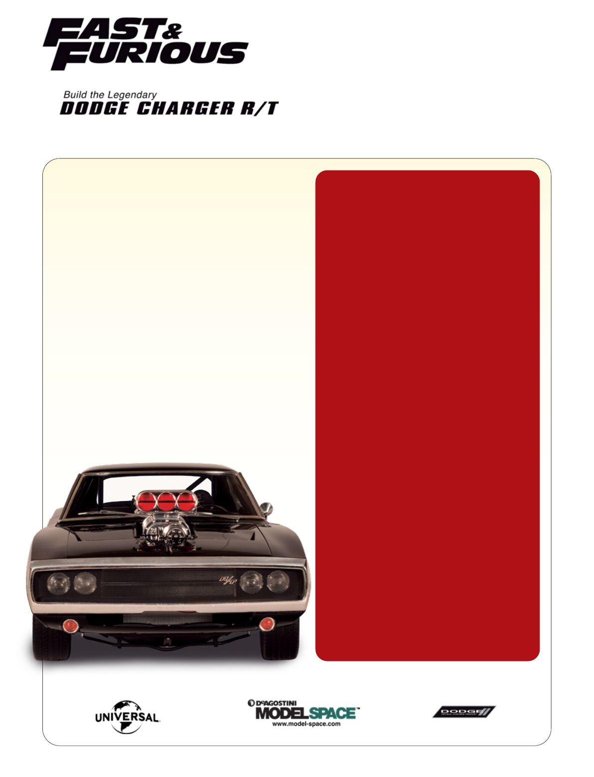
Stage 52
Assembling the floor
Stage 53
Assembling the seat (I)
Stage 54
Assembling the seat (II)
Stage 55
Assembling the dashboard (I)
Editorial by: Milanoedit srl, milanoedit.com
Translation by: TperTradurre
Picture credits: NBCUniversal Archive
© 2019 Universal City Studios LLC.
Fast & Furious and all related marks and characters are trademarks
and copyrights of Universal Studios.
All Rights Reserved.
Dodge, HEMI and related logos, vehicle model names and trade
dress are trademarks of FCA US LLC and used under license by
Premium and Collectibles Trading Co. Ltd. ©2019 FCA US LLC.
© 2019 Editorial Planeta DeAgostini S.A.U.
Todos los derechos reservados.
© 2019 De Agostini Publishing Italia S.p.A.
Tutti i diritti riservati.
Warning: Not suitable for children under the age of 14.
This product is not a toy and is not designed or intended for use
in play.
Items may vary from those shown.