STEP 92-1
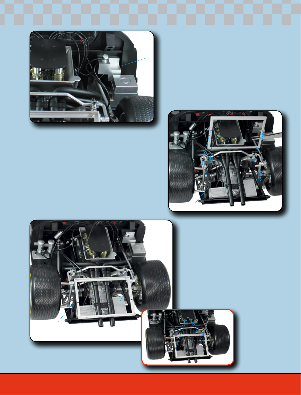
Get the piece you assembled in the
previous stage. Press the air intake
manifold (91B) onto the front left
headlight housing (91A).
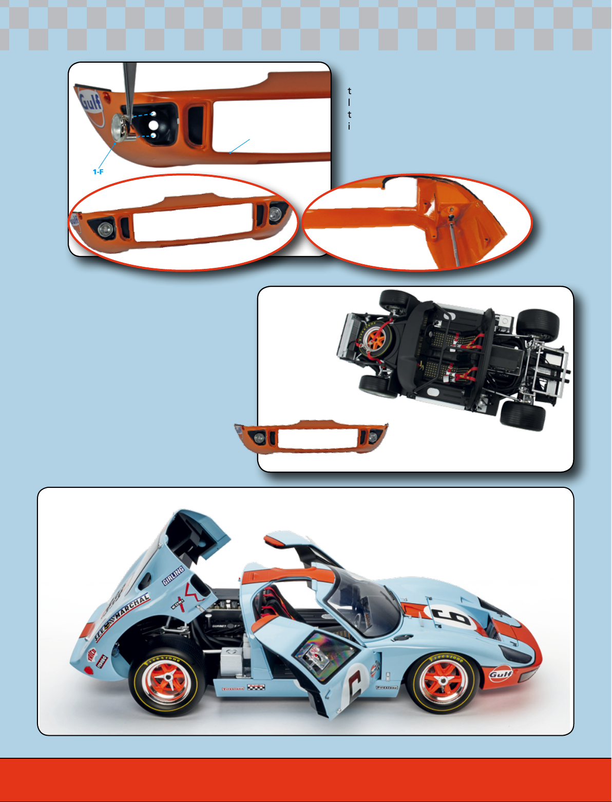
STEP 92-3
Secure the lower front panel (90A)
and front left headlight housing
(91A) assembly with three FD01
screws. To ensure they t together
perfectly, tighten the two screws at
the ends rst and the central screw
last.
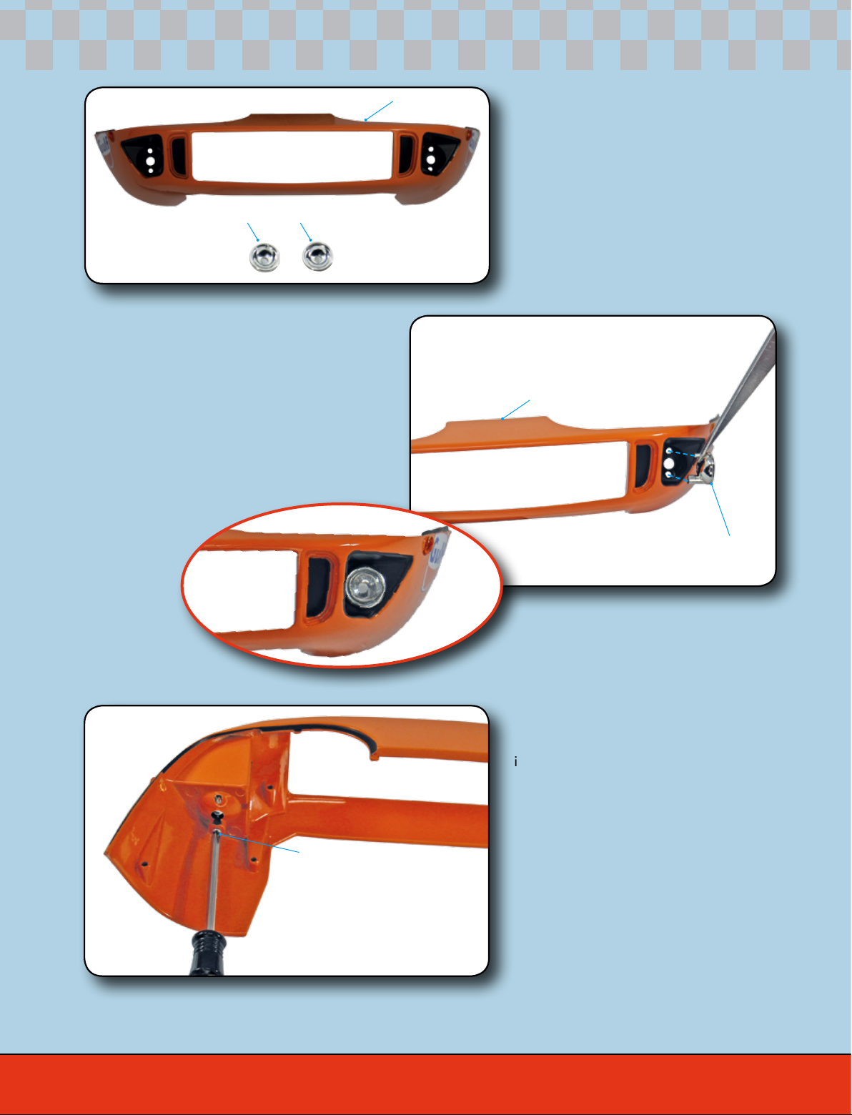
STEP 92-2
Get the lower front panel (90A) and,
from the inside, position the front
left headlight housing (91A), as
shown in the photo. Locate the three
indicated mounting points and attach
the housing to the panel.
91-A
91-A
91-A
91-B
90-A
90-A
FD01
FD01
FD01
ford gt
349