PORSCHE CARRERA 911
4
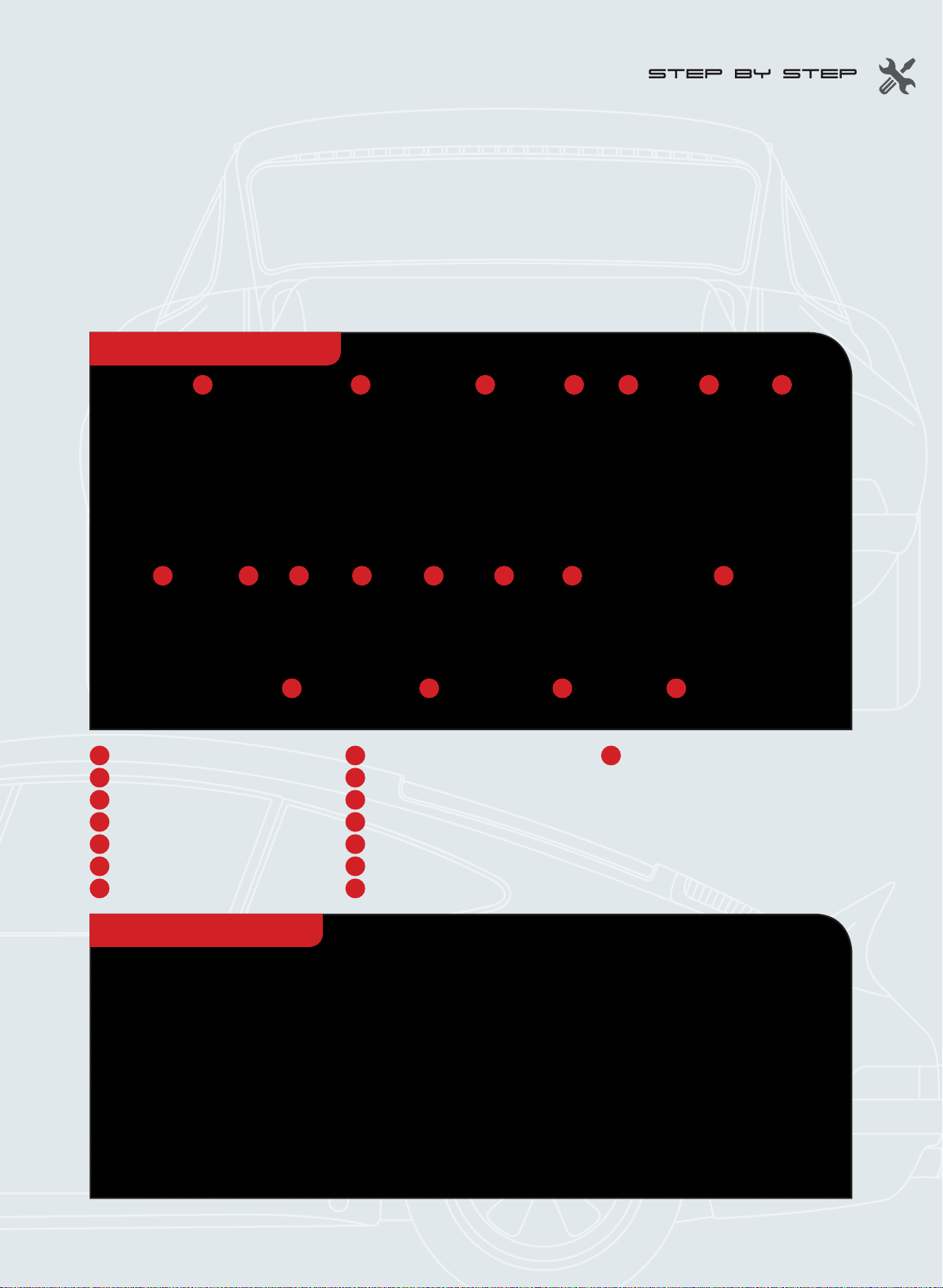
STEP 1 - 4
Secure the boot lock
plate to the inside of the
boot reinforcement with
two AP screws.
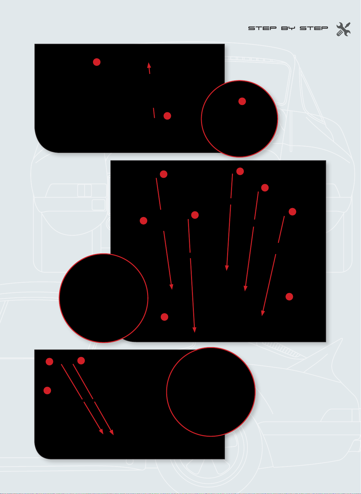
STEP 1-1
Remove the two pads from
the sprue (1E). Insert a
pad into each of the two
indicated holes in the
boot reinforcement (1D).
Push them into the holes
as far as they will go.
STEP 1-2
Insert the boot lock (1I) into
the boot lock plate (1H)and
secure with a BP screw.
STEP 1-3
Pass the pin (1J) through the
washer (1M) and the spring
(1K), then up through the lock
plate. Make sure you have the
washer the right way around.
Remove the C-rings (1L) from
their sprue in the same way
as the two pads. Push the pin
through the plate and place
the C-ring around the pin, as
shown.
1E
1E
1E
1D
1I 1H
BP
1K 1L
1M
1J
AP
AP
1D
1E
1H