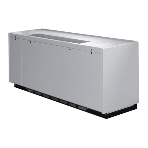
Modine Manufacturing SSD Manual

8-504.11
5H1015480001
INSTALLATION AND SERVICE MANUAL
Ductless Split Ceiling Cassette
Models SSD, SSH and SCW
Models CSD, CSH and CCW
December, 2023
THIS MANUAL IS THE PROPERTY OF THE OWNER.
PLEASE BE SURE TO LEAVE IT WITH THE OWNER WHEN YOU LEAVE THE JOB.
WARNING
1. Improper installation, adjustment, alteration,
service or maintenance can cause property
damage, injury or death, and could cause
exposure to substances which have been
determined by various state agencies to cause
cancer, birth defects or other reproductive
harm. Read the installation, operating and
maintenance instructions thoroughly before
installing or servicing this equipment.
2. Units with DX evaporator coils (refer to
model nomenclature) contain R-410A high
pressure refrigerant. Hazards exist that could
result in personal injury or death. Installation,
maintenance, and service must only be
performed by an HVAC technician qualied
in R-410A refrigerant and using proper tools
and equipment. Due to much higher pressure
of R-410A refrigerant, DO NOT USE service
equipment or tools designed for refrigerants
other than R410A.
AVERTISSEMENT
1. Une installation, un réglage, une altération, une
réparation ou une maintenance impropre risque
de causer des dommages, des blessures ou
la mort, et d’engendrer une exposition à des
substances dont certains États ont déterminé
qu’elles étaient cancérogènes ou pouvaient
causer des malformations à la naissance et
des problèmes de reproduction. Lisez bien
les instructions d’installation, d’utilisation et de
maintenance avant d’installer ou de réparer cet
appareil.
AVERTISSEMENT
2. Les unités munies de serpentins évaporateurs
DX (reportez-vous à la nomenclature du
modèle) contiennent du uide frigorigène à
haute pression R-410A. Des dangers existent
qui, s’ils se matérialisent, pourraient entraîner
des blessures ou la mort. L’installation,
l’entretien et le service ne doivent être eectués
que par un technicien de CVC qualié quant à
l’usage du uide frigorigène R-410A en utilisant
les outils et l’équipement appropriés. En raison
de la pression beaucoup plus élevée du uide
frigorigène R-410A, N’utilisez PAS des outils
ou de l’équipement de service qui ne sont pas
conçus spéciquement pour le R-410A.
IMPORTANT
1. The use of this manual is specically intended
for a qualied installation and service agency. A
qualied installation and service agency must
perform all installation and service of these
appliances.
2. Units with DX evaporator coils (refer to model
nomenclature) contain the refrigerant R-410A.
Review the R-410A Material Safety Data Sheet
(MSDS) for hazards and rst aid measures.
IMPORTANT
1. Ce manuel est spéciquement destiné
au personnel d’une entreprise qualiée
d’installation et d’entretien. Toutes les
opérations d’installation et d’entretien doivent
être conées à une entreprise qualiée.
2. Les unités munies de serpentins évaporateurs
DX (reportez-vous à la nomenclature du
modèle) contiennent du uide frigorigène
R-410A. Pour les dangers et les mesures de
premiers soins, consultez la che signalétique
du R-410A.

28-504.11
IMPORTANT
1. Refrigerant charging should only be carried out
by an EPA-certied air conditioning contractor.
2. This appliance is not intended to be operated
or serviced by persons (including children) with
reduced physical, sensory or mental capabilities,
or lack of experience and knowledge, unless
they have been given supervision or instruction
concerning use of the appliance by a person
responsible for their safety.
3. Children should be supervised to ensure that
they do not play with the appliance.
IMPORTANT
1. L’ajout de frigorigène doit être coné à un
spécialiste de la climatisation certié par
l’agence de la protection de l’environnement
(EPA) du gouvernement américain.
2. Cet appareil n’est pas conçu pour être utilisé
ou entretenu par des personnes (y compris
des enfants) dont les capacités physiques,
sensorielles ou mentales sont réduites, ou qui
n’ont pas l’expérience et les connaissances
susantes, à moins d’être supervisées ou
d’avoir obtenu des directives concernant
l’utilisation de l’appareil par une personne
responsable de leur sécurité.
3. Les enfants doivent être supervisés pour
s’assurer qu’ils ne jouent pas avec l’appareil.
INSPECTION ON ARRIVAL
1. Inspect unit upon arrival. In case of damage, report
immediately to transportation company and your local factory
sales representative.
2. Check serial plate on unit to verify that the power supply
meets available electric power at the point of installation.
3. Inspect unit upon arrival for conformance with description of
product ordered (including specications where applicable)
TABLE OF CONTENTS
Special Precautions .............................................................3
Hazard Intensity Levels ........................................................3
Special Design Requests .....................................................5
Unit Location ........................................................................6
Unpacking ..........................................................................6
Blank O Pieces ................................................................6
Preparation ........................................................................6
Ceiling Opening Sizes ........................................................6
Positioning Wall Mounted Thermostat ...............................7
Installation ............................................................................8
Hanger Bolts ......................................................................8
Installation Guide ...............................................................8
Condensate Piping .............................................................9
Duct Collars .......................................................................9
Piping Installation .............................................................10
Wiring ...............................................................................11
Disconnect Switch ............................................................12
Terminal Strip Connections ..............................................12
Remote Condensing Unit Terminal Strip Connections .....12
Fascia Assembly ..............................................................12
Start-Up Procedure ............................................................13
Start Up Sheet - Example ..................................................14
Sequence of Operation ......................................................16
Micro-Processor Operation ................................................18
Dimensions ........................................................................20
Small Chassis: Chilled Water Units .................................20
Medium Chassis: Chilled Water Units ..............................21
Large Chassis: Chilled Water Units .................................22
Medium Chassis: DX and Heat Pump units .....................23
Large Chassis: DX and Heat Pump units ........................24
DX Cooling Only and Heat Pump Units - IP Units ...........26
DX Cooling Only and Heat Pump Units - SI Units ...........27
Chilled Water Units - IP Units ...........................................28
Chilled Water Units - SI Units ..........................................29
Exploded Unit Drawing & Parts List – Chilled Water .........30
Exploded Unit Drawing & Parts List – DX & Heat Pump ....31
Maintenance ......................................................................32
Disassembly Procedure ...................................................33
Replacement Parts ..........................................................33
Model Identication ............................................................34
Troubleshooting .................................................................35

3
8-504.11
SPECIAL PRECAUTIONS
SPECIAL PRECAUTIONS
THE INSTALLATION AND MAINTENANCE INSTRUCTIONS
IN THIS MANUAL MUST BE FOLLOWED TO PROVIDE
SAFE, EFFICIENT, AND TROUBLE-FREE OPERATION. IN
ADDITION, PARTICULAR CARE MUST BE EXERCISED
REGARDING THE SPECIAL PRECAUTIONS LISTED BELOW.
FAILURE TO PROPERLY ADDRESS THESE CRITICAL
AREAS COULD RESULT IN PROPERTY DAMAGE OR LOSS,
PERSONAL INJURY, OR DEATH. THESE INSTRUCTIONS
ARE SUBJECT TO ANY MORE RESTRICTIVE LOCAL OR
NATIONAL CODES.
PRÉCAUTIONS PARTICULIÈRES
LES INSTRUCTIONS D'INSTALLATION ET D'ENTRETIEN DE
CE MANUEL DOIVENT ÊTRE OBSERVÉES POUR ASSURER
UN FONCTIONNEMENT SÉCURITAIRE, EFFICACE ET
FIABLE. DE PLUS, LES PRÉCAUTIONS PARTICULIÈRES CI-
APRÈS DOIVENT ÊTRE RIGOUREUSEMENT RESPECTÉES.
SINON, IL Y AURAIT RISQUE DE DÉGÂTS MATÉRIELS
OU DE PERTE, DE BLESSURE PERSONNELLE OU DE
MORT D'HOMME. CES INSTRUCTIONS SONT SUJETTES
À TOUTE DISPOSITION PLUS RESTRICTIVE DES CODES
PROVINCIAL OU NATIONAL.
HAZARD INTENSITY LEVELS
1. DANGER: Indicates an imminently hazardous situation
which, if not avoided, WILL result in death or serious injury.
2. WARNING: Indicates a potentially hazardous situation
which, if not avoided, COULD result in death or serious
injury.
3. CAUTION: Indicates a potentially hazardous situation
which, if not avoided, MAY result in minor or moderate
injury.
4. IMPORTANT: Indicates a situation which, if not avoided,
MAY result in a potential safety concern.
HIÉRARCHIE DES NIVEAUX DE RISQUES
1. DANGER: Indique un danger imminent qui, s'il n'est pas
évité, entraînera INÉVITABLEMENT des blessures graves,
voire mortelles.
2. AVERTISSEMENT: Indique un danger potentiel qui, s'il
n'est pas évité, RISQUE d'entraîner des blessures graves,
voire mortelles.
3. ATTENTION: Indique un danger potentiel qui, s'il n'est
pas évité, PEUT entraîner des blessures mineures ou
modérées.
4. IMPORTANT: Indique une situation qui, si elle se
matérialise, PEUT entraîner des risques pour la sécurité
des personnes.
DANGER
Appliances must not be installed where they may be exposed
to potentially explosive or ammable atmosphere.
DANGER
Les appareils ne doivent pas être installés à un endroit où ils
risquent d’être exposés à une atmosphère potentiellement
explosive ou inammable.
WARNING
1. Disconnect power supply before making wiring connections
or working on this equipment. Follow all applicable safety
procedures to prevent accidental power up. Failure to do
so can result in injury or death from electrical shock or
moving parts and may cause equipment damage.
2. All appliances must be wired strictly in accordance with
the wiring diagram furnished with the appliance. Any wiring
dierent from the wiring diagram could result in a hazard to
persons and property.
3. Any original factory wiring that requires replacement must
be replaced with wiring material having a temperature
rating of at least 221°F (105°C).
4. Ensure that the supply voltage to the appliance, as
indicated on the serial plate, is not 5% greater than rated
voltage.
5. When servicing or repairing this equipment, use only
factory-approved service replacement parts. Refer to
the rating plate on the appliance for complete appliance
model number, serial number, and company address. Any
substitution of parts or controls not approved by the factory
will be at the owner’s risk.
AVERTISSEMENT
1. Débranchez l’alimentation électrique avant d’eectuer
des connexions ou de travailler sur l’appareil. Respectez
toutes les procédures de sécurité qui s’appliquent pour
éviter toute mise en marche accidentelle. Le non-respect
de cette directive peut entraîner des blessures ou la mort
causées par un choc électrique ou des pièces mobiles, en
plus d’endommager l’appareil.
2. Tous les appareils doivent être branchés de manière
strictement conforme au diagramme fourni. Tout câblage
diérent de celui du schéma peut créer des risques de
dommages matériels ou de blessures.
3. Tout câblage usine d’origine exigeant un remplacement
doit être remplacé par un câble d’indice thermique nominal
de 221 °F (105 °C).
4. Assurez-vous que la tension d’alimentation de l’appareil,
comme indiqué sur la plaque de série, n’est pas de 5 %
supérieure à la tension nominale.
5. Pour l’entretien et les réparations de cet appareil, utilisez
uniquement des pièces d’origine certiées. Pour la liste
complete des pièces de rechange, consultez Modine
Manufacturing Company. Le numéro de modèle complet,
le numéro de série et l’adresse du fabricant gurent sur la
plaque signalétique xée à l’appareil. Toute substitution de
pièce ou decommande non approuvée par le fabricant sera
aux risques du propriétaire.
48-504.11
SPECIAL PRECAUTIONS
CAUTION
1. Do not overcharge the refrigeration system. This can lead
to elevated compressor discharge pressure and possibly
ooding to the compressor with liquid.
2. Units not approved for use in potable water systems.
3. Hot water supplied to the hot water heating option must not
exceed 200ºF (93°C) temperature or 125 PSIG (862 kPa)
pressure.
4. Ensure that the supply voltage to the appliance, as
indicated on the serial plate, is not 5% less than the rated
voltage.
5. In order to avoid a hazard due to inadvertent resetting of
the thermal cut-out, this appliance must not be supplied
through an external switching device, such as a timer, or
connected to a circuit that is regularly switched on and o
by the utility.
6. Do not attempt to reuse any mechanical or electrical
component which has been wet. Such component must be
replaced.
7. When servicing the unit, some components may be hot
enough to cause pain or injury. Allow time for cooling of hot
components before servicing.
ATTENTION
1. Ne surchargez pas le système de réfrigération. Cela
peut entraîner une pression d’évacuation élevée du
compresseur et possiblement son inondation.
2. Ces unités ne sont pas approuvées pour l’usage dans des
systèmes à eau potable.
3. La température de l’eau chaude alimentée en vertu de
l’option de chauage de l’eau chaude ne doit pas dépasser
200 °F (93 °C) ou une pression de 125 lb/po² (862 kPa).
4. Vériez que la tension d’alimentation de l’appareil n’est pas
inférieure de plus de 5 % à la tension nominale inscrite sur
la plaque de série.
5. An d’éviter tout danger causé par la réinitialisation
involontaire du coupe-circuit thermique, cet appareil ne
doit pas être alimenté par l’entremise d’un dispositif de
commutation externe, comme une minuterie, ou relié à un
circuit qui est régulièrement mis en marche et coupé par le
service public.
6. Ne tentez pas de réutiliser un composant mécanique ou
électrique qui a été mouillé. Ces composants doivent être
remplacés.
7. Durant l’entretien de l’unité, certains composants peuvent
être assez chauds pour causer de la douleur ou une
blessure. Laissez les composants chauds se refroidir avant
de procéder à tout entretien.
IMPORTANT
1. Unit Performance will be signicantly reduced at or above
7215 ft (2200 m) and should not be operated above this
altitude.
2. For ceiling mounted units, check that the ceiling is capable
of supporting the weight of the unit. If used within a ceiling
grid, the ceiling grid is to be supported separately from the
unit.
3. Units with DX evaporator coils (refer to model
nomenclature) contain the refrigerant R-410A. Review the
R-410A Material Safety Data Sheet (MSDS) for hazards
and rst aid measures.
4. Refrigerant charging should only be carried out by an EPA-
certied air conditioning contractor.
5. Units with DX coils (refer to the model nomenclature) are
partial units, complying with partial unit requirements of UL
60335-2-40, and must only be connected to other units that
have been conrmed as complying to corresponding partial
unit requirements of UL 60335-2-40/CSA C22.2 No. 60335-
2-40, or UL 1995/CSA C22.2 No. 236.
6. No water-ow can cause a freeze condition resulting in
damage to the coil.
7. Never leave the unit lled with water in a building without
heat unless antifreeze has been added.
8. Start up and adjustment procedures, installation, and
service of these appliances must be performed by a
qualied installation and service agency.
9. All refrigeration checks must be made by a qualied
R-410A refrigeration technician.
10. Do not release refrigerant to the atmosphere. When adding
or removing refrigerant, all national, state/province and
local laws must be followed
11. To check most of the Possible Remedies in the
Troubleshooting guide listed in Table 36.1, refer to the
applicable sections of the manual.

5
8-504.11
SPECIAL PRECAUTIONS
IMPORTANT
1. La performance de l’unité sera grandement réduite à une
altitude de 7215 pieds (2200 m) et elle ne doit pas être
utilisée au-delà de cette hauteur.
2. Pour les unités installées au plafond, vériez que le plafond
peut soutenir le poids de l’unité. En cas d’utilisation au
sein d’un support de plafond, ce dernier doit être soutenu
séparément de l’unité.
3. Les unités munies de serpentins évaporateurs DX
(reportez-vous à la nomenclature du modèle) contiennent
du uide frigorigène R-410A. Pour les dangers et les
mesures de premiers soins, consultez la che signalétique
du R-410A.
4. L’ajout de frigorigène doit être coné à un spécialiste de
la climatisation certié par l’agence de la protection de
l’environnement (EPA) du gouvernement américain.
5. Les unités munies de serpentins DX (reportez-vous à la
nomenclature du modèle) sont des unités partielles, se
conformant aux exigences relatives aux unités partielles
UL 60335-2-40, et ne doivent être reliées qu’à d’autres
unités qui sont conrmées comme étant conformes aux
exigences correspondantes des unités partielles UL 60335-
2-40/CSA C22.2 Nº 60335-2-40 ou UL 1995/CSA C22.2 Nº
236.
6. L’absence d’écoulement d’eau risque de causer une
condition de gel et d’endommager le serpentin.
7. Ne laissez jamais l’appareil rempli d’eau dans un immeuble
non chaué sans lui ajouter de l’antigel.
8. Les procédures de démarrage et de réglage, l’installation
et le service de ces appareils doivent être conés à un
centre d’installation et de service qualié.
9. Toutes les vérications de réfrigération doivent être
eectuées par un technicien de la réfrigération qualié en
matière de uide frigorigène R-410A.
10. Ne rejetez pas de uide frigorigène dans l’atmosphère.
Respectez toutes les lois locales, provinciales/étatiques et
nationales lors de l’ajout ou du retrait de uide frigorigène.
11. Pour essayer la plupart des solutions possibles suggérées
dans le guide de dépannage du Table 36.1, reportez-vous
aux sections correspondantes du manuel.
Table 5.1 - SI (Metric) Conversion Factors
To Convert Multiply
By
To
Obtain
To
Convert
Multiply
By
To
Obtain
"W.C. 0.24 kPa CFH 1.699 m3/min
psig 6.893 kPa Btu/ft30.0374 mJ/m3
°F (°F-32) x
0.555 °C pound 0.453 kg
inches 25.4 mm Btu/hr 0.000293 kW
feet 0.305 meters gallons 3.785 liters
CFM 0.028 m3/min psig 27.7 "W.C.
SPECIAL DESIGN REQUESTS
Units are sometimes built units with special features as
requested by the customer. This manual only covers standard
features and does not include any changes made for special
feature requests by the customer. Units built with special
features are noted with a 5-digit SPO (Special Product Order)
Number on the Serial Plate.

68-504.11
UNIT LOCATION
UNIT LOCATION
DANGER
Appliances must not be installed where they may be exposed
to potentially explosive or ammable atmosphere.
DANGER
Les appareils ne doivent pas être installés à un endroit où ils
risquent d’être exposés à une atmosphère potentiellement
explosive ou inammable.
IMPORTANT
Unit Performance will be signicantly reduced at or above
7215 ft (2200 m) and should not be operated above this
altitude.
IMPORTANT
La performance de l’unité sera grandement réduite à une
altitude de 7215 pieds (2200 m) et elle ne doit pas être
utilisée au-delà de cette hauteur.
Unpacking
Remove the banding straps and lift the cardboard lid. Remove
the fascia, packed in bubble wrap, and polystyrene packing
pieces to expose the unit.
When removing the unit chassis from the box, the four corner
brackets should be utilized for lifting. In order to protect the
fascia from dirt and damage, it should be returned to the box
until it is ready to be installed.
Blank Off Pieces
When supply air branch ducting is to be used, polystyrene
pieces for blanking o fascia openings are included with the
fascia packing. Up to two opposing sides may be blanked o.
See Installation – Duct Collars on page 9.
Preparation
Before any installation work commences, the condensing unit
location (where applicable), pipe work sizes and routes should
be designed in accordance with good refrigeration practice.
When locating the unit, consider the following:
1. Ensure the ceiling structure that is adequate for
the required mounting provisions as outlined in the
“INSTALLATION” section. Check the ceiling is capable of
supporting the total weight of the unit, piping, refrigerant
and condensate.
2. Before installation, ensure that the correct electrical power
supplies are available for the unit.
3. Piping, electrical panel and condensate pump access panel
should be readily accessible for maintenance purposes.
A clearance of 2 ft (0.61 m) is recommended around the
electrical panel and condensate pump access panel.
4. The unit should not be positioned less than 5 ft (1.5 m)
from a wall or similar obstruction, or in a position where the
discharge air could blow directly on to the thermostat.
5. The unit should not be positioned directly above any
obstructions.
6. For units with supplementary electric heat (Digit 9 = A), the
minimum clearance from the unit to combustible surfaces is
0 in (0cm).
7. The unit must be installed square and level.
8. The condensate drain should have downward slope (1
in per 100 in (2.54 cm per 254 cm)) in a horizontal run
between unit and drain. Maximum condensate pump lift is
30 in (76.2 cm).
9. There should be sucient room above the false ceiling
for installing the unit. Minimum distance as shown in
Figure 6.1 and Table 6.1.
10. In case of high humidity, clogged or damaged condensate
piping, incorrect installation or faulty condensate pump,
water may drip from the unit. Do not install the appliance
where dripping water can cause damage.
Figure 6.1 - Minimum Distance to Ceiling
A
Table 6.1 - Minimum Distance to Ceiling
Unit Conguration
(Digits 2,3)
Nominal Capacity
(Digits 4,5) A
CW
08 & 12 12.75 in 32.40 cm
18 & 20 11.50 in 29.20 cm
33 & 36 13.50 in 34.30 cm
SD/SH 18, 24, 30, 36, 42
Ceiling Opening Sizes
An opening in the false ceiling will then have to be cut to the
size shown in Table 6.2.
Table 6.2 - Ceiling Opening Sizes
Unit Conguration
(Digits 2,3)
Nominal Capacity
(Digits 4,5) L x W
CW
08 & 12 23.00 in x
23.00 in
58.42 cm x
58.42 cm
18 & 20 34.00 in x
34.00 in
86.36 cm x
86.36 cm
33 & 36 46.00 in x
34.00 in
116.8 cm x
86.36 cm
SD/SH
18 & 24 34.00 in x
34.00 in
86.36 cm x
86.36 cm
30, 36, & 42 46.00 in x
34.00 in
116.8 cm x
86.36 cm

7
8-504.11
UNIT LOCATION
Positioning Wall Mounted Thermostat
For proper temperature control, the thermostat should be
mounted as follows:
1. Position the thermostat approximately 48 in (122 cm) above
oor level.
2. Do not position thermostat where it can be directly aected
by the unit’s discharge air stream.
3. Avoid external walls and drafts from windows and doors.
4. Avoid positioning near shelves and curtains as these
restrict air movement.
5. Avoid heat sources e.g. direct sunlight, heaters, dimmer
switches and other electrical devices.

88-504.11
INSTALLATION
Installation
IMPORTANT
For ceiling mounted units, check that the ceiling is capable of
supporting the weight of the unit. If used within a ceiling grid,
the ceiling grid is to be supported separately from the unit.
IMPORTANT
Pour les unités installées au plafond, vériez que le plafond
peut soutenir le poids de l’unité. En cas d’utilisation au
sein d’un support de plafond, ce dernier doit être soutenu
séparément de l’unité.
Hanger Bolts
The hanger bolts can now be installed (use 3/8” all thread rod)
at the centers shown in Figure 8.1 and Figure 8.2.
Figure 8.1 - Hanger Bolt Mounting Dimensions
A
A
B
Table 8.1 - Hanger Bolt Mounting Dimensions
Unit
Conguration
(Digits 2,3)
Nominal
Capacity
(Digits 4,5) A B
CW
08, 12 19.5 in 49.5 cm 23.0 in 58.4 cm
18, 20 28.5 in 72.4 cm 31.5 in 80.0 cm
33, 36 28.5 in 72.4 cm 43.5 in 110.5 cm
SD/SH 18, 24 28.5 in 72.4 cm 31.5 in 80.0 cm
30, 36, 42 28.5 in 72.4 cm 43.5 in 110.5 cm
Refer to the manufacturer’s hanger bolts technical sheet to check the strength of
the unit mounting hanger bolts. Ensure the bolts can hold the weight of the unit.
Refer to Table 26.1, Table 27.1,Table 28.1 andTable 29.1 for unit weights.
Installation Guide
An installation guide is included in the Owner Information packet
provided with the unit. The installation guide sets the proper
height between the chassis and ceiling. Prepare the installation
guide by folding the at metal piece, by hand, along the
perforations as shown in Figure 8.2.
Figure 8.2 - Installation Guide Setup
FOLD TAB UP
FOLD SIDE BACK
Use an adequate number of personnel when moving the unit.
A lifting device or at least two personnel should be used to
lift the unit. The unit can be lifted onto the hanging rods and
leveled at the correct distance from the ceiling with the aid of the
installation guide.
1. Hold the tab on the installation guide against the bottom
of the cassette case with the guide pointing away from the
cassette. See Figure 8.3.
2. Adjust the height of the cassette until the guide is level with
the bottom of the false ceiling.
Figure 8.3 - Installation Guide Position
OUTER CASE
INSULATION
FALSE CEILING
GUIDE IN POSITION
CASSETTE CASE
INNER CASE
INSULATION
TAB
3. Secure the unit in position with locknuts and washers
on both sides of the unit bracket. It is recommended to
have two 3/8” locknuts and washers on the bottom of the
threaded rod. Ensure the threaded rod does not protrude
more than 2 in (5 cm) below the mounting bracket as
shown in Figure 9.1.

9
8-504.11
INSTALLATION
Figure 9.1 - Threaded Rod Dimension
Threaded Rod
< 2 in (5 cm)
3/8 in
Condensate Piping
The unit is supplied with a 3/8" ID exible hose for connection to
copper or plastic drain piping.
When installing the unit consider the following:
1. Maximum pump lift is 30 in (76.2 cm).
2. The highest point in the condensate piping should be as
close to the unit as possible.
3. Condensate piping should slope downwards in the direction
of water ow with a minimum gradient of 1 in per 100 in
(2.54 cm per 254 cm). There must not be any upward
gradients other than in the rst 30 in (76.2 cm) of piping
from the unit. Once the piping begins the downward
gradient, the piping must continue to be in a downward
gradient. See Figure 9.2.
Figure 9.2 - Condensate Piping
30 in
(76.2 cm)
Max
4. When multiple units are connected to a common
condensate drain, ensure the drain is large enough to
contain the volume of condensate from all units. It is
recommended to have an air vent in the condensate piping
to prevent any air locks.
5. Condensate piping must not be installed where it may be
exposed to freezing temperatures.
Duct Collars
Supply air branch duct and outside air duct collars can be
attached to the unit chassis by following the below steps:
Supply Air Duct Collars:
1. Up to two supply air ducts can be attached per unit.
2. Place the polystyrene blanking strip in the fascia supply air
opening on the same side where the supply duct collar is to
be installed.
Outside Air Duct Collars:
1. Two outside air openings are available on small casing
sizes (size 08 & 12). Three outside air openings are
available on medium and large casing sizes (size 18 and
higher).
2. Replace the washable lter with the pleated lter provided
with the fresh air duct collar kit.
3. To maximize the amount of outside air through the
knockouts, use all available fresh air openings, the pleated
lter, and high fan speed.
Installing Outside and/or Supply Air Duct Collars:
1. Refer to the dimensional drawing on page 20 page 24
to for knock-out hole locations.
2. The insulation is pre-cut to aid location and removal of the
relevant section. Rub hand across surface of insulation to
reveal exact location of knock-out.
3. Remove the metal knockout from the chassis.
4. Place the duct collar’s tabs inside the duct collar ange’s
opening. Bend the tabs around the duct collar ange’s
opening.
5. Using eld provided self-tapping screws, attach the duct
ange and collar to the chassis with the bent tabs being
sealed in between the unit chassis and duct collar ange.
See Figure 9.3 for duct collar assembly.
Figure 9.3 - Duct Collar Assembly
DUCT COLLAR
DUCT COLLAR FLANGE
UNIT CHASSIS
OUTSIDE AIR KNOCKOUT
Note:See Figure 20.1, Figure 21.1, Figure 22.1, Figure 23.1
and Figure 24.1 for Branch Duct and Fresh Air Duct
locations and dimensions.

10 8-504.11
INSTALLATION
Piping Installation
Piping Installation – DX and Heat Pump Units
CAUTION
Do not overcharge the refrigeration system. This can lead
to elevated compressor discharge pressure and possibly
ooding to the compressor with liquid.
ATTENTION
Ne surchargez pas le système de réfrigération. Cela peut
entraîner une pression d’évacuation élevée du compresseur
et possiblement son inondation.
IMPORTANT
1. Units with DX evaporator coils (refer to model
nomenclature) contain the refrigerant R-410A. Review the
R-410A Material Safety Data Sheet (MSDS) for hazards
and rst aid measures.
2. Refrigerant charging should only be carried out by an EPA-
certied air conditioning contractor.
3. Units with DX coils (refer to the model nomenclature) are
partial units, complying with partial unit requirements of UL
60335-2-40, and must only be connected to other units that
have been conrmed as complying to corresponding partial
unit requirements of UL 60335-2-40/CSA C22.2 No. 60335-
2-40, or UL 1995/CSA C22.2 No. 236.
IMPORTANT
1. Les unités munies de serpentins évaporateurs DX
(reportez-vous à la nomenclature du modèle) contiennent
du uide frigorigène R-410A. Pour les dangers et les
mesures de premiers soins, consultez la che signalétique
du R-410A.
2. L’ajout de frigorigène doit être coné à un spécialiste de
la climatisation certié par l’agence de la protection de
l’environnement (EPA) du gouvernement américain.
3. Les unités munies de serpentins DX (reportez-vous à la
nomenclature du modèle) sont des unités partielles, se
conformant aux exigences relatives aux unités partielles
UL 60335-2-40, et ne doivent être reliées qu’à d’autres
unités qui sont conrmées comme étant conformes aux
exigences correspondantes des unités partielles UL
60335-2-40/CSA C22.2 Nº 60335-2-40 ou UL 1995/CSA
C22.2 Nº 236.
Note:Note: R-410A refrigerant is the only approved refrigerant
for this system.
1. The unit should be piped up in accordance with good
refrigeration and/or plumbing practices.
2. The outdoor condensing unit must be connected to the
indoor unit coil using eld supplied refrigerant grade (ACR)
copper tubing that is internally clean and dry. Units should
be installed only with the tubing sizes for the approved
system combination as specied in Table 26.1, and
Table 27.1.
3. See the installation and maintenance manual provided with
the condensing unit for installation, evacuation and system
charge information.
Piping Installation – Hot/Chilled Water Coils
CAUTION
1. Units not approved for use in potable water systems.
2. Hot water supplied to the hot water heating option must not
exceed 200ºF (93°C) temperature or 125 PSIG (862 kPa)
pressure.
ATTENTION
1. Ces unités ne sont pas approuvées pour l’usage dans des
systèmes à eau potable.
2. Ne laissez jamais l’appareil rempli d’eau dans un immeuble
non chaué sans lui ajouter de l’antigel.
IMPORTANT
1. No water-ow can cause a freeze condition resulting in
damage to the coil.
2. Never leave the unit lled with water in a building without
heat unless antifreeze has been added.
IMPORTANT
1. L’absence d’écoulement d’eau risque de causer une
condition de gel et d’endommager le serpentin.
2. Ne laissez jamais l’appareil rempli d’eau dans un immeuble
non chaué sans lui ajouter de l’antigel.
1. Branch piping to and from the unit should include swing
joints to allow for expansion and contraction of the piping
without placing a strain on the unit coil.
2. Install pipe unions and shut-o valves in lines to and from
each coil to allow maintenance or replacement of unit
without shutting down and draining entire system. See
Figure 11.1.
3. Include a circuit setter in return line for water ow
regulation.
4. If the unit is located in an area subject to freezing, it is
recommended a drain valve (hose bib) is eld provided and
installed for each coil line to allow removal of water from
the coil.
5. A pipe line strainer is recommended before each coil.
6. Provide adequate pipe hangers, supports, or anchors to
secure the piping system independently of the unit.
7. On 2-pipe systems with microprocessor controls (Model
Digit 8=M), install the factory provided changeover sensor
on the main supply water line upstream from the unit where
water maintains ow to ensure accurate readings of water
temperature. Wire extension and a plug are included.

11
8-504.11
INSTALLATION
Figure 11.1 -
Hot/Chilled Water Coil Piping Installation
SUPPLY
RETURN
AIR VENT
HOSE BIB DRAIN
STRAINERUNION
UNIONUNION
CIRCUIT
SETTER
SHUT-OFF
VALVE
SHUT-OFF
VALVE
2-WAY
CONTROL VALVE
HOT/CHILLED
WATER COIL
Piping Insulation
Refrigerant, chilled water and condensate pipes should be
insulated right up to the unit chassis to prevent condensation
which can damage the ceiling and objects located below the
piping. Chilled water valves must also be insulated to prevent
sweating.
Wiring
WARNING
1. Disconnect power supply before making wiring connections
or working on this equipment. Follow all applicable safety
procedures to prevent accidental power up. Failure to do
so can result in injury or death from electrical shock or
moving parts and may cause equipment damage.
2. All appliances must be wired strictly in accordance with
the wiring diagram furnished with the appliance. Any wiring
dierent from the wiring diagram could result in a hazard to
persons and property.
3. Any original factory wiring that requires replacement must
be replaced with wiring material having a temperature
rating of at least 221°F (105°C).
4. Ensure that the supply voltage to the appliance, as
indicated on the serial plate, is not 5% greater than rated
voltage.
AVERTISSEMENT
1. Débranchez l’alimentation électrique avant d’eectuer
des connexions ou de travailler sur l’appareil. Respectez
toutes les procédures de sécurité qui s’appliquent pour
éviter toute mise en marche accidentelle. Le non-respect
de cette directive peut entraîner des blessures ou la mort
causées par un choc électrique ou des pièces mobiles, en
plus d’endommager l’appareil.
2. Tous les appareils doivent être branchés de manière
strictement conforme au diagramme fourni. Tout câblage
diérent de celui du schéma peut créer des risques de
dommages matériels ou de blessures.
3. Tout câblage usine d’origine exigeant un remplacement
doit être remplacé par un câble d’indice thermique nominal
de 221 °F (105 °C).
4. Assurez-vous que la tension d’alimentation de l’appareil,
comme indiqué sur la plaque de série, n’est pas de 5 %
supérieure à la tension nominale.
CAUTION
1. Ensure that the supply voltage to the appliance, as
indicated on the serial plate, is not 5% less than the rated
voltage.
2. In order to avoid a hazard due to inadvertent resetting of
the thermal cut-out, this appliance must not be supplied
through an external switching device, such as a timer, or
connected to a circuit that is regularly switched on and o
by the utility.
ATTENTION
1. Vériez que la tension d’alimentation de l’appareil n’est pas
inférieure de plus de 5 % à la tension nominale inscrite sur
la plaque de série.
2. An d’éviter tout danger causé par la réinitialisation
involontaire du coupe-circuit thermique, cet appareil ne
doit pas être alimenté par l’entremise d’un dispositif de
commutation externe, comme une minuterie, ou relié à un
circuit qui est régulièrement mis en marche et coupé par le
service public.
1. Installation of wiring must conform with local building
codes, or in the absence of local codes, with the National
Electric Code ANSI/NFPA 70 – Latest Edition. Unit must
be electrically grounded in conformance to this code. In
Canada, wiring must comply with CSA C22.1, Electrical
Code.
2. Electric wiring must be sized to carry the full load amp draw
of the motor, starter and any controls that are used with the
unit.
3. This equipment in its standard form is designed for an
electrical supply of 208-230V, 1Ph, 60Hz. When connection
to a 115V, 1Ph, 60Hz supply is necessary, a factory
mounted step up transformer must be tted to the unit.
4. Any damage to or failure of units caused by incorrect wiring
of the units is not covered by warranty.
5. Once the refrigeration pipe work is complete, the electrical
supply can be connected by routing the cable through
the appropriate knockout on the side of the control panel.
Connect the supply and ground cables to the unit’s power
terminals. Low voltage control wiring can be run through
alternate knockouts, provided in the side of the control
panel.
Note:DX or Heat Pump units (Model Digit 3=D or H) with
electro-mechanical controls (Model Digit 8=E), a
thermostat with compressor on/o minimum time
protection is required.

12 8-504.11
INSTALLATION
Disconnect Switch
For models with a factory installed disconnect switch (Digit 12 =
D), the switch will be installed on the side of the control panel.
See Figure 20.1, Figure 21.1, Figure 22.1, Figure 23.1 and
Figure 24.1 for the location of the control panel on the unit.
Figure 12.1 - Factory Installed Disconnect Switch
Terminal Strip Connections
The terminal strip connections are designed to clamp down on
the wires. To properly connect the wires to the terminal strip:
1. Push a small at head screwdriver into the square hole on
the terminal. Press rmly until the screwdriver hits the back
stop and opens the terminal. See Figure 12.2.
2. Remove approximately 3/8 in (9.5 mm) of insulation from
the end of the wire and push the stripped wire into the oval
hole in the terminal.
3. Remove the screwdriver. Pull on the wire to make sure that
it is securely clamped in the terminal.
4. Make sure that the terminal clamp is in contact with bare
wire (insulation removed).
Figure 12.2 - Terminal Strip
Remote Condensing Unit Terminal Strip
Connections
Connect remote condensing unit thermostat wires into the
appropriate terminal strip connections. These connections
are Safety Extra-Low Voltage (SELV) and are indicated on the
wiring diagram by the "read the instructions" symbol
See wiring diagram for specics.
Fascia Assembly
1. Once the services have been connected, the four (4) fascia
mounting bolts can be unscrewed approximately 1 in (2.54
cm) from the condensate tray support channels.
2. The fascia can now be unpacked for tting to the unit
chassis. Ensure the black r tree fasteners holding the
fascia polystyrene are pushed in rmly in case of transit
vibration.
3. If a fascia aperture needs blanking o, then take one of the
polystyrene blanking pieces and push it into the recess in
the polystyrene fascia insulation. See Figure 12.3.
Note:Up to two non-adjacent sides can be blanked o.
Figure 12.3 - Fascia Blanking Piece
Note:Make sure the foam insulating strip prole on the fascia
matches the square and angled corners of the unit
housing.
4. Install the fascia by removing the inlet grilles and lters,
locating the four fascia mounting bolts on the chassis
through the four keyhole brackets on the fascia and then
sliding the fascia sideways until it locks into position.
5. Before tightening the fascia to the unit, connect the two
halves of the vane motor’s plug and socket connection
(medium and large size units – Model Digit 4,5 = 18 and
higher).
6. On microprocessor controlled units (Model Digit 8=M),
ensure that the display panel cable is routed to the
electrical panel and securely fastened to its connector
on the microprocessor circuit board. Refer to the unit’s
electrical wiring schematic. Take care to ensure that the
connector is connected in the proper orientation and
that the wires are not routed such that they may become
trapped, cut, broken or chafed.
7. The fascia can now be tightened up to the unit chassis until
a good seal is obtained between fascia and chassis.
Note:Do not over tighten the bolts. To do so may cause
damage to the fascia.
8. With lters in place, the inlet grilles can now be tted to the
fascia to complete the installation.

13
8-504.11
START-UP PROCEDURE
Start-Up Procedure
IMPORTANT
Start up and adjustment procedures, installation, and service
of these appliances must be performed by a qualied
installation and service agency.
IMPORTANT
Les procédures de démarrage et de réglage, l’installation et
le service de ces appareils doivent être conés à un centre
d’installation et de service qualié.
See start-up sheet example - Figure 14.1 and Figure 15.1.
Pre-Start Checks
Once installation is complete it is important that the following
pre-start checks are made:
1. All piping is complete and insulated where necessary.
2. All fans are able to rotate freely.
3. The unit and interconnecting piping have been evacuated
correctly and the condensing unit service valves are open
(DX and Heat Pump units only – Digit 2,3 = SD or SH).
4. All electrical connections (both power and control) are
properly terminated.
5. All condensate drains are installed correctly.
6. The power supply is of the correct voltage and frequency.
7. The units are properly grounded in accordance with current
electrical codes.
8. For microprocessor controlled units (Model Digit 8=M),
check that the display panel cable is properly connected to
the microprocessor main circuit board and that the jumper
links are correctly set (refer to unit wiring schematic). If the
links are set incorrectly, remove main power supply before
making any changes.
9. For microprocessor controlled units (Model Digit 8=M),
check that the batteries are installed in infrared/pendant
transmitter.
DX and Heat Pump Units – Control Circuit Checks
Note:See the installation and maintenance manual provided
with the condensing unit for start-up information.
1. Ensure that the condensing unit start-up procedure has
been carried out, as detailed in the condensing unit
installation and maintenance manual.
2. The compressor should be isolated by removing the
connection at the Y1 terminal on the indoor unit. Main
power can now be applied to the indoor and outdoor units.
A system electrical check can now be carried out.
3. Switch on the indoor unit via the wall mounted thermostat
and check that the fan cycles correctly. - Note, in some
models there is a 2 minute fan run on time to remove
residual heat from the unit, if the unit is switched o during
the heating mode.
4. On medium and large size units (Model digit 4,5=18 and
higher), check that the motorized vane sweep functions
correctly by toggling the function on or o, either via the
transmitter (microprocessor units) or via the toggle switch
on the side of the electrical panel lid (electro-mechanical
units).
5. Check the operation of the condensate pump by pouring
7-8 ounces (198 - 227 grams) of water down the pump
outlet, switch the unit on, select cooling mode and the
lowest possible temperature set point then observe the
water being pumped from the unit.
6. Where tted, check the operation of the hot water valve
or the electrical heat elements by switching the system
to the heating mode and selecting the highest possible
temperature set point.
7. 7. The compressor signal Y1 (disconnected from the indoor
unit in step 2) can now be re-connected and main power
applied to the system.
Note:The 24V power for the indoor unit control circuit is
supplied from a unit factory-installed transformer. When
the indoor and outdoor units are supplied from separate
main supplies, care must be taken to ensure that the
outdoor unit is isolated whenever the indoor unit power
is removed. Failure to do so may result in freeze ups
and other damage to the unit.
Chilled Water Unit – Control Circuit Checks
A thorough pipe work check and pressure test should be
performed before the unit controls are set up:
1. Isolate the unit from the chilled water supply. A system
electrical check can now be carried out.
2. Switch on the indoor unit via the infrared/pendant
transmitter or wall mounted thermostat and check that the
fan cycles correctly.
Note: in some models there is a 2 minute fan run on time to
remove residual heat from the unit, if the unit is switched o
during the heating mode.
3. On models with microprocessor controls (Model Digit
8=M), check that the High, Medium and Low fan speeds
are operating correctly by changing the fan speed via the
transmitter.
4. On medium and large size units (Model Digit 4,5=18 and
higher), check that the motorized vane sweep functions
correctly by toggling the function on or o, either via the
transmitter (microprocessor units) or via the toggle switch
on the side of the electrical panel lid (electro-mechanical
units).
5. On microprocessor controlled units (Model Digit 8=M),
should it be required, check that the built-in timer function
is programmed and operating correctly. When the timer
is activated, the yellow LED on the fascia display panel
should be lit.
6. Check the operation of the condensate pump by pouring
7-8 ounces (198 - 227 grams) of water down the pump
outlet, switch the unit on, select cooling mode and the
lowest possible temperature set point then observe the
water being pumped from the unit.
7. Check the operation of the chilled water valve by switching
the system to the cooling mode and forcing a call for
cooling.
8. Where tted, check the operation of the hot water valve or
the electrical heat elements by switching the system to the
heating mode and forcing a call for heat.
9. Allow chilled water to enter the unit and vent air from the
unit by opening the 0.25 in (6.4 mm) air bleed. Re-tighten
the bleed screw once all air has been removed.
10. Repeat steps 1-9 above for all units in the same system.
The units are now ready for the system balance to be
performed.

14 8-504.11
START UP SHEET - EXAMPLE
Figure 14.1 - Start Up Sheet – Page 1 – EXAMPLE
CASSETTE START UP SHEET

15
8-504.11
START UP SHEET - EXAMPLE
Figure 15.1 - Start Up Sheet – EXAMPLE – Page 2

16 8-504.11
SEQUENCE OF OPERATION
DIGIT 8=E: ELECTRO-MECHANICAL CONTROLS
A 24V signal from the thermostat to terminal G supplies power
the blower motor(s), condensate pump and vane motor (if
equipped). A toggle switch on the control box can be used to
switch the oscillating vanes on or o. The condensate pump
will run continuously during cooling operation, as long as there
is a call for cooling. A call for heating, at terminal W, or cooling,
at terminal Y, will energize the water valve actuator and allow
water to ow through the cassette coil. When the call for heating
or cooling is satised the valve will close.
If the temperature drops below the set-point of the coil freeze
stat (Model Digit 11=F), the water valve with automatically open
to circulate water through the coil.
If the condensate oat switch detects a high level of water in the
condensate tray, the switch will open, activate the condensate
pump and disable the heating/cooling signal until the water level
drops down to normal.
Note:DX or Heat Pump units (Model Digit 3=D or H)
with electro-mechanical controls, a thermostat with
compressor on/o minimum time protection is required.
DIGIT 8 = M: MICRO-PROCESSOR CONTROLS
Indoor Fan Operation
The indoor fan will run continuously at the most recently set
speed or will alter the speed according to the room temperature
conditions when set to Auto. The indoor fan will continue to
run until the unit is turned o by the user or via a pre-set time
setting. When the unit is turned o during heating, the indoor
fan will continue to run for approximately two minutes, this helps
to dissipate residual heat from the electric heaters. In SLEEP
mode the fan will cycle with a call for heating or cooling.
Temperature Control
The microprocessor controller references the factory mounted
return air sensor and compares it to the temperature setpoint to
determine when cooling or heating is required. The dead band is
programmed to 4ºF (2.2°C). Under normal operation, cooling or
heating will be activated at the limits of the dead band and will
continue to operate until setpoint is achieved. The temperature
setpoint can be adjusted between 58°F and 90ºF (14.4°C
and 32.2°C) in 2ºF (1.1°C) increments by using the infrared
transmitter or digital wall stat accessory.
Power Failure
The controller will auto restart in its previous mode of operation
after a power failure. When power is restored the controller will
revert to its last operating mode, e.g. if the controller was turned
on before power fail, after power is restored the controller will
automatically turn on. Alternatively if the controller was turned
o before power fail, after power is restored the controller will
remain o.
Alarms
• Return Air Sensor Failure
• Condensate High Level
• Indoor Coil Under Temperature (If freeze stat is on
unit – Model Digit 11=F)
Setting Jumper Links
Jumper Links are located on the Microprocessor Controller PCB
to oer dierent control features and their functionality is listed
below in Table 16.1.
Table 16.1 - Jumper Links
Jumper
Links Short Open
JMP1 In heat or cool modes, fan
operates in auto mode
In cool mode, fan runs
continuously. In heat mode fan
runs on demand.
JMP2
“4-Pipe” Conguration
Cool output connected to
cooling device. Heat output
connected to heating device.
“2-Pipe” Conguration Cooling
and heating signals sent from
cool output
JMP3 N/A N/A
Jumper link settings must be made with the power turned o.
Jumper link 1 will be factory set to SHORT. Jumper link 2 will be
factory set to suit the type of unit. Jumper link 3 will be factory
set to OPEN.
Remote Infrared Transmitter
The infrared transmitter is used to switch the unit on/o, change
temperature settings, fan speed, operating mode, to toggle
the motorized air sweep (where tted), and has a built in timer
function. See page 18 and page 19 for more details on the
infrared transmitter.

17
8-504.11
THIS PAGE INTENTIONALLY LEFT BLANK

18 8-504.11
MICRO-PROCESSOR OPERATION
Micro-Processor Controls Operation
Receiver
The IR receiver is an extension of the control board and is
located on the fascia of the unit, connected by means of a 7-pin
plug and socket.
Figure 18.1 - Unit Mounted Receiver
The microprocessor controller has a built-in diagnostics feature
so that in the event of an alarm, the nature of the fault can be
determined. The yellow timer/alarm LED ashes on the fascia in
a pre-determined frequency depending on the fault. These are
identied below in Table 18.1.
Table 18.1 - LED Identication
LED NAME LED State System State
"On" ON ON
"On" OFF OFF
"Timer" Blinking a. Timer ON
b. Power returned after break
while Timer was active
"Timer" & "On" Blinking synchronous a. Fault "F1" indication – error
with unit mounted return air
sensor.
b. Fault on T4,0 input (input
was opened more than 10
seconds)
- Condensate High Level
- Freeze stat alarm
Transmitter
On/O
Press the ON/SEND button to activate the cassette unit and/or
updating information.
Fan Speeds
Press the FAN button to switch between fan speeds:
High Speed
Medium Speed
Low Speed
Auto Speed
Press the ON/SEND button to send information to the cassette
unit.
Modes
Press the MODE button to switch between:
Cool
Heat
Auto Change-over
Fan Only
Press the ON/SEND button to send information to the cassette
unit.
Figure 18.2 - Remote Transmitter

19
8-504.11
MICRO-PROCESSOR OPERATION
Transmitter (continued)
Temperature Set-Point
Adjust the desired temperature using the (+) or (-) buttons.
Press the ON/SEND button to send information to the cassette
unit.
Real Time Clock and Day
Press the SELECT button - CLOCK SET will ash.
Press the (+) or (-) buttons - the hour will ash. Adjust the hours
using the (+) or (-) buttons.
Press the SELECT button again - minutes will ash. Adjust the
minutes using the (+) or (-) buttons.
Press the SELECT again to return to normal display mode.
Press the ON/SEND button to send information to the cassette
unit.
Timer
IMPORTANT: If no button is pressed for 10 seconds the display
will return to normal display mode.
START TIME:
Press the SELECT button twice - PROGRAM & START
(ashing) will appear on display.
Press the (+) or (-) buttons - the hour will ash. Adjust the hours
using the (+) or (-) buttons.
Press the SELECT button again - minutes will ash. Adjust the
minutes using the (+) or (-) buttons.
STOP TIME:
Press the SELECT button twice - PROGRAM & STOP (ashing)
will appear on display.
Press the (+) or (-) buttons - the hour will ash. Adjust the hours
using the (+) or (-) buttons.
Press the SELECT button again - minutes will ash. Adjust the
minutes using the (+) or (-) buttons.
Press the SELECT button - the TIMER will ash. Select TIMER
ON (black icon) or OFF (white icon) using the (+) or (-) buttons.
Press the ON/SEND button to send information to the cassette
unit.
IMPORTANT: When the timer is active and there is power failure
to the cassette unit, the timer will be deactivated and the display
will ash “Aux”.
Batteries Replacement
When the batteries are low, the display of the remote control will
dim. If the batteries will not be replaced the display will turn o
completely.
1. Pull the batteries cover down to reveal the batteries.
2. Remove the old batteries.
3. Wait for 10 minutes before installing the new batteries.
4. Install two new AAA batteries - Pay attention to the polarity.
5. Return the batteries cover to it's place.
IMPORTANT: The remote control will not operate unless at
least 10 minutes pass between removing the old batteries and
installing the new ones.

20 8-504.11
DIMENSIONS
Small Chassis: Chilled Water Units
Figure 20.1 - Dimensions – Small Chassis: Chilled Water Units – Size 08 and 12
1. Dimensions shown are inches (mm)
Other manuals for SSD
1
This manual suits for next models
5
Table of contents
Other Modine Manufacturing Fan manuals

Modine Manufacturing
Modine Manufacturing ECO MIC User manual

Modine Manufacturing
Modine Manufacturing Atherion ERM Manual

Modine Manufacturing
Modine Manufacturing ECO LFE User manual

Modine Manufacturing
Modine Manufacturing MPR Manual

Modine Manufacturing
Modine Manufacturing GLW Series Manual

Modine Manufacturing
Modine Manufacturing VFV Series Manual

Modine Manufacturing
Modine Manufacturing ECO EGK User manual

Modine Manufacturing
Modine Manufacturing VFV Manual

Modine Manufacturing
Modine Manufacturing ECO IDE 41A04 User manual

Modine Manufacturing
Modine Manufacturing MPR Series Manual