manuals.online logo
Brands
  1. Home
  2. •
  3. Brands
  4. •
  5. Modul-System
  6. •
  7. Inverter
  8. •
  9. Modul-System True Sinewave Series User manual

Modul-System True Sinewave Series User manual

True Sinewave Power Inverter
21060-03
Owner’s Manual
.
For safe and optimum performance, the Power Inverter must be used properly. Carefully read
and follow all instructions and guidelines in this manual and give special attention to the
CAUTION and WARNING statements.
PLEASE KEEP THIS MANUAL FOR FUTURE REFERENCE
Disclaimer
While every precaution has been taken to ensure the accuracy of the contents of this guide,
Modul-System assumes no responsibility for errors or omissions. Note as well that
specifications and product functionality may change without notice.
Important
Please be sure to read and save the entire manual before using your Modul-System Power
Inverter. Misuse may result in damage to the unit and/or cause harm or serious injury. Read
the manual in its entirety before using the unit and save the manual for future reference.
True Sinewave Series:
21060-03 12V 600W 230VAC True Sinewave Inverter (Schuko - CEE 7/4)
P/N: MSIN600W Rev 1.1
Service Contact Information
Email: info@modul-system.com
Phone: +46 31 746 87 00
Web: www.modul-system.com
1. INTRODUCTION
Thank you for purchasing the Modul-System Power Inverter. With our state of the art, easy to
use design, this product will offer you reliable service for providing AC power for your vehicle,
trailer or container. The Modul-System Power Inverter can run many AC-powered appliances
when you need AC power anywhere.
This manual will explain how to use this unit safely and effectively. Please read and follow
these instructions and precautions carefully.
IMPORTANT SAFETY INFORMATION
This section contains important safety information for the Modul-System Power Inverter. Each
time, before using the Modul-System Power Inverter, READ ALL instructions and cautionary
markings on or provided with the inverter, and all appropriate sections of this guide.
The Modul-System Power Inverter contains no user-serviceable parts. See Warranty section
for how to handle product issues.
WARNING: Fire and/or chemical burn hazard
• Do not cover or obstruct any air vent openings and/or install in a zero-clearance compartment.
WARNING: Failure to follow these instructions can result in death or series injury
• When working with electrical equipment or lead acid batteries, have someone nearby in case
of an emergency.
• Study and follow all the battery manufacturer’s specific precautions when installing, using
and servicing the battery connected to the inverter.
• Wear eye protection and gloves.
• Avoid touching your eyes while using this unit.
• Keep fresh water and soap on hand in the event battery acid comes in contact with eyes. If
this occurs, cleanse right away with soap and water for a minimum of 15 minutes and seek
medical attention.
• Batteries produce explosive gases. DO NOT smoke or have an open spark or fire near the
system.
• Keep unit away from moist or damp areas.
• Avoid dropping any metal tool or object on the battery. Doing so could create a spark or
short circuit which goes through the battery or another electrical tool that may create an
explosion.
WARNING: Shock Hazard. Keep away from children!
• Avoid moisture. Never expose unit to snow, water etc.
• Unit provides household AC, treat AC output sockets the same as regular wall AC sockets at
home.
WARNING: Explosion hazard!
• DO NOT use the Modul-System Power Inverter in the vicinity of flammable fumes or gases
(such as propane tanks or large engines).
• AVOID covering the ventilation openings. Always operate unit in an open area.
EMC INFORMATION
This equipment has been tested and found to comply with the limits for CE EMC standard.
These limits are designed to provide reasonable protection against harmful interference in a
residential installation. This equipment generates, uses and can radiate radio frequency
energy and, if not installed and used in accordance with the instructions, may cause harmful
interference to radio communications. However, there is no guarantee that interference will not
occur in a particular installation. If this equipment does cause harmful interference to radio or
television reception, which can be determined by turning the equipment off and on, the user is
encouraged to try to correct the interference by one or more of the following measures:
• Re-orient or relocate the receiving antenna.
• Increase the separation between the equipment and the receiver.
• Connect the equipment into an outlet on a circuit different from that to which the receiver is
connected.
• Consult the dealer or an experienced radio/TV technician for help.
LIMITATIONS ON USE
Do not use in connection with life support systems or other medical equipment or devices.
2. PRODUCT DESCRIPTION
The Modul-System Power Inverter package includes the items list below.
• Power Inverter base unit
• Owner’s manual
• Cable boots
• Spare label
3. INSTALLATION
WARNING: Modul-System recommends that all wiring be done by a certified technician or
electrician to ensure adherence to the applicable electrical safety wiring regulations and
installation codes. Failure to follow these instructions can damage the unit and could also
result in personal injury or loss of life.
CAUTION: Before beginning your power inverter Installation, please consider the following:
• The Power Inverter base unit should be used or stored in an indoor area away from direct
sunlight, heat, moisture or conductive contaminants.
• When placing the unit, allow a minimum of 80 mm of space around the unit for optimal
ventilation.
Understanding the unit features
Installation Preparation
Typical wiring block diagram of the Power Inverter:
Battery Bank:
• The use of deep cycle batteries is highly recommended for power inverter applications.
• For battery size, you need to identify how long you wish to operate the load(s). Modul-
System does recommend that you purchase as much battery capacity as possible, with a
minimum of 60AH. See more on “Estimated Run time and Load” in Section 4.
• Please use 12V Battery Bank system for the 21060-03 Power Inverter. Using 24V or
higher voltage Battery Bank Systems will damage the inverter and may cause fire.
Fuse or Circuit Breaker:
• DC-rated fuse or DC-rated circuit breaker connected along the DC positive line is required.
• Select a fuse or circuit breaker with 60A minimum rating.
• Based on the size of the battery bank chosen on the 12V system above, determine the
overall short circuit current rating of the battery bank from the battery manufacturer. The
fuse or circuit breaker chosen has to be able to withstand the short circuit current that may
be generated by the battery bank.
Disconnect Switch:
• Select a Disconnect Switch with the same or higher rating of the selected fuse or circuit
breaker from the above.
• The Disconnect Switch is used to disconnect the DC power between the power inverter
and the battery bank during service, maintenance or trouble shooting.
Installing the Power Inverter System
WARNING: Electrical Shock Hazard
The unit green ‘On/Off’ switch does not disconnect the DC power from the battery. Use the DC
Disconnect Switch or disconnect the DC input cables connection to disconnect the DC power
from the battery before working on any circuits connected to the unit. Failure to follow these
instructions can result in death or serious injury.
CAUTION: Unit Damage
Reversing the battery connection to the DC Input terminals will damage the unit and it cannot
be repaired. Damage caused by reverse polarity connection is not covered by the warranty.
Connect unit for Permanent use (cable not provided)
• Unit is for indoor use only, choose an appropriate mounting location.
• Orientation: Unit can be mounted in any direction.
• Use mounting template below to mark the positions of the mounting screws. Drill the 4
mounting holes and place the inverter in position and fasten the inverter to the mounting
surface.
• Use of low resistance cable is required for all the DC connections between the inverter and
the battery bank.
• Use minimum 16mm2 cable with maximum cable length of 3 meters for the Inverter system.
• Connect one end of the negative DC input cable to the Power Inverter DC negative (black)
M5 terminal.
• Connect the other end of the negative DC input cable to the battery negative terminal or
suitable chassis earth point.
• Make sure the Disconnect Switch is in the OFF position.
• Connect one end of the positive DC input cable to the Inverter DC positive (red) M5
terminal.
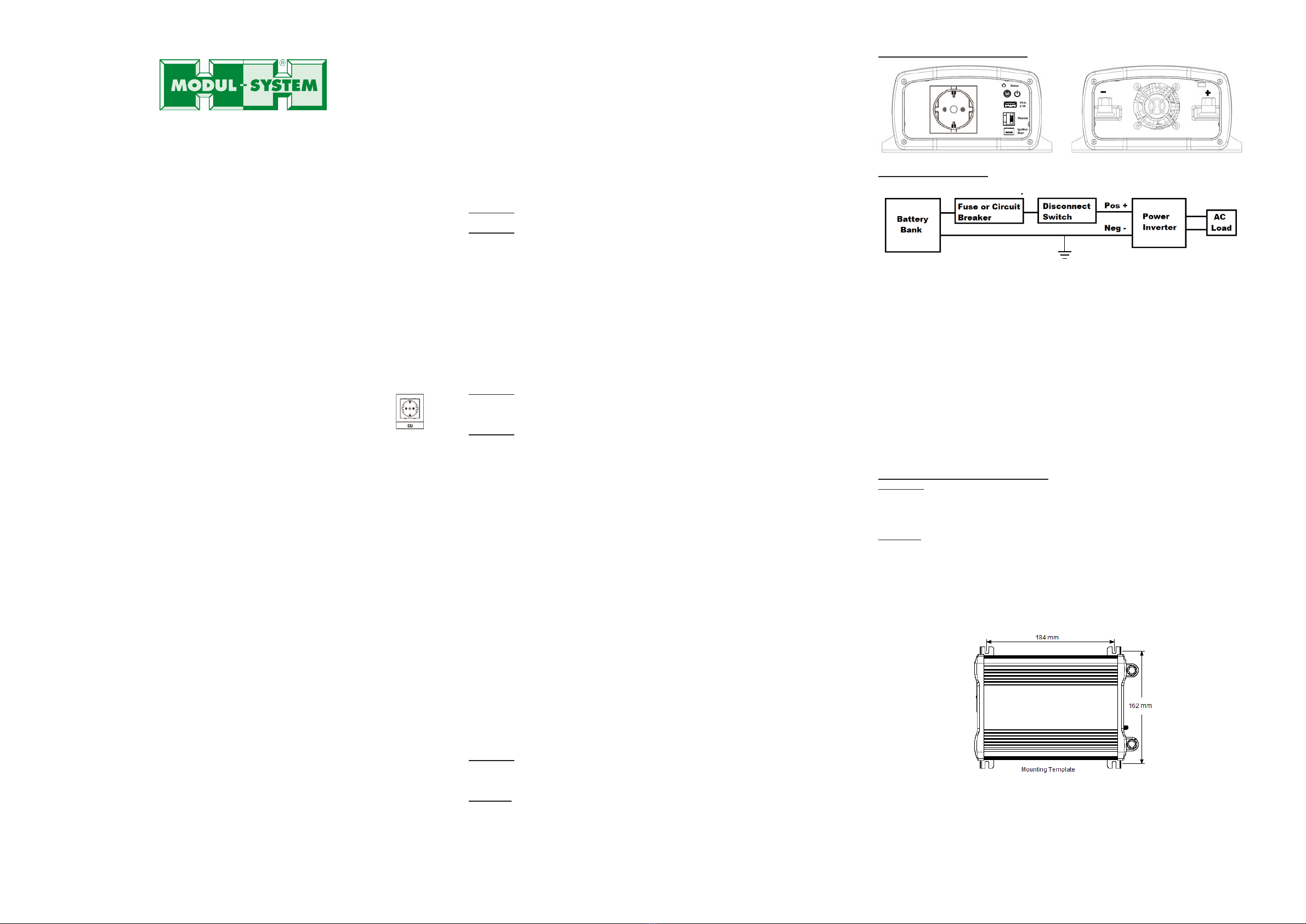
• Connect the other end of the positive DC input cable to one of the terminals of the
Disconnect Switch.
• Connect a DC input cable between the other terminal of the Disconnect Switch and one
side of the terminal of the fuse holder.
• Connect a DC input cable between the other terminal of the fuse holder and the battery
positive terminal.
• Install the selected fuse to the fuse holder.
• Turn Disconnect Switch to ON position.
Remote Switch (optional) Connection:
• The unit comes with a Remote port and an optional Modul-System ’Remote Switch’
accessory (21000-03) can be used to turn unit On and OFF remotely. To install the
‘Remote Switch’, just connect the switch’s RJ12 plug to the RJ12 ‘Remote’ port located at
the Front AC panel of the Power inverter. Please note polarity when connecting the plug.
• The Power ‘On/Off’push button on the remote shares the same function as the green
‘On/Off’ button on the main unit.
• With ‘Power Save’ Function set to OFF (default), the ‘Power’ indicator will remain solid ON
when AC Output Power is available and will be OFF when the unit has shutdown.
• With ‘Power Save’ Function set to ON, the ‘Power’ indicator will be flashing when AC
Output Power is available and will be OFF when the unit has shutdown.
• Please note that the Modul-System Power Inverter will not work with the digital
wiring and control system Modul-Connect with the ‘Power Save’ Function set to ON.
Use of the Ignition Start Function on unit:
• An ‘Ignition Start’ port is located at the Front AC Panel of the unit using a 6.3mm width
female spade terminal. This port is used for turning the unit ON and OFF using a +12V
signal. An insulated female connector is required to connect to the port.
• Connecting to +12V will turn ON the unit and removing the +12V signal will turn it OFF.
• This +12V connection should be fused at its source with a minimum 2A fuse.
Power Inverter Test after installation:
• Press and hold the green ‘On/Off’ button on the unit to turn ON the unit.
• Check that the ‘Status’ indicator turns to solid green.
• Plug in a small AC load like a 40W table lamp or small appliance to the AC socket to verify
AC is available.
• The unit is successfully installed and functioning properly.
4. UNIT OPERATION
WARNING: RISK OF EQUIPMENT DAMAGE
Do not connect an AC power source like utility power or generator to the AC outlets of the unit.
Turn ON and OFF the unit
• Press and hold the green ‘On/Off’ button for about a second to turn ON the unit and
‘Status’ indicator will turn on.
• Press again the green ‘On/Off’ button to turn OFF the unit and the ‘Status’ indicator will
turn off.
Understanding the ‘Power Save’ function
The unit can pre-set with ‘Power Save’ function ON or OFF. If unit is turned ON with ‘Power
Save’ function pre-set to ON, with >10W AC load connected to the unit, the unit will provide
continuous AC Output and with <10W AC Load connected to the unit or with AC Load
changing from >10W to < 5W, the AC Output will change from continuous to pulsing AC
Output every 5 seconds.
The unit is default set to ‘Power Save’ OFF. To change the ‘Power Save’ function from OFF
to ON or switch back from ON to OFF, press and hold the green ‘On/Off’button for more
than 5 second until the ‘Status’ light quickly flashes three times and the alarm beeps for
more than 2 seconds.
Understanding the ‘Status’ indicator
Function
‘Status’ Indicator
Condition
Power
Save
Function
‘OFF’
Solid Green
Unit is normal and continuous AC Output is
available
Solid Green with alarm
beep every 2 seconds
Unit is detected with either DC Over/Under
Voltage or Over Temperature warning and
continuous AC Output is still available
Power
Save
Function
‘ON’
Flashing Green
Unit is normal and AC Load connected is
>10W
Flashing between Amber
and Red
Unit is normal and AC Load connected is
<10W or AC Load connected is reduced from
>10W to < 5W
Flashing Green and alarm
beep every 2 seconds
Unit is detected with either DC Over/Under
Voltage or Over Temperature warning and
AC Load connected is > 10W
Flashing between Amber
and Red and alarm beep
every 2 seconds
Warning detected with either DC Over/Under
Voltage or Over Temperature
AC Load connected is <10W or AC Load
connected is reduced from >10W to <5W
Power
Save
Function
is either
Solid Red with alarm
beep every second
No AC Output as unit had shut down due to
either DC Over/Under Voltage or AC Output
Overload or Over Temperature occurs.
See more details on “Understanding the
‘ON’ or
‘OFF’
Warning and Shutdown Condition” in this
manual
Understanding the Warning and Shutdown Condition
Over Temperature Warning: Unit internal temperature is high. Unit requires better
ventilation.
DC Over Voltage Warning: DC Input Voltage is high and close to the over-voltage
shutdown limit. Checking the battery voltage.
DC Under Voltage Warning: DC Input Voltage is low and is close to the under-voltage
shutdown limit. Checking on battery voltage or battery connection is required.
Over Temperature Shutdown: Reduce the AC load and provide more ventilation to the unit.
Unit will automatically restart when the internal temperature of the unit cools down.
DC Over Voltage Shutdown / DC Under Voltage Shutdown: Check the battery voltage in
the first 30 seconds, AC Output will resume when battery voltage is corrected to be within
the unit’s operating range. If the battery voltage shutdown condition is ignored, the unit will
latch OFF completely after 30 seconds and restart the unit using green ‘On/Off’button is
required after the battery voltage is corrected.
AC Output Overload Shutdown: Check AC Load connected to the unit. AC Output is short
circuited or AC Power draw by the load is beyond the unit’s limit. The indicator and alarm
will beep for about 30 seconds before it is latched OFF completely. Restarting the unit
using the green ‘On/Off’button is required after the AC Load condition is corrected.
USB Port on unit
With unit on, 2.1A 5V USB is provided on the 5V USB port. This can be used to charge 5V
USB Powered devices.
Understanding the Fan Operation
The fan on the unit is internal temperature activated. It will automatically turn on when AC
output power exceeds the pre-set values (~ 200W) and turn off when AC output power is
reduced to 150W. It will also automatically turn on when it senses the internal components
have reached to around 80°C and turn off when temperature drops to below 60°C.
AC Load on Power Inverter
Although the Power Inverter can provide high surge power (up to two times the rated output
power), some appliances may still trigger on the unit protection system during start up or
surge period. A higher power inverter is required for those appliances.
Estimated Run time on Load
Following run time is an estimate based on using a 12V-120AH battery bank. Actual runtime
may vary.
Load
Consumption
Estimate Run time
Cordless Phone
5W
150 hrs
Clock / Radio
8W
100 hrs
Table Lamp
40W / 60W
27 hrs / 18 hrs
Small Freezer (8.8 cu. ft.)
80W
15 hrs
20” LCD TV
100W
11.5 hrs
Flood Light
500W
1 hr
Sump Pump (1/2 hp)
350W
Not applicable (start-up surge too high)
5. TROUBLESHOOTING
Problem
Symptom
Solution
No AC output and
‘Status’ light is OFF
The unit is off
Turn unit ON
No power to
inverter
Check fuse or if the Disconnect switch (if
installed) is either blown or turned OFF
‘Status’ indicator is
in green or flashing
between amber and
red (alarm beeps
every 2 seconds)
Unit has detected
a warning and is
going to shutdown
Verify the warning condition and make
adjustment. See “Understanding the
‘Status’ indicator”in this manual
‘Status’ indicator is
in red (alarm beeps)
Unit has shut
down
Check unit condition and make correction.
See “Understanding the ‘Status’
indicator” in this manual
6. SPECIFICATIONS
Note: Specifications are subject to change without notices.
Specifications
21060-03
Inverter
AC Output Power
600 Watt
AC Output Current
2.6A
AC Surge Power
1200 Watt
AC Output Voltage
230Vac / 50Hz
AC Output Waveform
True Sinewave (<5% THD)
DC Input Voltage
12.5 VDC
No Load Current (Power Save OFF)
< 0.8 A
No Load Current (Power Save ON)
< 0.2 A
DC Operating Range
10.5 – 15.9 VDC
Under Voltage Alarm
11.0 VDC
Under Voltage Alarm Recovery
11.3 VDC
Under Voltage Shutdown
10.5 VDC
Under Voltage Recovery
12.0 VDC
Over Voltage Shutdown
15.9 VDC
Over Voltage Recovery
15.0 VDC
Power Save OFF
>10W
Power Save OFF to ON
~ 5W
AC Output Socket
EU
Safety and Environmental
Agency Markings
CE LVD, EMC,
Operating Temp.
0℃to 40℃
Storage Temp.
-20℃to 60℃
Relative Humidity
5 - 90% non-condensing
Operating Altitude
Up to 2000 m above sea level
Weights and Dimensions
Weights
2.0 kg
Dimensions
237 x 175 x 89 mm
7. WARRANTY
Two Year Limited Warranty
The limited warranty program is the only one that applies to this unit, and it sets forth all the
responsibilities of Modul-System. There is no other warranty, other than those described
herein. Any implied warranty of merchantability of fitness for a particular purpose on this unit is
limited in duration to the duration of this warranty.
This unit is warranted, to the original purchaser only, to be free of defects in materials and
workmanship for two years from the date of purchase without additional charge. The warranty
does not extend to subsequent purchasers or users.
Manufacturer will not be responsible for any amount of damage in excess of the retail
purchase price of the unit under any circumstances. Incidental and consequential damages are
specifically excluded from coverage under this warranty.
This warranty does not apply to damage to units from misuse or incorrect
installation/connection. Misuse includes wiring or connecting to improper polarity power
sources.
Return/Repair Policy:
If you are experiencing any problems with your unit, please contact our customer service
department at info@modul-system.com or phone +46 31 746 87 00 before returning product.
After speaking to a customer service representative, if products are deemed non- working or
malfunctioning, the product may be returned to Modul-System within 30 days of original
purchase. Any defective unit that is returned to manufacturer within 30 days of the date of
purchase will be replaced free of charge.
If such a unit is returned more than 30 days but less than two years from the purchase date,
manufacturer will repair the unit or, at its option, replace it, free of charge. If the unit is repaired,
new or reconditioned replacement parts may be used, at manufacturer’s option. A unit may be
replaced with a new or reconditioned unit of the same or comparable design. The repaired or
replaced unit will then be warranted under these terms for the remainder of the warranty period.
The customer is responsible for the shipping charges on all returned items.
Limitations:
This warranty does not cover accessories, such as adapters and batteries, damage or defects
result from normal wear and tear (including chips, scratches, abrasions, discoloration or fading
due to usage or exposure to sunlight), accidents, damage during shipping to our service facility,
alterations, unauthorized use or repair, neglect, misuse, abuse, failure to follow instructions for
care and maintenance, fire and flood.
If your problem is not covered by his warranty, contact our Customer Service Department at
info@modul-system.com or +46 31 746 87 00 for general information if applicable.
Service Contact Information
Email: info@modul-system.com
Phone: +46 31 746 87 00
www.modul-system.com

This manual suits for next models

1

Other Modul-System Inverter manuals

Modul-System True Sinewave Series User manual

Modul-System

Modul-System True Sinewave Series User manual

Popular Inverter manuals by other brands

Cosuper CPT Series user manual

Cosuper

Cosuper CPT Series user manual

Samil Power SolarRiver 1100TL-S manual

Samil Power

Samil Power SolarRiver 1100TL-S manual

Kostal PIKO 36 EPC operating manual

Kostal

Kostal PIKO 36 EPC operating manual

Makita EG SERIES Instructions for use

Makita

Makita EG SERIES Instructions for use

OmniPower OHY1P4805 user manual

OmniPower

OmniPower OHY1P4805 user manual

Wooh PPG-280 user manual

Wooh

Wooh PPG-280 user manual

Bioenno Power BLF-1260L Guide

Bioenno Power

Bioenno Power BLF-1260L Guide

WARRIOR GENERATORS LDG4600E owner's manual

WARRIOR GENERATORS

WARRIOR GENERATORS LDG4600E owner's manual

Soltech SOLPORT 15W installation manual

Soltech

Soltech SOLPORT 15W installation manual

Growatt SPF 5000TL HVM user manual

Growatt

Growatt SPF 5000TL HVM user manual

ABB REACT-3.6-TL product manual

ABB

ABB REACT-3.6-TL product manual

Cobra CPI 875 operating instructions

Cobra

Cobra CPI 875 operating instructions

Generac Power Systems Guardian 005324-1 owner's manual

Generac Power Systems

Generac Power Systems Guardian 005324-1 owner's manual

SolarCity solarZero manual

SolarCity

SolarCity solarZero manual

Anker SOLIX Solarbank E1600 user manual

Anker

Anker SOLIX Solarbank E1600 user manual

Siemens SED2 Series Getting started guide

Siemens

Siemens SED2 Series Getting started guide

Mitsubishi FREQROL Z200-U instruction manual

Mitsubishi

Mitsubishi FREQROL Z200-U instruction manual

Viessmann 5216 Operation manual

Viessmann

Viessmann 5216 Operation manual

manuals.online logo
manuals.online logoBrands
  • About & Mission
  • Contact us
  • Privacy Policy
  • Terms and Conditions

Copyright 2025 Manuals.Online. All Rights Reserved.