User Instructions
Should you nd your equipment is no longer of use,
please dispose of in a responsible manner. Please
contact Modulift if you need further guidance
© Copyright 2017 Modulift.
All rights reserved.
MOD CLS
MOD CLS US JULY 2017
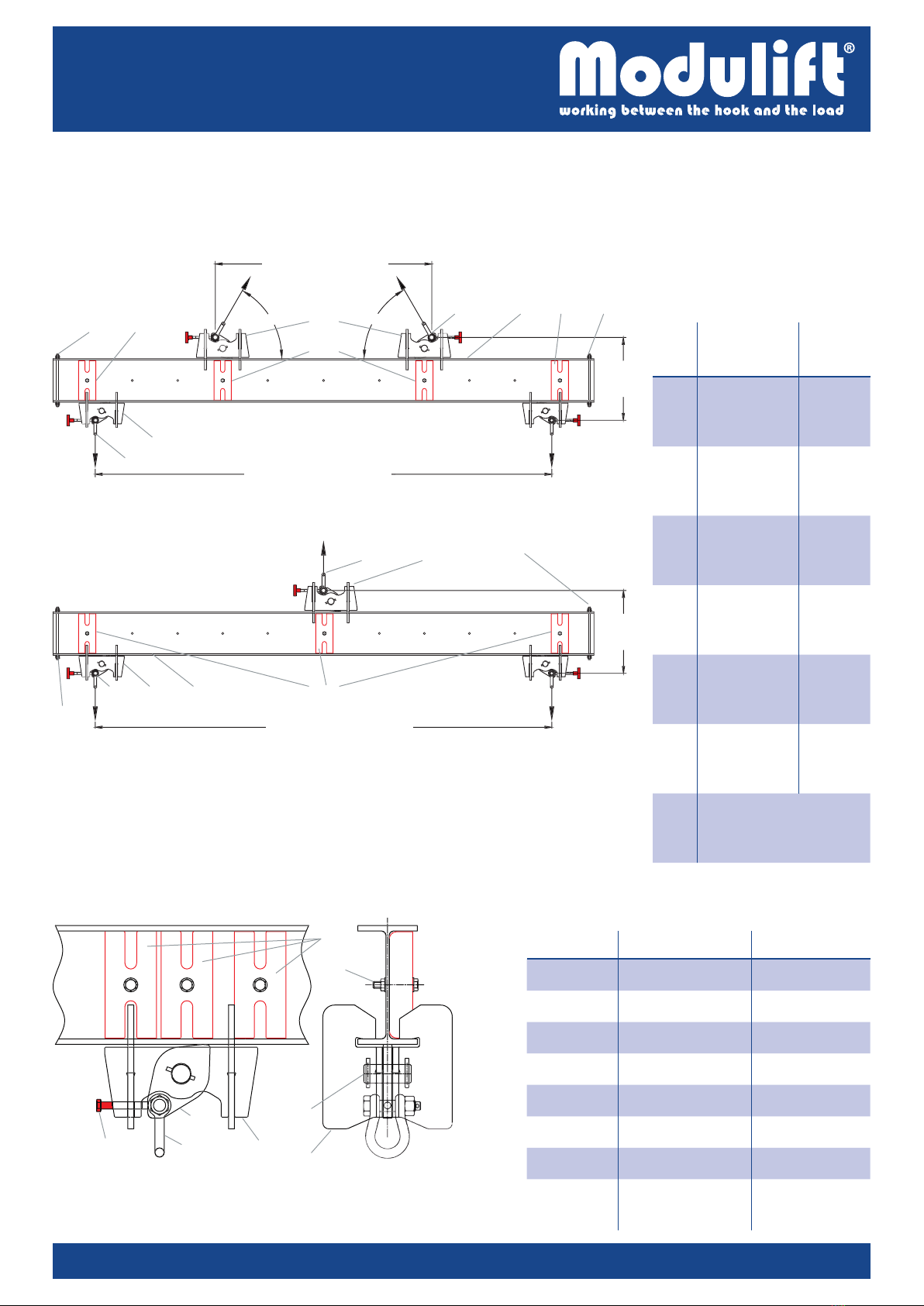
Assembly Procedure
Each lifting beam clamp will be supplied fully assembled.
Individual clamps are not to be dismantled.
Remove stopper bolts and push each lifting beam clamp
through the open-end section of the beam, ensuring that
the lug plate is orientated the correct way as shown in Fig. 4
Replace stopper bolts and nuts on top and bottom anges
at each end of the beam. Tighten to a torque of 30 lbf.ft
For additional safety, always ensure the red locking bolt
on each clamp is tightened to a torque of 30 lbf.ft and the
clamp is secure, once in the correct position on the beam
for your desired lifting conguration.
Always t at least one red safety stop to each clamp (see Fig.
3). Tighten bolt to a torque of 30 lbf.ft before lifting. For ease
of visibility, t all red safety stops to one side of the beam
Always ensure the 6.5t Lifting Beam Clamps are tted to
the top of the beam and the 4.75t Lifting Beam Clamps are
tted to the bottom of the beam.
If in any doubt please contact Modulift.
Do’s & Don’ts
Always have the safety stopper bolts or studs tightened with
nuts on both top and bottom anges and at both ends of the
beam before commencing any lifts.
Do not hang any loads directly from the beam section, always
lift from shackles on the beam clamps.
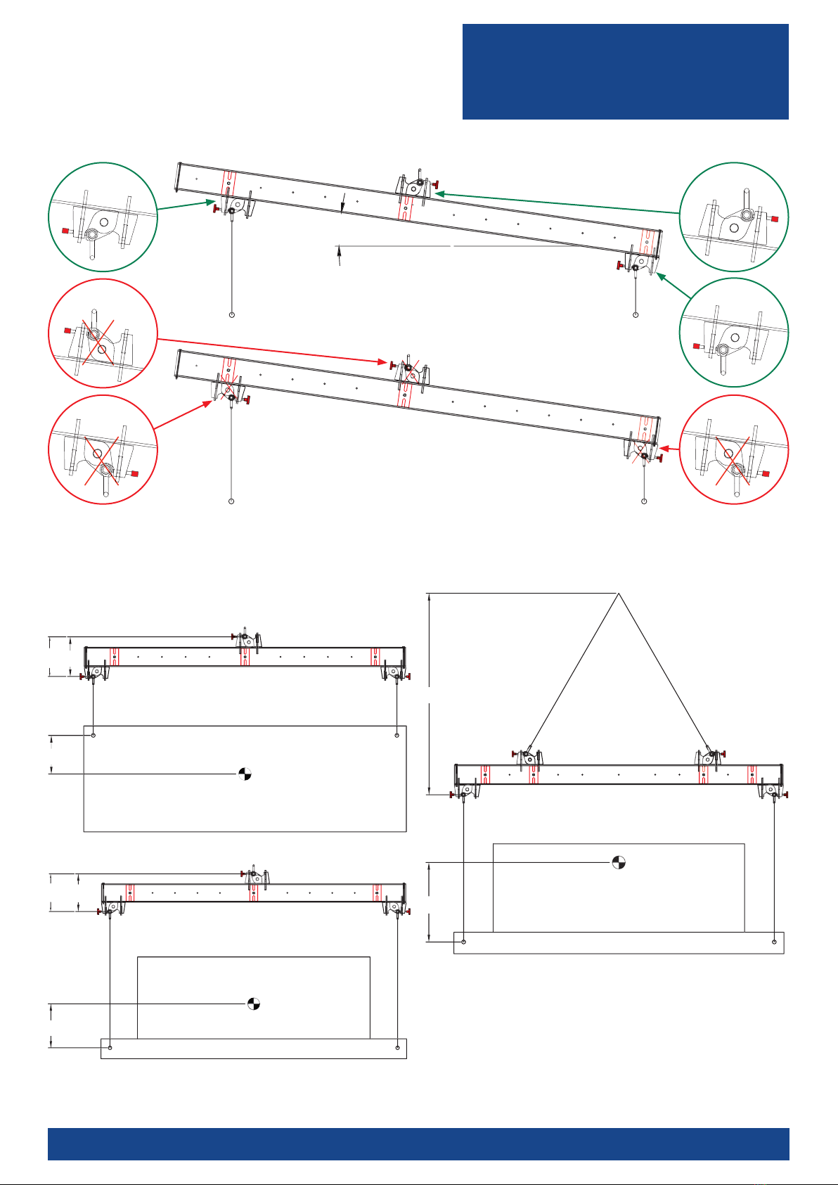
Do ensure that the clamp lug plate is always being pulled
towards the body of the clamp, never away from the body of
the clamp (see Fig. 4 and Fig. 5).
Do ensure the red locking bolt on each clamp is tightened
to a torque of 30 lbf.ft prior to any lift.
Do ensure at least one red safety stop is tted to each clamp
(see Fig. 3). For arrangement (iii) Fig.3, always check red
safety stop is attached to the nearest beam hole to the clamp.
Tighten bolt to a torque of 30 lbf.ft prior to any lift. For ease of
visibility, t all red safety stops to one side of the beam
Do ensure that the lift is stable. Never carry out unstable lifts.
Do ensure that the load and the beam (either loaded
or unloaded) both lift level by positioning the bottom
clamps in the correct location (depending on clamp lug plate
orientation, a maximum of 6 degrees of tilt is permitted).
Never stand beneath the suspended load or lifting beam
(either loaded or unloaded).
Do ensure that the beam ange and the clamps are free of
grease or excessive water where they clamp together.
Check that there is no
deformation or distortion
on the clamps before any
lift. In case of deformation or distortion,
the relevant part must be discarded and
replaced. Always check and ensure
that the arms of the collar plates are
parallel and not deformed (refer to Fig. 6).
Check collar
plate arms are
parallel and
not deformed
Fig. 6 – Collar plate
WARNING!
Personnel using this system should be suitably trained,
competent and have a clear understanding of Safe
Slinging procedures.
The use of Modulift equipment must be in accordance with
the procedures laid down in ‘ASME B30.20 – 2013’.
Never exceed stated beam WLL (adhere to Table 3 WLL for
conguration used) or clamps WLL (see MOD CLS specication).
The top sling length is critical to the safe use of the beam
when used on the semi-spreader conguration. Do not
have less than 60° BSA sling angles.
Ensure that clamp lug plates are always being pulled
towards the body of the clamp (as shown in Fig. 4), never
away from the body of the clamp (as shown in Fig. 5).
Always ensure the red locking bolt on each clamp is
tightened to a torque of 30 lbf.ft before lifting.
Always t at least one red safety stop to each clamp (see Fig.
3). Tighten bolt to a torque of 30 lbf.ft before lifting. For ease
of visibility, t all red safety stops to one side of the beam.
Ensure that the beam is lifting level whenever possible.
Never allow the beam to tilt more than 6 degrees from
the horizontal plane (Please refer to LEEA COPSULE). In
case of tilt, ensure that the clamp lug plates are orientated
so that the tilt angle pulls the clamp lug plate towards the
body of the clamp, never away from the body of the clamp.
Always ensure that the lift is stable. Please note that for a
lifting beam conguration the height increment between
beam pivoting points shall not exceed 19.7", as shown in
Fig. 2 (1 top lug). If in any doubt please contact Modulift.
Modulif
t
UK
L
td
tel: 011 44 1202 621511 email: [email protected] www.modulift.com Page 2 of 4Table 3 – WLL v Span (in metric tons)
Semi-Spreader conguration (2 top lugs, Fig. 1)
Lifting Beam conguration (1 top lug, Fig. 2)
WLL (t) A – Top Clamp Span (ft)
<1½ 3 6½ 10 13 16 19½
B – Bottom Span (ft)
<1½ 8.5 8 7 3.5 2 1.25 0.8
38 8.5 8 4.5 2.5 1.5 0.9
6½ 7.5 8 8.5 7 3.25 1.75 1
10 4.25 5.5 8 8.5 5.25 2.5 1.25
13 2.25 3 4.5 8 8 4 1.75
16 1.25 1.75 2.25 3.75 7 7.5 2.5
19½ 0.9 1 1.25 2 2.75 4.25 5.25
If your exact spans are not noted in the table, then please round the
spans up or down to the values that will give you the lowest SWL.
Contact Modulift if you need a specic WLL value for a specic span or
arrangement not covered on the tables above.
B – Bottom Span (ft) ≤ 6½ ≤ 10 ≤ 13 ≤ 16 ≤ 19½
WLL (in metric tons) 6.2 3.75 2.25 1.25 0.8
Fig. 4 – Correct orientation
of lug plates
Fig. 5 – Incorrect orientation
of lug plates
60°
Minimum