Pump unit to deliver fresh hot domestic water (DHW) ModvFresh 2 T
Rev.0 - 18/02/2021
Page 4 of 7
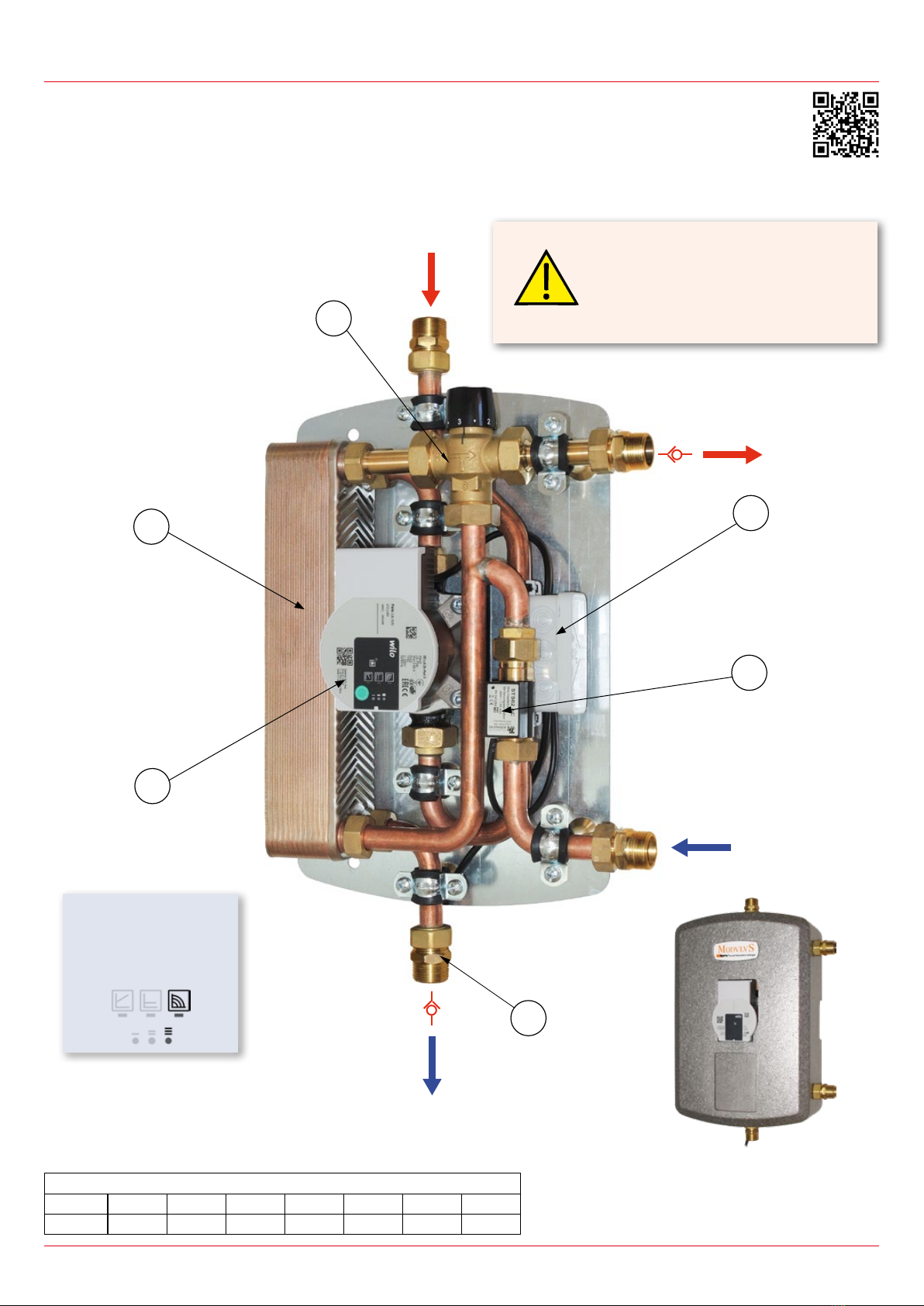
PERICOLO DI USTIONI
Per impedire ustioni all’utenza, non
superare mai i 60°C di temperatura
dell’acqua erogata.
Minimum delivery capacity
To ensure a constant temperature of the DHW delivered, a minimum ow of delivery capacity is required. In the following table there is
an example of delivery with a cold water temperature of 10°C on the supply: minimum deliveries are shown necessary to ensure stability
at 45°C requested by the user, making various assumptions of water temperatures provided by the tank.
Water temperature on supply
from the tank
Minimum capacity for the model
ModvFresh 2 T 50 kW
Minimum capacity for the model
ModvFresh 2 T 70 kW
55 °C 2 l/min 2,5 l/min
60 °C 2,5 l/min 3 l/min
65 °C 3 l/min 3 l/min
70 °C 3 l/min 3,5 l/min
75 °C 3,5 l/min 3,5 l/min
80 °C 4 l/min 4 l/min
Calculation of performances
It is also possible to download an excel le from the site www.modvlvs.com dedicated to the calculation of the peformances
of the ModvFresh 2 T unit from where you cen get: output power, time of delivery, the overall delivery capacity and recovery
time of the temperature in the tank.
Suggestions / Remarks on the delivery capacity
The temperature into the storage tank must be almost 10K higher than the desired
temperature of the domestic water. Higher dierences of temperature allow to extend the
delivery time of the hot water. In presence of calcareous water we recommend not to
exceed the temperature of 70°C (supply from the storage tank) to avoid limescale into the
secondary side of the plate exchanger, in case put a thermostatic valve (Pict.1).
Diagrams of the pump unit performances
The following diagrams relate the user’s ow rate and the supply temperature to the buer storage tank, according to the requested
temperature of DHW. This allows to identify the minimum supply temperature needed to supply DHW at a required temperature and
ow. Vice versa it is also possible to x which is the maximum usable ow at the selected DHW temperature, at the available supply
temperature. Performances are also due to the inlet temperature of the cold water from the water supply system; diagrams show three
possibilities with inlet water at 5°C, 10°C and 15°C.
How to read the diagrams
Example 1, shown in the next page (ModvFresh 2 T 50 kW, inlet at 10°C). In this case a DHW ow of 12 l/min at a temperature of 45°C
is required. Crossing the desired DHW temperature curve, it follows that the supply from the buer storage tank must be almost 51,7°C.
Example 2, shown in page 6 (ModvFresh 2 T 70 kW, inlet at 10°C). This is the case in which the supply from the buer storage tank cannot
go over 56°C and we want to see what can be the maximum suppliable temperature at the DHW of 45°C. Crossing the desired DHW
temperature curve, it follows that the ow cannot be over 19,3 l/min.