Mounting plates,
CI distribution boards
7
04/97 AWB 27-1287-GB
cable clip must sit snugly around the entire
circumference of the cable screen.
햶Connect the external protective circuit (potential
to earth) to the control cabinet reference potential
(internal protective conductor bar) with a large-
area and low-impedance connection.
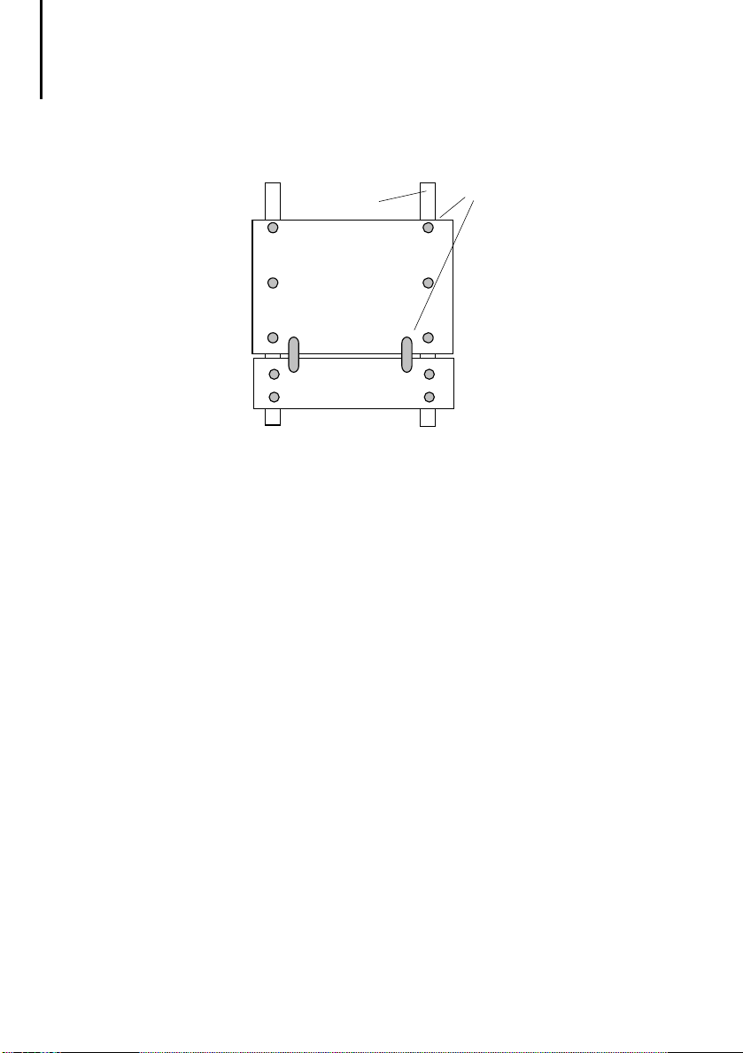
Mounting plates,
CI distribution boards
You should use mounting plates as your base.
Connect the mounting plates to the control cabinet
with a low-impedance connection.
Use mounting plates made of galvanized sheet steel
(no enamelling).
The CI distribution board must be fitted with a
galvanized mounting plate. The mounting plate of the
CI distribution board forms the reference potential
surface.
Make sure that connecting points are protected
against corrosion.
Mounting plates must be connected not only to each
other but also to the internal protective circuit with
low-impedance and large-area connections so as to
form one overall reference potential surface. Here
you should connect the mounting plates, mounting
sub-plates, metal device plates to the cabinet
earthing system as often as possible.
Protect the all chassis earth connections against
corrosion.
Total insulation is cancelled by implementing the
provisions of “Reference potential surface”.