x
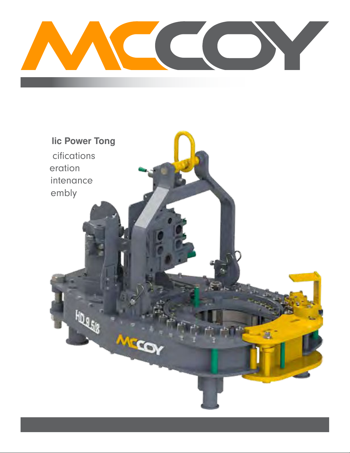
HD9625 9-⅝” - 22K Tong
TecHnical Manual
Tables ofconTenTs
SECTION FIVE: PARTS AND ASSEMBLIES
Gear Train ........................................................................................................................................................................ 5.4
Rotary Idler Assembly ...................................................................................................................................................... 5.6
Pinion Idler Assembly....................................................................................................................................................... 5.8
Pinion Assembly............................................................................................................................................................... 5.10
Clutch Assembly............................................................................................................................................................... 5.12
Manual Shifter Assembly.................................................................................................................................................. 5.14
Cage Plate Assembly ....................................................................................................................................................... 5.16
....................................................................................................................................................... 5.18
Hydraulic Supports ........................................................................................................................................................... 5.20
Motor & Motor Mount........................................................................................................................................................ 5.22
..................................................................................................................................................................... 5.24
Door Assembly (First-Generation Safety Door)................................................................................................................ 5.26
Door Assembly (Second-Generation Safety Door) .......................................................................................................... 5.28
Rigid Sling Assembly........................................................................................................................................................ 5.30
SECTION SIX: TORQUE MEASUREMENT
........................................................................................................................ 6.3
............................................................................................................................................. 6.7
6.C.1 Inspection..................................................................................................................................................... 6.8
6.C.2 Fluid Recharge............................................................................................................................................. 6.8
............................................................................ 6.8
6.C.4 Repair And Calibration ................................................................................................................................. 6.9
SECTION SEVEN: OEM DOCUMENTATION
LIST OF ILLUSTRATIONS
IllustratIon 1.a.1: HD9625 Power tong .................................................................................................................................. 1.3
IllustratIon 1.a.2: HD9625 Power tong DImensIons................................................................................................................. 1.4
IllustratIon 2.B.1: major ComPonent IDentIfICatIon 01.............................................................................................................. 2.3
IllustratIon 2.B.2: major ComPonent IDentIfICatIon 02.............................................................................................................. 2.4
IllustratIon 2.B.3: major ComPonent IDentIfICatIon 03.............................................................................................................. 2.5
IllustratIon 2.a.1: slIng angle ................................................................................................................................................. 2.6
IllustratIon 2.D.1: lIft CylInDer & sPrIng Hanger InstallatIon................................................................................................. 2.9
IllustratIon 2.D.2: lIft CylInDer HyDraulIC ConneCtIon ............................................................................................................ 2.10
IllustratIon 2.e.1: HyDraulIC sCHematIC .................................................................................................................................... 2.12
IllustratIon 2.e.2: HyDraulIC ComPonent IDentIfICatIon 01........................................................................................................ 2.13
IllustratIon 2.e.3: HyDraulIC ComPonent IDentIfICatIon 02........................................................................................................ 2.14
IllustratIon 2.e.4: HyDraulIC ComPonent IDentIfICatIon 03........................................................................................................ 2.14
IllustratIon 2.e.5: HyDraulIC ComPonent IDentIfICatIon 04........................................................................................................ 2.15
IllustratIon 2.e.6: HyDraulIC ComPonent IDentIfICatIon 05........................................................................................................ 2.15
IllustratIon 2.e.7: HyDraulIC ComPonent IDentIfICatIon 06........................................................................................................ 2.15
IllustratIon 2.e.8: HyDraulIC ConneCtIons 01 ........................................................................................................................... 2.16
IllustratIon 2.e.9: HyDraulIC ConneCtIons 02 ........................................................................................................................... 2.16
IllustratIon 2.f.1: jaw rePlaCement ......................................................................................................................................... 2.19
IllustratIon 2.H.1: tong susPensIon relatIve toaxIal Centre ................................................................................................. 2.21
IllustratIon 2.H.2: tong susPensIon relatIve tovertICal Centre ............................................................................................ 2.21
IllustratIon 2.g.3: tong levelIng (sIDe-to-sIDe) ...................................................................................................................... 2.22
IllustratIon 2.g.4: tong levelIng (front-to-rear) .................................................................................................................. 2.23
IllustratIon 2.H.1: tong rotatIon Control valve ..................................................................................................................... 2.24
IllustratIon 2.H.2: tong lIft CylInDer Control valve .............................................................................................................. 2.25
IllustratIon 2.H.3: tong lIft CylInDer neeDle valve................................................................................................................. 2.25
IllustratIon 2.H.4: tong motor sPeeD Control valve .............................................................................................................. 2.26
IllustratIon 2.H.5: tong manual sHIft Control ........................................................................................................................ 2.27
IllustratIon 2.I.1: master lIftIng lInk ....................................................................................................................................... 2.29
IllustratIon 2.I.2: settIng BaCkIng PIn to“make-uP” PosItIon.................................................................................................... 2.30
IllustratIon 2.I.3: lIft CylInDer Control - raIse ....................................................................................................................... 2.30
IllustratIon 2.I.4: oPenIng tong Door ...................................................................................................................................... 2.31
IllustratIon 2.I.5: motor Control - make-uP ............................................................................................................................. 2.31
IllustratIon 2.I.6: motor Control - releasIng jaws .................................................................................................................. 2.32
IllustratIon 2.I.7: lIft CylInDer Control - lower...................................................................................................................... 2.32
IllustratIon 2.I.8: settIng BaCkIng PIn to“Break-out” PosItIon................................................................................................ 2.33
IllustratIon 2.I.9: rotatIon Control - Break-out ..................................................................................................................... 2.34
IllustratIon 2.I.10: releasIng tong jaws followIng Break-out & un-tHreaDIng ........................................................................ 2.34
IllustratIon 2.I.11: lowerIng tong usIng lIft CylInDer Control............................................................................................... 2.35
Continued on next page...