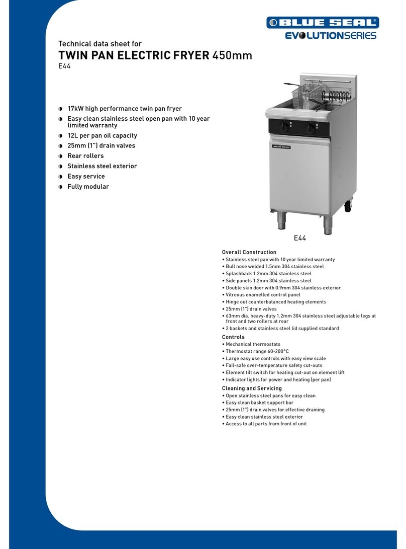
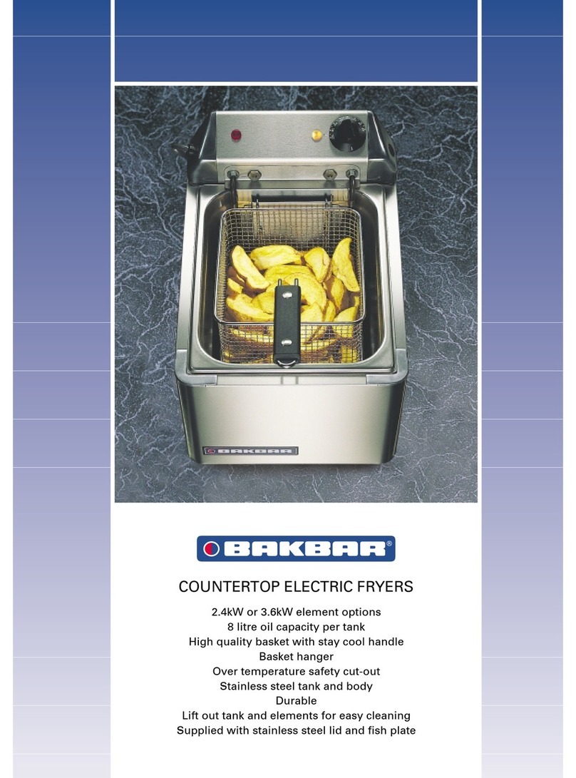
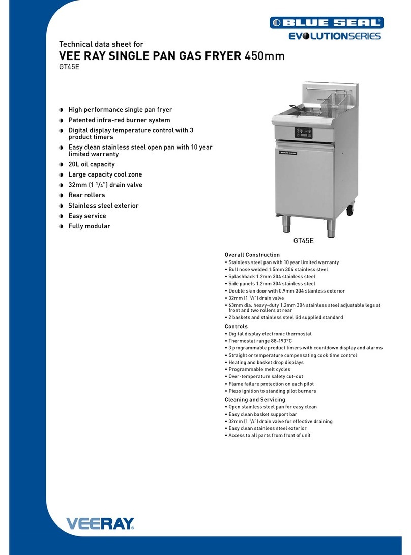
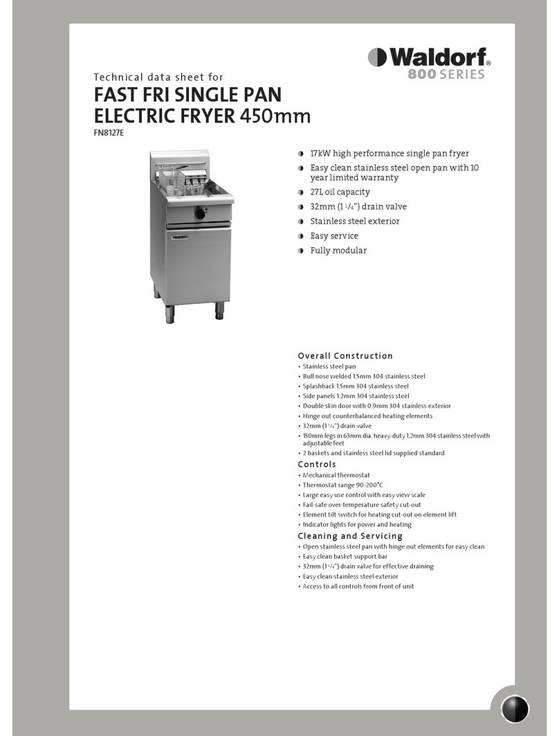
Moffat Cobra User manual

Amendment 4
2 June 2015
Service Manual
400mm - Gas Fryers
Cobra - CF2
Waldorf - FN8118G
Blue Seal - GT18
FastFri - FF18

The reproduction or copying of any part of this manual by any means whatsoever is strictly forbidden unless authorized previously in writing
by the manufacturer.
In line with policy to continually develop and improve its products, Moffat Ltd. reserves the right to change the specifications and design
without prior notice.
© Copyright Moffat Ltd. June 2015.
MANUFACTURED BY
Moffat Limited
Rolleston 7675
New Zealand
INTERNATIONAL CONTACTS
AUSTRALIA
Moffat Pty Limited
Main Office: (tel) (03) 9518 3888
(fax) (03 9518 3833
Service: (tel): 1800 622 216
Spares: (tel): 1800 337 963
Customer Service: (tel): 1800 335 315
(fax): 1800 350 281
NEW ZEALAND
Moffat Limited
Web: www.moffat.co.nz
E.Mail: [email protected]
Main Office: (tel): 0800 663328
UNITED KINGDOM
Blue Seal
Web: www.blue-seal.co.uk
E.Mail: [email protected]
Sales: (tel): 0121 327 5575
(fax): 0121 327 9711
Spares: (tel): 0121 322 6640
(fax): 0121 327 9201
Service: (tel): 0121 322 6644
(fax): 0121 327 6257
REST OF WORLD
Moffat Limited
Web: www.moffat.co.nz
E.Mail: [email protected]

Contents List
Model Numbers Covered in this Manual
Cobra - CF2
Waldorf - FN8118G
Blue Seal - GT18
FastFri - FF18
1. Specifications ..................................................................................................................... 2
2. Installation ......................................................................................................................... 7
Installation Requirements
Unpacking
Location
Clearances
Assembly
Gas Connection
3. Operation .......................................................................................................................... 10
Fryer Controls
4
.
Fault Finding ..................................................................................................................... 11
Fryer Faults
Fault Diagnosis
5. Circuit Schematic.............................................................................................................. 15
Gas Circuit Schematic
6
.
Parts Replacement ........................................................................................................... 16
Replacement
Adjustment / Calibration
7. Accessories.................................................................................................................... 21
8. Exploded Parts Listings ................................................................................................ 22
9. Service Contacts ........................................................................................................... 34
Appendix A - Gas Type Conversion ........................................................................................ 35
ALL INSTALLATION AND SERVICE REPAIR WORK MUST BE CARRIED OUT BY QUALIFIED PERSONS ONLY.
IMPROPER INSTALLATION, ALTERATION, ADJUSTMENT, MAINTENANCE OR SERVICE MAY CAUSE PROPERTY
DAMAGE, INJURY OR DEATH.
ENSURE SUPPLY IS SWITCHED OFF BEFORE SERVICING.
ALWAYS TEST AFTER SERVICE REPAIRS HAVE BEEN CARRIED OUT.
WARNING:

1 Specifications
2
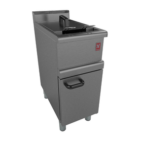
Cobra CF2 - 400mm Gas Fryer (Single Tank - 18Ltr).

Specifications 1
3
Waldorf FN8118G - 40mm Gas Fryer (Single Tank - 18Ltr).

1 Specifications
4
Blue Seal GT18 - 400mm Gas Fryer (Single Tank - 18Ltr).

Specifications 1
5
FastFri FF18 - 400mm Gas Fryer (Single Tank - 18Ltr).

1 Specifications
6
Gas Supply (Non-UK Models)
FF18 FN8118G GT18
Oil Capacity 18ltrs
12kg / 32lbs
18ltrs
12kg / 32lbs
18ltrs
12kg / 32lbs
Useable Internal Dimensions of
Tank (width x length) 305mm x 380mm 305mm x 380mm 305mm x 380mm
Useable Depth of Oil 95mm 95mm 95mm
CF2
18ltrs
12kg / 32lbs
305mm x 380mm
95mm
Combustible Surface Non-Combustible Surface
Rear 50mm 0mm
Left-Hand Side 50mm 0mm
Right-Hand Side 50mm 0mm
Top * 610mm 610mm
Front ** 600mm 600mm
* Top Clearance - is from the flue outlet to any above surface.
** Front Clearance - is in order to facilitate easy operation, drainage and servicing of the appliance.
Installation Clearances
Tank Capacity
Gas Supply (UK Models)
Natural Gas (G20) Propane (G31)
Heat Input (nett) 22.5 kW 22.5 kW
Gas Rate 2.26 m3/hr 1.75 kg/hr
Supply Pressure 20 mbar 37 mbar
Burner Operating Pressure 9.0 mbar 25 mbar
Gas Connection 3/4” BSP Male
Gas Natural LP Gas / Butane
Input Rating 90 MJ/hr 90 MJ/hr
(N.H.G.C.) (85,300 Btu/hr) (85,300 Btu/hr)
Supply Pressure 1.13 - 2.0 kPa 2.75 - 3.0 kPa
(4.5” - 8.0” w.c.) (11” - 12” w.c.)
Burner Operating Pressure
0.90 kPa (*) 2.5 kPa (*)
(3.6” w.c.) (10.0” w.c.)
Gas Connection ¾” BSP Male
Town Gas (**)
90 MJ/hr
(85,300 Btu/hr)
0.75 - 1.5 kPa
(3” - 6” w.c.)
0.39 kPa (*)
(1.6” w.c.)

Installation 2
7
Installation Requirements
Important:
It is most important that this appliance is installed correctly and that operation is correct before use. Installation shall
comply with local, gas, health and safety requirements.
This appliance shall be installed with sufficient ventilation to prevent the occurrence of unacceptable concentrations of
health harmful substances in the room, the appliance is installed in.
The ‘400mm GAS FRYERS’ are designed to provide years of satisfactory service and correct installation is essential to achieve the best
performance, efficiency and trouble-free operation.
This appliance must be installed in accordance with National installation codes and in addition, in accordance with relevant National / Local
codes covering gas and fire safety.
Australia / New Zealand: AS/NZS5601 - Gas Installations.
United Kingdom: Gas Safety (Installation and Use) Regulations 1998.
Ireland: IS 820 - Non Domestic Gas Installations.
Installations must be carried out by qualified service persons only. Failure to install equipment to the relevant codes and
manufacturer’s specifications shown in this section will void the warranty.
Components having adjustments protected (e.g. paint sealed) by manufacturer, are only to be adjusted by an authorised
service agent. They are not to be adjusted by the installation person.
Unpacking
Remove all packaging and transit protection from the appliance including all protective plastic coating from the door outer panel and
exterior stainless steel panels.
Check equipment and parts for damage. Report any damage immediately to the carrier and distributor.
Report any deficiencies to the distributor who supplied the appliance.
Check that the available gas supply is correct to that shown on the rating plate located on the inside of the access door.
Check that the following parts have been supplied with the appliance:
FF18 FN8118G GT18 CF2
Baskets 2 2 2 2
Lid 1 1 1 1
Drain Stick 1 1 1 1
Location
1. This appliance must be installed in a suitably ventilated room to prevent dangerous build up of combustion products.
2. Installation must allow for a sufficient flow of fresh air for the combustion air supply.
Combustion Air Requirements
Natural Gas 24 m³/hr minimum.
LPG / Propane 24 m³/hr minimum.
Town Gas 24 m³/hr minimum.
3. Position the appliance in its approximate working position.
4. All air for burner combustion is supplied from underneath the appliance. The legs must always be fitted and no obstructions placed on
the underside or around the base of the appliance, as obstructions will cause incorrect operation and/or failure of the appliance.
5. Components having adjustments protected (e.g. paint sealed) by manufacturer are only allowed to be adjusted by an authorised service
agent. They are not to be adjusted by the installation person.
NOTE: Do not obstruct or block the appliances flue. Never directly connect a ventilation system to the appliance flue outlet.

2 Installation
8
Clearances
NOTE:
Only non-combustible materials can be used in close proximity to this appliance.
In order to facilitate easy operation, drainage and servicing of the appliance, a minimum of 600mm clearance should be
maintained at the front of the appliance.
Any gas burning appliance requires adequate clearance and ventilation for optimum and trouble-free operation. The following minimum
installation clearances are to be adhered to, (Refer ‘Specifications’ section).
Assembly
This model is delivered completely assembled. Ensure that the legs are securely attached.
NOTE:
This appliance is fitted with adjustable feet to enable the appliance to be positioned securely and level. This should be
carried out on completion of the gas connection. Refer to the ‘Gas Connection’ section below.
Gas Connection
NOTE: ALL GAS FITTING MUST ONLY BE CARRIED OUT BY A QUALIFIED SERVICE PERSON.
1. 400mm Gas Fryers do not require an electrical connection, they function totally on the gas supply only.
2. It is essential that the gas supply is correct for the appliance to be installed and that adequate supply pressure and volume are
available. The following checks should be made before installation:-
a. The Gas Type the appliance has been supplied for is shown on coloured stickers located
above the gas entry point and next to the rating plate on the inside of the fryer door.
Check that this is correct for the gas supply the appliance is
being installed for. The gas conversion procedure is detailed in Appendix A, in this
manual.
b. Supply Pressure required for this appliance is shown in the ‘Specifications’ section of
this manual. Check the gas supply to ensure that adequate supply pressure exists.
c. Input Rate of this appliance is also stated on the Rating Plate fitted to the inside of the
access door and in the ‘Specifications’ section of this manual. The input rate should be
checked against the available gas supply line capacity. Particular note should be
taken if the appliance is being added to an existing installation.
NOTE:
It is important that adequately sized piping runs directly to the connection joint on appliance, with as few tees and elbows as
possible to give maximum supply volume.
3. A suitable joining compound which resists the breakdown action of LPG must be used on every gas line connection, unless compression
fittings are used.
The connection to the appliance is 3/4” BSP male.
NOTE:
A Manual Isolation Valve must be fitted to the individual appliance supply line.
4. Correctly locate the appliance into its final operating position and using a spirit level, adjust the legs so that the unit is level and at the
correct height.
5. Connect the gas supply to the appliance.
6. Verify operating pressure remains correct. Please note that outlet pressure is factory set and is NOT to be adjusted.
7. Check all gas connections for leakages using soapy water or other gas detecting equipment.
8. Check that the gas supply pressure is as shown in the ‘Specifications’ section, ‘Gas Supply Requirements’ tables.
Rating Plate
Location
WARNING:
DONOT USE ANAKED FLAME TO CHECK FOR GAS LEAKAGES.
Installation 2
9
NOTE:
The supply pressure is to be measured at the ‘Supply Pressure Test Point’ (Upper - In) at the front of the Gas Control
Valve.
The outlet pressure is factory set and is NOT to be adjusted.
Measure burner operating pressure at the ‘Operating Pressure Test Point’ (Lower - Out) at the front of the Gas Control
Valve , this is to be carried out with main burner operating at the 'High Flame' setting.
Refer to ‘Appendix A - Gas Type Conversion’ at the rear of this manual for further details.
9. Please note that the pilot flame size is factory set and paint sealed. Check the pilot flame covers the thermocouple. If the
pilot needs adjusting, this should be carried out as shown in Section 6.2.2 ‘Pilot Burner Flame Adjustment’, by a qualified service agent.
Commissioning
The following commissioning checks must be carried out before the fryer is handed over for use, to ensure that the unit
operates correctly and the operator(s) understand the correct operating procedure.
1. Before leaving the new installation;
a. Check the following functions in accordance with the operating instructions specified in the ‘Installation and Operation’ manual
supplied with this appliance.
Light the Pilot Burner.
Light the Main Burner.
Check the Thermostat Operation (refer to the ‘Operation’ section of the ‘Installation and Operation’ Manual).
NOTE: If it is not possible to get the appliance to operate correctly, turn Off the power supply at the mains supply and contact the
supplier of this appliance.

3 Operation
10
C
AUTION
:
This appliance is for professional use and is only to be used by qualified persons.
Only qualified service persons are to carry out installation, servicing or gas conversion
operations.
Components having adjustments protected (e.g. paint sealed) by the manufacturer should
not be adjusted by the user / operator.
Fryer Controls
Pilot Burner Viewing
Opening
Thermostat Control Knob
Oil Drain Valve
Gas Control. Knob
OFF Position.
PILOT Flame Position.
HIGH Flame Position.
WARNING:
N
EVER
OBSTRUCT
THE
FLUE
OUTLET
AREA
AT
THE
TOP
OF
THE
S
PLASHBACK
.

Fault Finding 4
11
Fault Possible Causes Remedy
Pilot will not light. No gas supply.
Gas pressure too low.
Blocked Pilot Injector.
Knob on Gas Control Valve will not go fully
‘In’.
Ensure gas is connected and turned ‘On’ and
bottles not empty.
Check gas supply pressure.
(Refer Section 1 Specifications).
Clean or replace Pilot Injector.
(Refer Section 6.1.5).
Check for any obstruction and remove.
Replace Gas Control Valve.
(Refer Section 6.1.4).
Pilot goes out when Gas Control Knob
is released.
Releasing Gas Control Knob before
thermocouple has heated.
Pilot Flame too small.
(Refer Fault Diagnosis Section 4.2.1).
Thermocouple faulty.
(Refer Fault Diagnosis Section 4.2.1).
Overtemp Thermostat faulty.
(Refer Fault Diagnosis Section 4.2.1).
Faulty Gas Control Valve.
(Refer Fault Diagnosis 4.2.2 Gas Control
Valve Faulty).
Thermopile faulty.
(Refer Fault Diagnosis 4.2.2 Thermopile
Faulty).
Hold Gas Control Knob in for longer (10 - 15
secs). Check that Pilot flame stays lit.
Correct fault.
Replace Thermocouple.
(Refer Section 6.1.7).
Replace Overtemp Thermostat.
(Refer Section 6.1.10).
Replace Gas Control Valve.
(Refer Section 6.1.4).
Replace Thermopile.
(Refer Section 6.1.8).
Pilot flame yellow / lazy. Gas pressure incorrect.
Restriction in Pilot Injector or aeration.
Check gas supply pressure.
(Refer Section 1 Specifications).
Clean or replace as required.
(Refer Service Section 6.1.5).
Pilot goes out when Main Burner
comes On.
Incorrect gas pressure.
Faulty Gas Control Valve.
(Refer Fault Diagnosis 4.2.2 Gas Control
Valve Faulty).
Check supply / adjust pressure.
(Refer Section 1 Specifications).
Replace Gas Control Valve.
(Refer Section 6.1.4).
Pilot goes out while frying, will not
re-light.
Overtemp Thermostat faulty (oil below 205ºC /
401ºF).
(Refer Fault Diagnosis Section 4.2.1).
Thermostat out of calibration (oil over 205ºC /
401ºF).
Replace Overtemp Thermostat.
(Refer Section 6.1.10).
Recalibrate Thermostat.
(Refer Section 6.2.4).
Pilot goes out while frying, can
re-light.
Gas supply - incorrect or fluctuating gas pres-
sure.
Draught at installation (Pilot Burner blowing
out).
Loose Thermocouple connection.
Thermocouple faulty.
(Refer Fault Diagnosis Section 4.2.1).
Faulty Gas Control Valve.
(Refer Fault Diagnosis 4.2.2 Gas Control
Valve Faulty).
Check supply / adjust pressure.
Shield fryer from excessive draught.
Check Thermocouple connections are tight.
Replace Thermocouple.
(Refer Section 6.1.7).
Replace Gas Control Valve.
(Refer Section 6.1.4).
Fryer Faults

4 Fault Finding
12
Fault Possible Causes Remedy
Pilot flame small. Gas pressure too low.
Pilot adjustment screw out of adjustment.
Pilot injector restricted.
Check gas supply pressure.
(Refer Section 1 Specifications).
Adjust pilot adjustment screw.
(Refer Section 6.2.2).
Clean pilot injector.
(Refer Service Section 6.1.5).
Some of Main burners will not light. Incorrect supply pressure.
Wrong size or blocked Main Injectors.
Faulty Thermopile.
(Refer Fault Diagnosis 4.2.2 Thermopile
Faulty).
Faulty Thermostat.
(Refer Fault Diagnosis 4.2.2 Thermostat
Faulty).
Faulty Gas Control Valve.
(Refer Fault Diagnosis 4.2.2 Gas Control
Valve Faulty).
Check gas supply pressure.
(Refer Section 1 Specifications).
Replace / clean Main Injectors.
(Refer Section 6.1.2).
Replace Thermopile.
(Refer Section 6.1.8).
Replace Thermostat Switch.
(Refer Section 6.1.9).
Replace Gas Control Valve.
(Refer Section 6.1.4).
Main Burners do not burn
correctly.
Incorrect supply pressure.
Blocked Main Injectors.
Incorrect Main Injector sizes.
Check gas supply pressure.
(Refer Section 1 Specifications).
(Refer Section 6.1.2).
Check Main Injector sizes and replace if
necessary.
(Refer Section 6.1.2 & Appendix A).
Set Temperature not reached. Gas supply fluctuating.
Thermopile faulty.
(Refer Fault Diagnosis 4.2.2 Thermopile
Faulty).
Small pilot flame.
(Refer Fault Diagnosis 4.2.1 Pilot Flame
too Small).
Thermostat out of calibration.
Placing food into oil too soon.
Too large a load
Check gas supply pressure.
(Refer Section 1 Specifications).
Replace Thermopile.
(Refer Section 6.1.8).
Check supply pressure. As Above.
Check for blocked Pilot Injector. Clean Pilot
Injector. (Refer Section 6.1.5).
Check Pilot Injector size.
(Refer Appendix A).
Re-calibrate Thermostat.
(Refer Section 6.2.4).
Give the fryer more time to come up to
temperature before inserting food.
Reduced load size will allow the fryer to
recover temperature quicker.
Oil too hot. Thermostat out of calibration. Re-calibrate Thermostat.
(Refer Section 6.2.4).

Fault Finding 4
13
4.2 Fault Diagnosis
4.2.1 Pilot Drops Out
Pilot Flame too small
If the Pilot Burner can be lit but flame is
too small to impinge on Thermocouple,
check gas pressure. If correct, check pilot
gas flow adjustment by adjusting the Pilot
Adjusting Screw on the Gas Control Valve.
If sufficient pilot flame cannot be
obtained, remove Pilot Injector from Pilot
Burner and check for blockage and for
correct size Injector. (Pilot Flame should
be 20 - 25mm long).
Overtemp Tripped
Check the oil temperature with a thermometer. If oil temperature
has reached over 220°C, Overtemp should have tripped (open
circuit), and will not reset until
temperature has dropped below 192°C. If oil temperature is below
180°C and Overtemp is still open circuit then Overtemp is faulty.
Thermocouple Faulty
Check Thermocouple connections are tight and Overtemp Lead
connections to the Interrupter Block are secure.
Hold in Gas Control Knob and ignite the
pilot flame, wait 10 - 15 seconds then
Release the Gas Control Knob.
If pilot flame goes out, there is a
problem with the Thermocouple
circuit connected to Gas Control
Valve.
To test Thermocouple connected to Gas
Control Valve, disconnect Thermocouple
from Gas Control Valve.
Ignite Pilot Burner and measure voltage
between the removed end of the
Thermocouple and earth.
The reading should be approximately
30mV.
If reading is less than 20mV and
there is satisfactory flame
impingement onto the
Thermocouple, the Thermocouple is
faulty - replace the
Thermocouple.
Figure 5.2.1a
Pilot Adjustment Screw
Overtemp
Leads
Thermostat
Wires
Thermopile
Wires
Main Gas Control Valve Thermocouple Faulty
To test the thermocouple connected to Gas Control Valve, ignite the
Pilot Burner and while holding in the Gas Control Knob, measure
the voltage between the Pilot Burner side of the connector block to
earth.
This should be approximately 30mV.
If the reading is below 20mV and there is satisfactory flame
impingement onto Thermocouple, the Thermocouple is faulty -
replace.
If the voltage is over 20mV refer to ‘Overtemp Tripped’ or
‘Overtemp Faulty’.
Overtemp Faulty
After checking the Thermocouple, light the Pilot Burner, keep Gas
Control Valve Knob depressed to keep the Pilot alight.
With a multimeter measure the voltage from Gas Control side of
Thermocouple Interrupter Block to earth.
If voltage is under 5mV (and Thermocouple is generating at
least 20mV) then Overtemp is faulty - replace the overtemp.
If all of the above checks out satis, replace the Gas Control
Valve.
>20mV
Earth
>5mV
Earth

4 Fault Finding
14
4.2.2 Main Burners Will Not Light
Thermostat Faulty
With a cold fryer, disconnect Thermostat Wires from Gas Control
Valve and check continuity through Thermostat.
If no continuity rotate shaft anti-clockwise one full turn to
check if the Thermostat is out of calibration.
If there is still no continuity then replace Thermostat.
Gas Control Valve Faulty
Light the fryer, set Gas Control Knob to main flame position. Check
millivolts generated by the Thermopile across terminals TP and TH
(Middle and R/Hand connection). A minimum of 150mV is required
to hold Gas Control Valve Open.
If a greater value than this is obtained but Main Burner will not
ignite, Gas Control Valve is faulty - replace the gas control
valve.
If less than 150mV is obtained and Thermostat is satis, check
the Thermopile circuit.
>150mV
Thermopile Faulty
Set Gas Control Valve to pilot flame position and remove
Thermostat connection from R/Hand side connection (marked TH).
Measure the mV generated by the Thermopile by placing
Multimeter Probes on the L/Hand side and middle connections.
A good Thermopile with correct flame impingement should
generate between 400-700mV.
If under 400mV and there is good pilot flame impingement on
the Thermopile, the Thermopile is faulty - replace the
thermopile.
>400mV

Circuit Schematic 5
15
Gas Circuit Schematic

6 Parts Replacement
16
6.1 Replacement
6.1.1 Main Burner.................................................................................................................................17
6.1.2 Main Burner Injector ...................................................................................................................17
6.1.3 Main Burner Rear Deflector Plate................................................................................................17
6.1.4 Gas Control Valve ........................................................................................................................17
6.1.5 Pilot Burner Injector ...................................................................................................................18
6.1.6 Pilot Burner Injector Bracket ......................................................................................................18
6.1.7 Thermocouple..............................................................................................................................18
6.1.8 Thermopile ..................................................................................................................................18
6.1.9 Thermostat Switch ......................................................................................................................19
6.1.10 Overtemp Thermostat .................................................................................................................19
6.2 Adjustment / Calibration
6.2.1 Operating Pressure Adjustment ..................................................................................................20
6.2.2 Pilot Burner Flame Adjustment ..................................................................................................20
6.2.3 Supply Pressure Check ................................................................................................................20
6.2.4 Thermostat Calibration................................................................................................................20

Parts Replacement 6
17
6.1 Replacement
6.1.1 Main Burner
1. Ensure that the gas supply has been turned 'Off' at the mains
supply.
2. Open front door of fryer.
3. Disconnect 2 wires from Thermostat to Gas Control Valve
(white), at the connection block.
4. Disconnect 2 wires (black) from Overtemp at electrical
connector.
5. Cut and remove any cable ties as required.
6. Disconnect flexi tube gas connection at top of Gas Control
Valve.
7. Undo and remove 4 screws securing front of burner to burner
box.
8. Pull burner rearwards and down to remove.
9. Remove Burner Assembly to a workbench.
Pilot Burner
Gas Connection
Gas Connection
Thermostat
Overtemp Leads
Thermostat
Wires
Disconnect
4 Screws
Gas
Control
Valve
Thermocoupl
Thermopile
Pilot Burner
Main Injectors
(Qty 9)
6.1.2 Main Burner Injectors
1. Remove Main Burner Assy from
Fryer (refer 6.1.1).
2. To remove Main Burner Injectors
(Qty 9), use a ⅝” A/F spanner to
prevent the Injector Mounting
Bush from turning.
3. Unscrew and remove Main
Injectors, using a ½” A/F
spanner.
4. Replace Main Injectors (Qty 9 ) as required.
5. Re-assemble in reverse order.
6.1.3 Main Burner Rear Deflectors
1. Remove the Main Burner Assy from the Fryer (refer 6.1.1).
2. Remove the Main Burner Injector (refer 6.1.2).
3. The Burner Rear Deflectors are held in position by the Injector
Mounting Bush. To remove the Burner Rear Deflectors,
unscrew and remove the Injector Mounting Bush.
4. Remove the Burner Rear Deflectors.
5. Replace Burner Rear Deflectors (Qty 9 ) as required.
6. Refit the Injector Mounting Bushes using Lockseal or
equivalent on threads.
7. Refit Main Burner Injectors (refer 5.1.2 above) and
re-assemble in reverse order.
6.1.4 Gas Control Valve
1. Remove the Main Burner Assy
from the Fryer (refer 6.1.1).
2. Disconnect 2 wires from the
Thermostat to Gas Control Valve
(white), at connection block on
the valve.
3. Disconnect 2 wires from the
Thermopile to Gas Control Valve,
at connection block on valve.
4. Disconnect thermocouple at the
gas control valve and from pilot
burner bracket.
5. Disconnect gas connection to pilot
burner at gas control valve and
from pilot burner bracket.
Injector
Injector
Mounting
Burner Rear
Deflectors
Thermocouple
Thermostat
Wires
Thermopile
Wires

6 Parts Replacement
18
6. Clamp Gas Pipe from Gas Control Valve to Burner, using either
mole grips or a vice.
7. Using a suitable size spanner or adjustable wrench on the flats
at base of Gas Control Valve, carefully unscrew the Gas
Control Valve from the burner supply pipe.
NOTE: Only use approved area on Gas Control Valve to
unscrew valve otherwise Valve will be damaged.
8. Fit the replacement valve using Lockseal or equivalent thread
sealer on the threads.
9. Screw the valve onto the gas pipe and tighten, ensuring Gas
Control Valve is properly aligned with Burner Tube.
10. Refit in remainder of connections in reverse order.
6.1.5 Pilot Burner Injector
1. Remove the Main Burner Assy
from the Fryer (refer 6.1.1).
2. With Main Burner Assy removed
from fryer, disconnect Pilot
Supply Tube from Pilot Burner.
3. Remove Pilot Injector, clean or
replace as necessary.
NOTE: Ensure correct size
Injector is used (refer
Specifications section).
4. Re-assemble in reverse order.
6.1.6 Pilot Burner Bracket
1. Remove the Main Burner Assy
from the Fryer (refer 6.1.1).
2. Disconnect Pilot Supply Tube
from Pilot Burner.
3. Unscrew and remove Thermopile
from Pilot Burner Bracket.
4. Unscrew and remove
Thermocouple from Pilot Burner
Bracket.
5. Unscrew 2 screws securing Pilot
Burner Bracket to Main Burner,
remove and replace bracket.
6. Re-assemble in reverse order.
6.1.7 Thermocouple
1. Remove the Main Burner Assy
from the Fryer (refer 6.1.1).
2. Disconnect Thermocouple at the
Gas Control Valve.
3. Unscrew Thermocouple securing
nut from Pilot Burner Bracket.
4. Replace Thermocouple and
re-connect.
5. When screwing Thermocouple
back into Gas Control Valve, once
thread has tightened up, tighten
another ¼ turn only. Do not
over tighten.
6.1.8 Thermopile
1. Remove the Main Burner Assy
from the Fryer (refer 6.1.1).
2. Disconnect Thermopile wires from
Connection Block on Gas Control
Valve.
3. Cut and remove any cable ties as
required.
4. Unscrew and remove the
Thermopile from Pilot Burner
Bracket.
5. Replace Thermopile and
re-connect.
6. Re-assemble in reverse order,
ensuring all cables are securely
tie wrapped in place.
Thermopile
Unscrew Here
Disconnect
Thermocouple
Thermocouple
Securing Nut
Pilot Burner
Bracket
Pilot Burner
Pilot Supply Tube
Thermopile
Wires
Use Spanner on Flats
Here Only, to unscrew
Gas Valve.
Clamp Gas Pipe in this
area when removing
Gas Control Valve.
2 Screws
This manual suits for next models
7
Table of contents
Other Moffat Fryer manuals

Moffat
Moffat Blue Seal Evolution GT18 User manual

Moffat
Moffat Waldorf FN8127E Instruction Manual

Moffat
Moffat Waldorf FN8130G Instruction Manual

Moffat
Moffat Waldorf FN8226GE Instruction Manual

Moffat
Moffat Blue Seal Evolution GT45E Instruction Manual

Moffat
Moffat Waldorf FN8224EE Instruction Manual

Moffat
Moffat Blue Seal Evolution GT46E Instruction Manual

Moffat
Moffat Blue Seal Evolution E43E Instruction Manual

Moffat
Moffat Blue Seal E44 Instruction Manual

Moffat
Moffat Bakbar EC61 User manual