Moffat MGH 621 User manual

GAS HOB
MGH 621
INSTRUCTION BOOKLET
Please read this instruction booklet before using the appliance
Keep this instruction book for future
reference and ensure it is passed on to any
new owner.
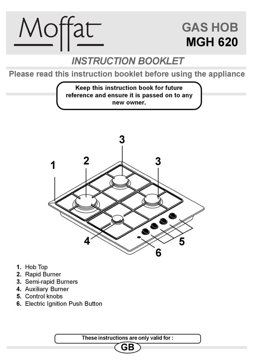
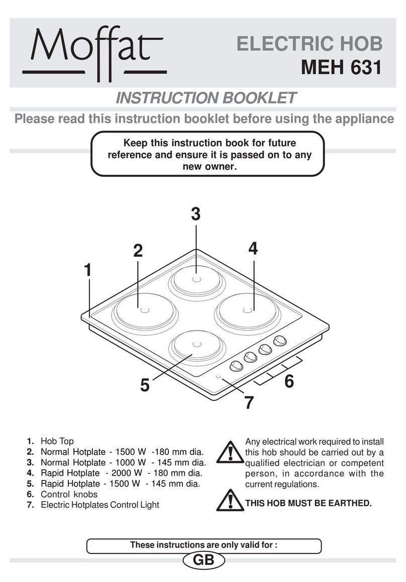
1. HobTop
2. Rapid Burner
3. Semi-rapid Burners
4. Auxiliary Burner
5. Control knobs
6. Electric Ignition Push Button
1
3
2
4
3
65
These instructions are only valid for :
GB

2
Important Safety Information
You MUST read hese warnings carefully before installing or using the
hob. If you need assistance, contact our Customer Care Department on
08705 950950
Installation
Thisappliancemustbeinstalledand
serviced by a competent person as
stated in the Gas Safety (Installation
andUse)RegulationsCurrentEditions
and the IEE Wiring Regulations.
Removeallpackagingbeforeusingthe
hob.
Ensure that the gas and electrical
supply complies with the type stated
on the rating plate, located near the
gas supply pipe.
Do not attempt to modify the hob in
any way.
Child Safety
This hob is designed to be operated
byadults.Donotallowchildrentoplay
nearorwiththehob.
Thisapplianceis notintendedfor use
by children or other persons whose
physical, sensory or mental
capabilitiesorlack of experienceand
knowledgepreventsthem fromusing
the appliance safely without
supervision or instruction by a
responsiblepersontoensurethatthey
can use the appliance safely.
The hob gets hot when it is in use.
Children should be kept away until it
hascooled.
Childrencanalsoinjurethemselvesby
pulling pans or pots off the hob.
During Use
This hob is intended for domestic
cooking only. It is not designed for
commercialorindustrial purposes.
This appliance is not connected to a
combustion products evacuation
device. It must be installed and
connectedin accordancewith current
installation regulations. Particular
attentionshallbegivento therelevant
requirementsregardingventilation.
Whenin useagas cookingappliance
will produce heat and moisture in the
room in which it has been installed.
Ensure there is a continuous air
supply, keeping air vents in good
condition or installing a cooker hood
witha venting hose.
When using the hob for a long period
time, the ventilation should be
improved, by opening a window or
increasingtheextractor speed.
Do not use this hob if it is in contact
withwater. Do not operate the
hobwithwet hands.
Ensure the control knobs are in the
‘OFF’ position when not in use.
When using other electrical
appliances,ensurethecabledoesnot
come into contact with the hot
surfacesofthe cooking appliance.
Unstable or misshapen pans should
not be used on the hob as unstable
panscancauseanaccidentbytipping
orspillage.
Neverleavethehobunattendedwhen
cooking with oil and fats.

3
The following symbols will be found in the
text to guide you throughout the
Instructions:
Safety Instructions
Step by step instructions for an
operation
Hints and Tips
Environmental information
GuidetoUsetheinstructions
Never use plastic or aluminium foil
dishes on the hob.
Perishable food, plastic items and
areosolsmay beaffectedbyheatand
should not be stored above or below
the hob unit.
Service
This hob should only be repaired or
serviced by an authorised Service
Engineerandonly genuine approved
sparepartsshouldbeused.
Environmental
Information
Afterinstallation,pleasedisposeofthe
packaging with due regard to safety
andtheenvironment.
When disposing of an old appliance,
make it unusable, by cutting off the
cable.
Thesymbol on the productoron
itspackagingindicatesthatthisproduct
may not be treated as household
waste.Insteaditshallbehandedover
to the applicable collection point for
the recycling of electrical and
electronicequipment.Byensuringthis
product is disposed of correctly, you
will help prevent potential negative
consequencesfortheenvironmentand
humanhealth,which couldotherwise
be caused by inappropriate waste
handlingofthis product.
For more detailed information about
recycling of this product, please
contact your local city office, your
household waste disposal service or
the shop where you purchased the
product.
Thisappliancecomplies with
thefollowing E.E.C.
Directives:
* 73/23 - 90/683
(LowVoltageDirective);
* 93/68 (GeneralDirectives);
* 89/336 (Electromagnetical
CompatibilityDirective);
* 90/396 (GasAppliances),
andsubsequent modifications
Keep this instruction book for
future reference and ensure it is
passed on to any new owner.

4
Maintenance
and Cleaning
Before any maintenance or cleaning
can be carried out, you must
DISCONNECT the hob from the
electricitysupply.
Thehobisbestcleanedwhilstitisstill
warm, as spillage can be removed
moreeasilythan if it is leftto cool.
The Hob Top
Regularly wipe over the hob top using a soft
clothwellwrung out in warmwatertowhicha
littlewashingupliquidhasbeenadded.Avoid
the use of the following:
-householddetergent andbleaches;
- impregnated pads unsuitable for non-stick
saucepans;
-steelwool pads;
-bath/sinkstainremovers.
Shouldthehobtopbecomeheavilysoiled,itis
recommended that a cleaning product such
as Hob Brite or Bar Keepers Friend is used.
Pan Supports
The pan supports are dishwasher proof. If
washingthembyhand,takecarewhendrying
themastheenamellingprocessoccasionally
leaves rough edges. If necessay, remove
stubbornstainsusingapastecleaner.
Ignition candle
The electric ignition is obtained through a
ceramic"candle"and a metal electrode (fig. 1,
letter C). Keep these components well clean,
to avoid difficult lighting, and check that the
burner crown holes are not obstructed.
The Burners
Theburnercapsandcrownscanberemoved
forcleaning.Washtheburnercapsandcrowns
usinghotsoapywater,andremovemarkswith
a mild paste cleaner. A well moistened soap
impregnatedsteelwoolpadcanbeusedwith
caution,ifthemarksareparticularlydifficultto
remove. After cleaning, be sure to wipe dry
with a soft cloth.
Operation
HobBurners
To light a burner:
pushtheelectricignitionpushbuttonwhich
ismarkedbya little spark ( );
at the same time turn the relevant control
knobanticlockwisetomaximumposition;
thenadjusttheflameasrequired.
If the burner does not ignite, turn the control
knob to zero, and try again.
To ensure maximum burner efficiency, you
should only use pots and pans with a flat
bottomfittingthesizeoftheburnerused(see
table).
Burner minimum maximum
diameter diameter
Rapid 180 mm. 260 mm.
Semi-rapid 120 mm. 220 mm.
Auxiliary 80 mm. 160 mm.
As soon as a liquid starts boiling, turn
down the flame so that it will barely
keeptheliquidsimmering.
Ifthecontrolknobsbecomedifficultto
turn,pleasecontactyourlocal Service
ForceCentre.
Ifyou useasaucepanwhichis smaller
thanthe recommendedsize,the flame
will spread beyond the bottom of the
vessel,causingthehandletooverheat.
Take care when frying food in hot
oil or fat, as the overheated
splashes could easily ignite.

5
SYMPTOM
There is no spark when lighting the
gas.
The gas ring burns unevenly.
SOLUTION
Check that the unit is plugged in and the
electrical supply is switched on.
Check that the RCCB has not tripped (if
fitted).
Check the mains fuse has not blown.
Check the burner cap and crown have
beenplacedcorrectly,e.g.aftercleaning.
Check the main jet is not blocked and the
burner crown is clear of food particles.
Check the burner cap and crown have
beenplacedcorrectly,e.g.aftercleaning.
Something not working
Ifthe appliance isnotworking correctly, pleasecarryoutthefollowingchecks,beforecontacting
yourlocalServiceForceCentre.
IMPORTANT:
If you call out an engineer to a fault listed below, or to repair a fault caused by
incorrectuseorinstallation,a charge will be made even if the appliance is underguarantee.

6
Overalldimensions Cut out dimensions
Width: 580 mm. Width: 550 mm.
Depth: 500 mm. Depth: 470 mm.
Engineers technical data
Instructions
for the Installer
Rear Left Burner (semi-rapid)
Heat Input 2.0 kW (6824 BTU/HR)
Front Left Burner (rapid)
Heat Input 3.0 kW (10236 BTU/HR)
2.8 kW L.P.G. (9554 BTU/HR)
Rear Right Burner (semi-rapid)
Heat Input 2.0 kW (6824 BTU/HR)
Front Right Burner (auxiliary)
Heat Input 1.0 kW (3412 BTU/HR)
Supply connections
Gas: RC 1/2 inch (1/2 inch male) Rear right
hand corner
Electric: 230V~50Hz supply, 3 coreflexible
cable with non rewireable plug fitted with a
3 amp cartridge fuse.
Burner Dia. Tap By-pass
1/100 mm
Auxiliary 28
Semi-rapid 32
Rapid 40
Aerationadjustmentnone
APPLIANCE CLASS: 3
APPLIANCE CATEGORY: II 2H3+
APPLIANCE GAS SUPPLY:
Natural gas G20 (2H) / 20mbar
Illi
Thishobmustbeinstalledbyqualified
personnel to the relevant British
Standards.
Anygasinstallationmustbecarriedout
byaregistered CORGI installer.
The manufacturer will not accept
liability, should the above instructions
or any of the other safety instructions
incorporated in this book be ignored.

7
Important safety requirements
700 mm
400 mm
100 mm
400 mm
50 mm
55 mm
50 mm
650 mm
400 mm
400 mm
100 mm
50 mm
50 mm
55 mm
600 mm
FO 0812
FO 0813
FITTINGTHE GASHOB
WITHOUT A COOKER HOOD ABOVE
FITTINGTHE GASHOB
WITH A COOKER HOOD ABOVE
Thishobmustbe installedin accordance with
the Gas Safety (Installation and Use)
Regulations (Current Edition) and the IEE
Wiring Regulations (Current Edition).
Provision for ventilation
Detailed recommendations are contained
in the following British Standards Codes Of
Practice:B.S.6172/B.S.5440,Part2andB.S.
6891CurrentEditions.
Thehob shouldnotbe installedinabed sitting
room with a volume of less than 20 m3. If it is
installedinaroom ofvolumeless than5m3an
airventofeffectiveareaof110cm2isrequired.
Ifitisinstalledinaroomofvolumebetween5
m3and 10 m3an air vent of effective area of
50cm2isrequired,whileifthevolumeexceeds
11 m3no air vent is required.
However,iftheroomhasa door which opens
directly to the outside no air vent is required
evenifthevolumeis between 5 m3and11 m3.
If there are other fuel burning appliances in
the same room, B.S. 5440 Part 2 Current
Edition,shouldbeconsultedtodeterminethe
requisiteairvent requirements.
Location
The hob may be located in a kitchen, a
kitchen/diner or bed sitting room, but not in
a bathroom, shower room or garage.Before
making the cut out in the worktop ensure
that the edges of the hob that are to be near
either a side or rear wall have a minimum
distance of 55 mm. between the edge of the
hob and the wall.
The minimum distance combustible
material can be fitted above the hob is 400
mm. If it is fitted below 400 mm. a space of
50 mm. must be allowed from the edges of
the hob.
The minimum distance combustible material
canbe fitteddirectlyabovethehob is700mm.
A minimum distance of 100 mm. must be
left between the side edges of the hob and
any adjacent cabinets or walls.

8
When the hob is first installed
Once the hob has been installed, it is
important to remove any protective
materials, which were put on in the
factory.
On the end of the shaft, which includes the
GJ 1/2" threaded elbow, adjustment is fixed
so that the washer is fitted between the
componentsasshowninthediagram.Screw
the parts together without using excessive
force. A) End of shaft with nut
B) Washer
C) Elbow
It is important to install the elbow
correctly,withtheshoulderonthe end
of the thread, fitted to the hob
connectingpipe.
Failureto ensurethecorrectassembly
willcauseleakageofgas.
FO 0814
Gas Connection
Connection to the gas supply should be with
either rigid or semi-rigid pipe, i.e. steel or
copper.
The connection should be suitable for
connecting to RC 1/2 (1/2 BSP male thread).
When the final connection has been made, it
isessentialthat a thoroughleaktestiscarried
out on the hob and installation.
Ensure that the main connection pipe does
not exert any strain on the hob.
FO 0264
Cut Out Size
Thedimensionsof thecut-outaregivenin the
diagram.
550
470
30
FO 2098
Dimensionsaregiveninmm.
Installation

9
FO 0763 FO 0764
Dimensions are
given in mm.
Building In
Building over a cupboard or
drawer
If the hob is to be installed above a cupboard
or drawer it will be necessary to fit a heat
resistant board below the base of the hob on
the underside of the work surface.
It is also recommended to carry out the
electrical connection to the hob as shown in
diagrams 1 and 2.
Building over a kitchen unit
with door
Proper arrangements must be taken in
designingthefurnitureunit,inordertoavoidany
contact with the bottom of the hob which can
be heated when it is operated. The
recommendedsolution isshownindiagram3.
The panel fitted under the hob ("a") should
be easily removable to allow easy access if
technical assistance is needed. The space
behind the kitchen unit ("b") can be used for
connections.
FO 1013
3
FO 0199
Fitting the Hob into the
worktop
Carry out the building in of the hob as
follows:1. putthesealssuppliedwiththehob,
on the edges of the cut out, taking
care that the seals meet without
overlapping;
2. placethehobinthecut out, taking
carethatitis centred;
3. fix the hob with the relevant fixing
clamps and screws, as shown in
the diagram. When the screws
have been tightened, the excess
sealcanberemoved.
Theedgeofthehobformsadoublesealwhich
preventstheingressofliquids.
Sealing
gasket
ON/OFF SWITCH
FLEX
OUTLET
ON/OFF SWITCH
FLEX
OUTLET
12

10
Permanent Connection
In the case of a permanent connection, it is
necessarythatyouinstalladoublepoleswitch
between the hob and the electricity supply
(mains), with a minimum gap of 3 mm.
between the switch contacts and of a type
suitable for the required load in compliance
withthecurrentelectricregulations.
The switch must not break the yellow and
greenearthcable at any point.
Ensure that the hob supply cable
does not come into contact with
surfaces with temperatures higher
than 50 deg. C.
Electrical connections
Any electrical work required to install
this hob should be carried out by a
qualified electrician or competent
person,in accordancewiththecurrent
regulations.
THISHOBMUSTBEEARTHED.
The manufacturer declines any liability
should these safety measures not be
observed.
This hob is designed to be connected to a
230 V
~
50 Hz AC electrical supply.
Before switching on, make sure the
electricity supply voltage is the same as that
indicated on the hob rating plate. The rating
plate is located on the bottom of the hob. A
copy is attached on the back cover of this
book.
The hob is supplied with a 3 core flexible
supply cable.
The wires in the mains lead are coloured in
accordancewith the following code:
GreenandYellow - Earth
Blue - Neutral
Brown -Live
1. Connect the green and yellow (earth)
wire to the terminal which is marked with
the letter 'E' or the earth symbol or
colouredgreenand yellow.The earthwire
should be about 2 cm longer than the
neutralandlivewires.
2. Connect the blue (neutral) wire to the
terminalwhichis marked withtheletter'N'
or coloured black.
3. Connect the brown (live) wire to the
terminalwhichismarkedwiththeletter'L'
or coloured red.
Uponcompletiontheremustbenocut,orstray
strands of wire present and the cable clamp
must be secure over the outer sheath.
Min. size
Cable/flex Cable / flex type Fuse
0.75 mm2H05 V2V2-F (T90) 3 A
Supply cable replacement
The cable used to connect the hob to the
electrical supply must comply to the
specificationsgivenbelow.

11
Wiring Diagram
Commissioning
Whenthehob hasbeenfullyinstalleditwill be
necessarytochecktheminimumflamesetting.
To do this, follow the procedure below.
1. Turn the gas tap to the MAX position and
ignite.
2. Set the gas tap to the MIN flame position
then turn the control knob from MIN to
MAXseveraltimes.Iftheflameisunstable
or is extinguished follow the procedure
below.
Procedure:
1. Re-ignite the burner and set to MIN.
2. Remove the control knob.
3. To adjust, use a thin bladed screwdriver
and turn the adjustment screw (it may be
located inside the gas tap shaft or on the
body of the gas tap itself, according to
differentmodels-seediagram).Adjustthe
minimum gas flow level until the flame is
steadyanddoesnotextinguish, when the
knob is turned from MIN to MAX. Repeat
thisprocedureforall burners.
Minimum adjustment screw
A. IGNITOR SWITCH
B. IGNITOR UNIT

12
Conversion from Natural Gas to LPG
It is important to note that this model is
designed for use with natural gas but can be
convertedforusewithbutane or propanegas
providing the correct injectors are fitted. The
gasrate is adjusted to suit.
Method
1. Ensure that the gas taps are in the 'OFF'
position
2. Isolatethehobfromtheelectricalsupply
3. Remove all pan supports, burner caps,
rings, crowns and control knobs.
4. With the aid of a 7mm box spanner the
burner injectors can then be unscrewed
and replaced by the appropriate LPG
injectors (see "Characteristics of gas
burners" on the next page).
To adjust the gas rate
With the aid of a thin bladed screwdriver
completely tighten down the by pass
adjustment screw. Upon completion affix the
replacementrating plate on theunderside of
the hob.
IMPORTANT
Thereplacement/conversionofthegas
hob should only be undertaken by a
competentperson.
Pressure Testing
Remove the pan supports and
the burner caps and crowns.
The pressure testing must be
carried out on the burners.
Proceed as follows:
1. Fit manometer tube over the
injector.
2. Turn on the burner gas supply
and ignite another burner.
3. The pressure reading should be
nominally 20 mbar and must be
between 17 mbar and 25 mbar.
4. Turn off the burner supplies.

13
BURNER RAPID SEMI-RAPID AUXILIARY
(large) (medium) (small)
POSITION MAX MIN MAX MIN MAX MIN
NOMINALTHERMAL 3.0 0.65 2.0 0.45 1.0 0.33
POWER (kW)
NOMINAL FLOW 0.286 0.062 0.190 0.043 0.095 0.031
RATE (m3/h)
NOZZLEREFERENCE 119 Adjust. 96 Adjust. 70 Adjust.
(1/100mm)
NOMINALTHERMAL 2.8 0.65 2.0 0.45 1.0 0.33
POWER (kW)
NOMINAL FLOW 202 47 144 32 72 24
RATE (g/h)
NOZZLEREFERENCE 86 40 71 32 50 28
(1/100mm)
NATURAL
GAS
20mbar
TYPE OF
GAS Characteristics
LPGGAS
28-30/37
mbar
VALUE = 49.92 MJ/Kg VALUE = 37.78 MJ/m
3
Ws - 50.7 MJ/ m
3
Characteristics of gas burners

ServiceandSpareParts
If you require spare parts or an engineer
contact your local Service Force Centre by
telephoning:
08705 929 929
Yourcallwillbe routed to the Service Centre
covering your post code area. The
addresses of Service Force Centres are
detailed on the following pages.
CUSTOMERCARE
ForgeneralenquiriesconcerningyourMoffat
appliance and for further information on
Moffatproducts,contactourCustomerCare
Departmentbyletterortelephoneasfollows:
Customer Care Department
Moffat
55-77 High Street
Slough
Berkshire SL1 1DZ
Tel : 08705 950950
* calls to this number may be recorded for training
purposes
GuaranteeConditions
Home visits are made between 8.30am and
5.30pm Monday to Friday.Visits may be
available outside these hours, in which case
a premium will be charged.
Exclusions
Thisguarantee does notcover:
*Damage or calls resulting from
transportation, improper use or neglect, the
replacement of any light bulbs or removable
parts of glass or plastic.
*Costs incurred for calls to put right an
appliance which is improperly installed or
calls to appliance outside the United
Kingdom.
*Appliances found to be in use within a
commercial or similar environment, plus
those which are the subject to rental
agreements.
* Products of Moffat manufacture which are
not marketed by Moffat.
EuropeanGuarantee
This appliance is guaranteed by Electrolux in each of the countries listed below for the period
specified in the appliance guarantee or otherwise by law. If you move from one of these countries
to another of the countries listed below the appliance guarantee will move with you subject to the
following qualifications:
· The appliance guarantee starts from the date you first purchased the appliance which will
be evidenced by production of a valid purchase document issued by the seller of the
appliance.
· The appliance guarantee is for the same period and to the same extent for labour and parts
as exists in your new country of residence for this particular model or range of appliances.
· The appliance guarantee is personal to the original purchaser of the appliance and cannot
be transferred to another user.
· The appliance is installed and used in accordance with instructions issued by Electrolux
and is only used within the home, i.e. is not used for commercial purposes.
· The appliance is installed in accordance with all relevant regulations in force within your
new country of residence.
TheprovisionsofthisEuropeanGuaranteedonotaffectanyoftherightsgrantedtoyoubylaw.


Grafiche MDM - Forlì
35676-2903 07/06
www.electrolux.com
This manual suits for next models
3
Table of contents
Other Moffat Hob manuals

Moffat
Moffat MGH 620 User manual

Moffat
Moffat MGH 620 User manual

Moffat
Moffat MGH700X User manual

Moffat
Moffat MG35W User manual

Moffat
Moffat MEH 630W User manual

Moffat
Moffat ME45B User manual

Moffat
Moffat MG35B User guide

Moffat
Moffat MCP651 User manual

Moffat
Moffat MGH620W User manual

Moffat
Moffat MGH620B User manual
Popular Hob manuals by other brands

Samsung
Samsung NZ64R3525CK User & installation manual

Kuppersbusch
Kuppersbusch GWS 307 Instructions for use and installation instructions

Zanussi
Zanussi ZGG75524 user manual

KORTING
KORTING HG 695 CTN instruction manual

Barazza
Barazza 1PTA90 Installation and use manual

Kingfisher
Kingfisher CL5ZFXLK90 manual