MOKO LW004 Datasheet -CT User manual

Datasheet
LW004-CT
MOKO TECHNOLOGY LTD.
Version 2.1 www.mokosmart.com
User Manual

CONTENT
1 About this Manual .................................................................................. 3
2 Product Introduction .............................................................................. 3
2.1Overview.................................................................................................................................3
2.2Application..............................................................................................................................3
2.3Product Specifications............................................................................................................3
2.3.1 Appearance.................................................................................................................3
2.3.2 Mechanical Size...........................................................................................................3
2.3.3 LED Indicators and Button ..........................................................................................4
3 Device Feature and Function .................................................................. 6
3.1 Introduction to Device Application........................................................................................6
3.1.1 Contact Tracing ...........................................................................................................6
3.1.2 Social Distance Alarm..................................................................................................7
3.1.3 Gather Warning...........................................................................................................8
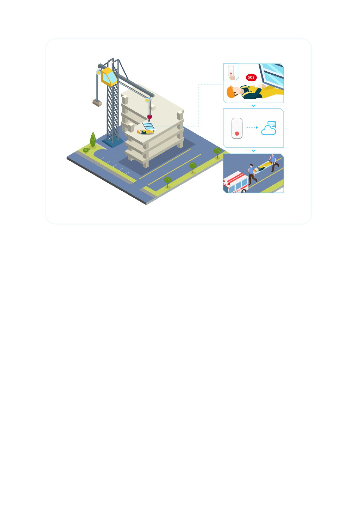
3.1.4 SOS Alarm....................................................................................................................9
3.2 Bluetooth Capabilities..........................................................................................................10
3.2.1 Bluetooth Advertise ..................................................................................................10
3.2.2 Bluetooth Scan..........................................................................................................12
3.3 LoRaWAN Capabilities..........................................................................................................14
3.4 3-Axis Accelerometer Capabilities .......................................................................................15
3.4 Device Status Indication.......................................................................................................15
3.5 Device Information Upload..................................................................................................15
3.6 Battery Performance............................................................................................................15
3.7 Time Synchronization...........................................................................................................15
3.8 Configuration Tool ...............................................................................................................16
4 Uplink Payload ...................................................................................... 16
4.1 Device Information Payload.................................................................................................16
4.2 Contact Tracing Payload.......................................................................................................17
4.3 Distance Alarm Payload .......................................................................................................18
4.4 SOS Alarm Payload...............................................................................................................20
4.5 3-Axis Payload ......................................................................................................................22
5 Maintenance instruction....................................................................... 23
6 Revision History .................................................................................... 24

LW004-CT
3www.mokosmart.com
1 About this Manual
The purpose of this manual is to outline how to apply LW004-CT in suitable scenarios, as well as
the main function of LW004-CT.
2 Product Introduction
2.1 Overview
The LW004-CT is a long-range contact tracker for Class A type devices based on the
LoRaWAN open protocol and is compatible with the LoRaWAN protocol. It is small, compact, and
easy to use. It can be used to track close contact and social safety distance reminder.
2.2Application
➢Positioning & Location Tracking
➢Contact Tracing
➢Safe Distance Reminder
2.3Product Specifications
2.3.1 Appearance
2.3.2 Mechanical Size

LW004-CT
4www.mokosmart.com
2.3.3 LED Indicators and Button
Items
Indicator
Operation
Remarks
Turn ON
Green LED Blink 3S
Press and hold the power
button for 3 seconds till the
green indicator flashes
quickly and release. The
indicator will flash green for
3 seconds to show the
LW004-CT is turned on.
Turn OFF
Solid red and keep 3S
Press and hold the power
button for 3 seconds till the
LED indicate red and
release. The LED will
indicate red for 3 seconds to
show the LW004-CT is
turned off.
Hardware
reset
Solid green and keep
3S, then device restart
and green LED Blink 3S
When the device is off,
press and hold the power
button for 10 seconds till
the LED indicate solid green
3s and release button.
If user press and hold the
power button over 12
seconds, the device will
turn off after hardware
reset.
After it reset successfully
the device parameters will
be reset to factory values
except the MAC address.
Bluetooth
Green LED Blink 1S
Connect to the device via
When the device in alarm

LW004-CT
5www.mokosmart.com
connection
established
successfully
APP successfully
status the indicator may be
not visible.
Bluetooth
connection
disconnected
Red LED Blink 1S
APP disconnect to the
device
When the device in alarm
status the indicator may be
not visible.
Join LoRa
Network
Solid white and keep 3S
If the device had never
Joined any network, after
turning on, the device will
automatically send join
request
It will send join request
automatic after power on
the device or save “LoRa
Setting” parameter
in APP.
When the device in alarm
status the indicator may be
not visible.
Trigger
Distance
Alarm
Red LED Blink 3S and
motor vibrate for one
cycle. If the alarm
continues, the motor
will continue to vibrate
for another one cycle
and the red light will
blink for another 3
seconds.
No matter whether the
LoRa network connection is
successful, the alarm will be
alerted when the safety
distance reminder condition
is reached.
Motor alarm and indicator
light alarm can be
configured with switch
status. The default mode
of motor alarm and
indicator light alarm is on.
Turn off the
indicator light
and motor
vibration for
alarm
Blue LED Blink 3S
Press function button and
hold on 5S
Firmware
Upgrade
Green LED Blink during
the upgrade/Solid
Green and keep 2S after
upgrade successfully
/Solid Red and keep 2S
after upgrade failed
Firmware upgrade via OTA
in DFU mode
Charging
Blue LED blink during
Charging
Plug in type-c charger
Full Charged
Solid Green
Plug in type-c charger
The lights go out after
unplug the charger
Low Battery
Reminder
Yellow LED Blink once
every 10s
Battery level lower than the
set value
Status
indicators
Solid Green and keep
one second means that
the device is on,
otherwise the device is
off.
Double click the power
button
Trigger SOS
Alarm
Solid Red and keep one
second, then Solid
Green and keep one
Double click the function
button in 1s

LW004-CT
6www.mokosmart.com
second, then Solid Blue
and keep one second.
3 Device Feature and Function
3.1 Introduction to Device Application
3.1.1 Contact Tracing
LW004-CT is commonly used for contact tracing in schools, hospitals, companies, factories and
other densely populated areas. The close contact information can be used for surveillance and
early warning When a major public health event occurs.
When the device is powered on and normally connected to the network, the device will report
Contact Tracing Payload at fixed intervals (Interval time can be set).
Note: Users can choose whether to include location information in the Contact Tracing Payload. If
location information is included, users need to install the location beacon in advance.
Example of corporate office scenario:
➢All employees should wear the LW004-CT, and install the fixed location beacon (Take Moko
beacon product H2 as an example) on the corresponding location in the office area to ensure
that the Bluetooth broadcast range of these Bluetooth Beacons can cover the whole office.
➢By setting the broadcast information of LW004-CT & H2 and the filter condition of LW004-CT,
you can successfully ignore the unneeded Bluetooth device data, and you can set the
determination distance of close contact. (Refer to Chapter 7 for an example of how to set the
filter condition)
➢In case of close Contact between employees wearing LW004-CT, each employee's LW004-CT
will record this close contact. Contact Tracing Payload will be reported in turn after reaching
the reporting time point.
➢Since each LW004-CT has a unique MAC address and the installation location of H2 is known
in advance, by analyzing the Contact Tracing Payload, the user can obtain the information
about the person in close contact, when the close contact occurred and the approximate
location where the close contact occurred.

LW004-CT
7www.mokosmart.com
3.1.2 Social Distance Alarm
Distance alarm function is mainly used for distance keeping in public places. Users can set
different distance requirements according to different scenes, which can be achieved by setting
Alarm Trigger RSSI.
Example of hospital:
➢All employees should wear the LW004-CT.
➢By setting the broadcast information of LW004-CT and the Filter Condition of LW004-CT,
Unneeded Bluetooth device data can be successfully ignored. (Refer to Chapter 7 for an
example of how to set a filter condition)
➢Users can adjust the determination distance of social distance alarm by setting Gather
Warning RSSI.
➢The system will judge all close contacts, if the distance of the close contact is less than the set
value, the device will trigger a distance alarm, at which time the device will vibrate, the
indicator light will flash red, and the Distance Alarm Payload will be reported immediately.
Distance Alarm Payload mainly contains close contact data for close contacts that trigger
distance alarms.
➢When the distance alarm is triggered, the corresponding employee should pay attention to his
or her position with others in time and keep a certain distance.
Note: Users can choose whether to include location information in the Close Contact Data. If
location information is included, users need to install the location beacon in advance.

LW004-CT
8www.mokosmart.com
3.1.3 Gather Warning
Gather Warning is mainly used in public social occasions, such as hospitals, schools, nursing homes,
factories and other scenarios.
When a certain number of people gather near a certain person, the LW004-CT worn by this person
will sound an alarm, the device will vibrate and the indicator light will flash yellow.
Users can adjust the Gather Warning RSSI according to different scenarios, that is, to adjust the
coverage space of the Gather Warning. The coverage space is a circle with a certain person as the
center, and the radius of the circle is determined by Gather Warning RSSI.
Note: According to the usage logic, the priority of Social Distance Alarm is higher than Gather
Warning, so the coverage of Gather Warning will be larger than Social Distance alarm. When a
Social Distance Alarm and a Gather Warning occur simultaneously, only Social Distance Alarm will
take effect.

LW004-CT
9www.mokosmart.com
3.1.4 SOS Alarm
SOS alarm is mainly used for emergency situations, suitable for nursing homes, schools, hospitals,
etc.
➢When the user wearing LW004-CT encounters an emergency, the SOS alarm can be triggered
once by double-clicking the red button on the front of the device within 1S, the corresponding
indicator light will flash.
➢Each time the SOS alarm is triggered, the device will upload two SOS Alarm Payload. The first
one will be uploaded immediately after the SOS alarm is triggered, and the other one will be
reported N minutes later. If the user triggers the SOS alarm again before the second SOS
Alarm Payload is sent out, another SOS Alarm Payload will be uploaded N minutes after the
second SOS Alarm Payload is sent out.
➢Since close contact tracking is always ongoing, when a user triggers an SOS alarm, the SOS
Alarm Payload will include information about the wearer's last close contact before the alarm
and the location information at current time.
Note: Users can choose whether to include location information in the SOS Alarm Payload.

LW004-CT
10 www.mokosmart.com
3.2 Bluetooth Capabilities
3.2.1 Bluetooth Advertise
When user turn on the LW004-CT, the LW004-CT will constantly Bluetooth broadcast unless the
device is set to the unconnected state.
When the device is unconnected, the device will only broadcast for one minute after each reboot.
The user can scan the LW004-CT and establish a link with the LW004-CT through the Bluetooth
function of the cell phones, iPad, etc. After the Bluetooth connection is established, the user can
use the MKLoRa APP to set the parameters and upgrade the firmware of the LW004-CT.
Note: About the MKLoRa app, pls refer to LW004-CT APP Guide.
The broadcast content of LW004-CT is divided into broadcast packet and response packet. The
following is an example of the broadcast content:

LW004-CT
11 www.mokosmart.com
3.2.1.1 Broadcast Packet
LEN
TYPE
VALUE
2
0x01
0x06
26
0xFF
0x4C 00 02 15 E2 C5 6D B5 DF FB 48 D2 B0 60 D0 F5 A7 10
96 E0 00 00 00 00 BF
⚫UUID: E2C56DB5-DFFB-48D2-B060-D0F5A71096E0
⚫Major:0 (0x00 00)
⚫Minor:0 (0x00 00)
⚫RSSI@1m: -65dBm (0xBF)
3.2.1.2 Response Packet
LEN
TYPE
VALUE
18
0x16
0x01 AA 01 00 00 00 00 BF 00 0E 64 D3 64 40 05 4A 1C
9
0x09
0x4C 57 30 30 34 2D 43 54
⚫Service UUID: 0x AA 01
⚫Device Type: LW004-CT (0x01)
⚫Major: 0 (0x00 00)
⚫Minor: 0 (0x00 00)
⚫RSSI@1m: -65dBm (0xBF)
⚫Tx Power: 0 dBm (0x00)
⚫Device Status: 0x0E (0x0E = 0b0000 1110)
➢Bit3(1 means connectable state; 0 means not connectable state)
➢Bit2(1 means Scan open; 0 means Scan close)
➢Bit1(1means with 3-axis; 0 means without 3-axis)
➢Bit0(1 means with; 0 means without Flash)

LW004-CT
12 www.mokosmart.com
⚫Battery Level: 100% (0x64)
⚫MAC Address: D3 64 40 05 4A 1C (0xD3 64 40 05 4A 1C)
⚫Device ADV Name:LW004-CT (0x4C 57 30 30 34 2D 43 54)
3.2.2 Bluetooth Scan
When scan switch status is on, the device will start to scan beacons nearby and cache the beacon
information that meets the conditions.
Users can set the scanning intensity according to different application scenarios, a total of three
levels of high, medium and low can be set.
Note: The intensity of the Bluetooth scan affects the broadcast performance of the device. If the
broadcast performance of the device is found to be affected, it is recommended to reduce the ADV
Interval of the device, but this will increase the power consumption of the device.
The Bluetooth scanning function of LW004-CT has two main parts: Contact Tracking Scanning and
Location Beacon Scanning. They will not affect each other.
3.2.2.1 Contact Tracking Scanning
Contact Tracking Scanning is mainly used to scan the LW004-CT worn by others. By scanning the
device data of LW004-CT, the information of people in close contact with the user can be recorded.
The following is the specific description of Contact Tracking Scanning rules:
①There are two sets of filter conditions, one is Filter Condition A, and other one is Filter
Condition B. Each filter condition has a separate switch setting, which can be arbitrarily switched
on or off.
②When both of Filter Condition A and Filter Condition B are switched on, the relationship
between two sets of filter conditions can be set as AND or OR.
AND: Beacon information is stored and reported only when the data meets both Filter Condition A
and Filter Condition B.
OR: Beacon information is stored and reported when the beacon data meets either filter condition
A or filter condition B.
If only one condition is opening, the data that meets this filter condition will be saved and
uploaded.
Note: When both Condition A and Condition B are off, the Contact Tracking Scanning function can
continue to work without filtering conditions.
③There are seven filter items in each set of filter conditions, which are RSSI Filter, MAC Address

LW004-CT
13 www.mokosmart.com
Filter, UUID Filter, ADV Name Filter, Major Filter, Minor Filter and Raw Data Filter. Only if these
seven filter items are met at the same time can this filter condition be considered to be met.
Each filter item can be set to off, positive filter and reverse filter.
Off: Regardless of this filter item.
Positive filter: If the device being scanned matches the content of this filter item, it is
considered to meet the filter item.
Reverse filter: If the device being scanned does not match the contents of this filter
item, it is considered to meet the filter item.
Note: For the RSSI Filter item, it can’t be set to positive filter. Refer to LW004-CT APP Guide for
detailed Settings of filter items and an example.
3.2.2.1 Location Beacon Scanning
Location Beacon Scanning is mainly used to scan the fixed location beacon. By scanning the
broadcast content of location beacon, the approximate location of the close contact can be
recorded and analyzed.
The following is the specific description of Location Beacon Scanning rules:
①There are two sets of filter conditions, one is Filter Condition A, and other one is Filter
Condition B. Each filter condition has a separate switch setting, which can be arbitrarily switched
on or off.
②When both of Filter Condition A and Filter Condition B are switched on, the relationship
between two sets of filter conditions can be set as AND or OR.
AND: Beacon information is stored and reported only when the data meets both Filter Condition A
and Filter Condition B.
OR: Beacon information is stored and reported when the beacon data meets either filter condition
A or filter condition B.
If only one condition is opening, the data that meets this filter condition will be saved and
uploaded.
Note: When both Condition A and Condition B are off, the Location Beacon Scanning function will
stop working and stop reporting Location information.
③There are seven filter items in each set of filter conditions, which are RSSI Filter, MAC Address
Filter, UUID Filter, ADV Name Filter, Major Filter, Minor Filter and Raw Data Filter. Only if these
seven filter items are met at the same time can this filter condition be considered to be met.
Each filter item can be set to off, positive filter and reverse filter.
Off: Regardless of this filter item.
Positive filter: If the device being scanned matches the content of this filter item, it is
considered to meet the filter item.

LW004-CT
14 www.mokosmart.com
Reverse filter: If the device being scanned does not match the contents of this filter
item, it is considered to meet the filter item.
Note: For the RSSI Filter item, it can’t be set to Reverse filter. Refer to LW004-CT APP Guide for
detailed Settings of filter items and an example.
3.2.2.2 Filter Repeating Data
Since each Bluetooth device (LW004-CT and Location Beacons) may be scanned and saved more
than once in a scan cycle, we opened up the filtering of duplicate data. With this feature, for the
same data, we report only once in the same reporting cycle, and the data reported is the most
recently scanned.
Both Contact Tracking Scanning and Location Beacon Scanning have this function.
There are four types of Filter Repeating Data:
No: Don't do anything.
MAC: Beacon data with the same MAC will only be reported once in the same cycle
MAC + Data Type: Beacon data with the same MAC and the same beacon data type will only be
reported once in the same cycle. Common data types are IBEACONS, Eddystone and AltBeacon.
MAC + Raw Data: Beacon data with the same MAC address and raw data will only be reported
once in the same cycle.
Note: Some beacons have multiple slots and each slot can broadcast different types of data and
different content. Through the Filter Repeating Data, users can better get the data they want.
3.3 LoRaWAN Capabilities
The data of LW004-CT will be transmitted via LORA and LW004-CT is based on the standard
LoRaWAN protocol V1.0.3.
LW004-CT is compatible with mainstream gateways and mainstream servers (TTN, SENET, LORA
IOT, etc.) in the market.
Link Check MAC Commands: LW004-CT supports LinkCheck function. Users can use this function to
realize regular network monitoring function and confirm the network status of the device.
Device Time MAC Commands: LW004-CT supports the DeviceTime feature, which enables users to
periodically time their devices to avoid time offset. The Time Sync Interval of the MKLoRa APP is
the Device Time MAC Command interval. (Please refer to LW004-CT APP Guide)
Note: Some LoRa Server platforms did not support LinkCheck and DevicTtime function, for example
TTN server, if you want use device in these platforms, should set the corresponding Settings item to
0.

LW004-CT
15 www.mokosmart.com
3.4 3-Axis Accelerometer Capabilities
LW004-CT has built-in 3-Axis accelerometer sensor LIDSHTR.
The 3-Axis function is on by default. When the device moves, if it reaches the trigger threshold,
the device is considered to enter the movement status. In the movement status, the device will
periodically report the 3-Axis payload.
Customers can set LIDSHTR’s parameters and analyze 3-Axis payloads for additional application
development.
Note: For the parameter setting of the 3-axis function, please refer to LW004-CT APP Guide.
3.4 Device Status Indication
Because of the impact of power consumption, LW004-CT is not designed to have a dedicated
indicator to indicate that the device is on.
Therefore, we have designed the device status to be briefly indicated by button triggering.
When the device is on, double click the on/off button twice within 1s, Solid Green and keep one
second means that the device is on, otherwise the device is off.
Note: When the on/off indication is triggered, the device will temporarily increase the broadcast
interval to 100ms at the same time, so that users can connect to the device faster via Bluetooth.
3.5 Device Information Upload
The device will periodically report the Device Information Payload. The default report interval is
4H.
The Device Information Payload contains mainly battery level, SOS Alarm Function Enable Switch
Status, MAC address and ADV name.
3.6 Battery Performance
The LW004-CT is equipped with a 540 rechargeable battery.
With batteries, typical lifetime in a close tracking scenario is around two days (Scan intensity:
medium, Report Interval:3 minutes).
3.7 Time Synchronization
There are two methods to sync time through the MKLoRa APP or DeviceTime MAC Command

LW004-CT
16 www.mokosmart.com
function.
When the APP connect with the device success the phone system time will be sync to the device.
Device Time MAC Commands: LW004-CT supports the DeviceTime feature, which enables users to
periodically time their devices to avoid time offset.
3.8 Configuration Tool
The device can use MKLoRa app developed by Moko for quick OTA upgrades and parameter
settings. About the detail of MKLoRa, pls refer to LW004-CT APP Guide.
4 Uplink Payload
This section describes the payload messages supported by the LW004-CT.
There are five types of data reported through LoRa.
4.1 Device Information Payload
The LW004-CT will report the equipment information packet regularly, the default report interval
is 4 hours.
Byte Index
Type
Data
Type
Value
Description
Byte0
Payload Type
Uint
0x02
02 means Device Information
Payload.
01: Alarm data
Byte1
Battery Level
Uint
0x00-0x64
Convert to decimal, unit is %.
Byte 2
Alarm Enable
Setting
Uint
0x00 –0x01
00 means disable; 01 means
enable.
Byte 3 - 8
The host MAC
Uint
0X000000000000-
0XFFFFFFFFFFFF
The byte order is Big-Endian.
Example: B1 FA 1E 36 EF 03,
the real MAC address is B1 FA
1E 36 EF 03. The host refers to
the LW004-CT that reports the
data.
Byte 9 - 10
The hardware
version of
LW004-CT
Uint
0X0000 - 0XFFFF
Example: If it is 0x21 0A, the
hardware version is V2.1.10.
Byte 11- 20
ADV Name of
LW004-CT
Uint
0X0000000000000
0000000 -
0XFFFFFFFFFFFFFF
FFFFFFFF
Convert to ASCII.

LW004-CT
17 www.mokosmart.com
4.2 Contact Tracing Payload
➢Users can choose to report content according to application scenarios.
➢The smaller the number of bytes per payload, the shorter the transmission time and the lower
the power consumption
➢The optional reported contents are as follows:
①Battery Level
② The host MAC
③ The MAC and RSSI of Location Beacons
④The Raw data of the slave device
Byte Index
Type
Data Type
Value
Description
Byte0
Payload Type
Uint
0x00
00 means Contact
Tracking Payload
01: Alarm data
Byte1
Battery Level
Uint
0x00-0x64
Convert to decimal, unit
is %.
Byte 2 – 8
Timestamp
Uint
0X00000000000000
-OxFFFFFFFFFFFFFF
Convert to decimal. Byte
2-3 represents the year;
Byte 4 represents the
month; Byte 5
represents the date;
Byte 6 represents the
hour; Byte 7 represents
minute; Byte 8
represents second;
Byte 9 - 14
The host MAC
Uint
0X000000000000-
0XFFFFFFFFFFFF
The byte order is Big-
Endian. Example: B1 FA
1E 36 EF 03, the real
MAC address is B1 FA 1E
36 EF 03. The host refers
to the LW004-CT that
reports the data.
Byte 15 - 20
MAC address of
the slave device
Uint
0X000000000000-
0XFFFFFFFFFFFF
The byte order is Big-
Endian. Example: B1 FA
1E 36 EF 03, the real
MAC address is B1 FA 1E
36 EF 03. The slave
refers to the device in
emergency contact with
the host.
Byte 21
RSSI of the slave
device
Int
0X00-0XFF
Converts directly to
decimal numbers, then
Minus 256. The unit is
dBm.

LW004-CT
18 www.mokosmart.com
Byte 22 - XX
Raw data of the
slave device
Uint
The slave refers to the
device in close contact
with the host.
Byte XX-
(XX+5)
MAC address of
1st Location
Beacon
Uint
0X000000000000-
0XFFFFFFFFFFFF
The byte order is Big-
Endian. Example: B1 FA
1E 36 EF 03, the real
MAC address is B1 FA 1E
36 EF 03.
Byte (XX+6)
RSSI of 1st
Location Beacon
Int
0X00-0XFF
Converts directly to
decimal numbers, then
Minus 256. The unit is
dBm.
Byte (XX+7)-
(XX+12)
MAC address of
2nd Location
Beacon
Uint
0X000000000000-
0XFFFFFFFFFFFF
The byte order is Big-
Endian. Example: B1 FA
1E 36 EF 03, the real
MAC address is B1 FA 1E
36 EF 03.
Byte (XX+13)
RSSI of 2nd
Location Beacon
Int
0X00-0XFF
Converts directly to
decimal numbers, then
Minus 256. The unit is
dBm.
Byte (XX+14)
– (XX+19)
MAC address of
3rd Location
Beacon
Uint
0X000000000000-
0XFFFFFFFFFFFF
The byte order is Big-
Endian. Example: B1 FA
1E 36 EF 03, the real
MAC address is B1 FA 1E
36 EF 03.
Byte (XX+20)
RSSI of 3rd
Location Beacon
Int
0X00-0XFF
Converts directly to
decimal numbers, then
Minus 256. The unit is
dBm.
Byte (XX+21)
– (XX+26)
MAC address of
4th Location
Beacon
Uint
0X000000000000-
0XFFFFFFFFFFFF
The byte order is Big-
Endian. Example: B1 FA
1E 36 EF 03, the real
MAC address is B1 FA 1E
36 EF 03.
Byte (XX+27)
RSSI of 4th
Location Beacon
Int
0X00-0XFF
Converts directly to
decimal numbers, then
Minus 256. The unit is
dBm.
4.3 Distance Alarm Payload
➢Users can choose to report content according to application scenarios.

LW004-CT
19 www.mokosmart.com
➢The smaller the number of bytes per payload, the shorter the transmission time and the lower
the power consumption.
➢The optional reported contents are as follows:
①Battery Level
② The host MAC
③ The MAC and RSSI of Location Beacons
④The Raw data of the slave device
Byte Index
Type
Data Type
Value
Description
Byte0
Payload Type
Uint
0x01
01 means Distance
Alarm Payload
01: Alarm data
Byte1
Battery Level
Uint
0x00-0x64
Convert to decimal, unit
is %.
Byte 2 – 8
Timestamp
Uint
0X00000000000000
-OxFFFFFFFFFFFFFF
Convert to decimal. Byte
2-3 represents the year;
Byte 4 represents the
month; Byte 5
represents the date;
Byte 6 represents the
hour; Byte 7 represents
minute; Byte 8
represents second;
Byte 9 - 14
The host MAC
Uint
0X000000000000-
0XFFFFFFFFFFFF
The byte order is Big-
Endian. Example: B1 FA
1E 36 EF 03, the real
MAC address is B1 FA 1E
36 EF 03. The host refers
to the LW004-CT that
reports the data.
Byte 15 - 20
MAC address of
the slave device
Uint
0X000000000000-
0XFFFFFFFFFFFF
The byte order is Big-
Endian. Example: B1 FA
1E 36 EF 03, the real
MAC address is B1 FA 1E
36 EF 03. The slave
refers to the device in
emergency contact with
the host.
Byte 21
RSSI of the slave
device
Int
0X00-0XFF
Converts directly to
decimal numbers, then
Minus 256. The unit is
dBm.
Byte 22 - XX
Raw data of the
slave device
Uint
The slave refers to the
device in close contact
with the host.

LW004-CT
20 www.mokosmart.com
Byte XX-
(XX+5)
MAC address of
1st Location
Beacon
Uint
0X000000000000-
0XFFFFFFFFFFFF
The byte order is Big-
Endian. Example: B1 FA
1E 36 EF 03, the real
MAC address is B1 FA 1E
36 EF 03.
Byte (XX+6)
RSSI of 1st
Location Beacon
Int
0X00-0XFF
Converts directly to
decimal numbers, then
Minus 256. The unit is
dBm.
Byte (XX+7)-
(XX+12)
MAC address of
2nd Location
Beacon
Uint
0X000000000000-
0XFFFFFFFFFFFF
The byte order is Big-
Endian. Example: B1 FA
1E 36 EF 03, the real
MAC address is B1 FA 1E
36 EF 03.
Byte (XX+13)
RSSI of 2nd
Location Beacon
Int
0X00-0XFF
Converts directly to
decimal numbers, then
Minus 256. The unit is
dBm.
Byte (XX+14)
– (XX+19)
MAC address of
3rd Location
Beacon
Uint
0X000000000000-
0XFFFFFFFFFFFF
The byte order is Big-
Endian. Example: B1 FA
1E 36 EF 03, the real
MAC address is B1 FA 1E
36 EF 03.
Byte (XX+20)
RSSI of 3rd
Location Beacon
Int
0X00-0XFF
Converts directly to
decimal numbers, then
Minus 256. The unit is
dBm.
Byte (XX+21)
– (XX+26)
MAC address of
4th Location
Beacon
Uint
0X000000000000-
0XFFFFFFFFFFFF
The byte order is Big-
Endian. Example: B1 FA
1E 36 EF 03, the real
MAC address is B1 FA 1E
36 EF 03.
Byte (XX+27)
RSSI of 4th
Location Beacon
Int
0X00-0XFF
Converts directly to
decimal numbers, then
Minus 256. The unit is
dBm.
4.4 SOS Alarm Payload
➢Users can choose to report content according to application scenarios.
➢The smaller the number of bytes per payload, the shorter the transmission time and the lower
the power consumption.
➢The optional reported contents are as follows:
①Timestamp
② The host MAC
③ The MAC and RSSI of Location Beacons
Table of contents
Other MOKO Home Automation manuals