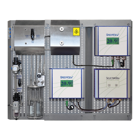
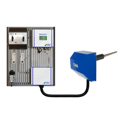
GREEN INSTRUMENTS G3621A/P User manual

PART NUMBER.: 02155
G3621A/P
STACK GAS OXYGEN ANALYZING SYSTEM
WITH DIFFUSION PROBE

Version 2.2 –Oct 2020 2

G3621a/p Stack Gas Oxygen Analyzing System
3
Content
G3621A/P STACK GAS OXYGEN ANALYZING SYSTEM WITH DIFFUSION PROBE 1
1INTRODUCTION 4
1.1 ABOUT THIS MANUAL 4
1.2 INQUIRIES AND FEEDBACK 5
1.3 ABOUT THE SYSTEM 6
2SPECIFICATIONS 7
3SAFETY ASPECTS 8
4CONTROL AT DELIVERY 9
5INSTALLATION 10
5.1 WHERE TO INSTALL THE SYSTEM 10
5.2 DIFFUSION PROBE 13
5.3 ANALYZING BOARD 15
5.3.1 Mounting Board 15
5.3.2 Air Supply Connection 15
5.3.3 Test Gas Connection 16
5.3.4 Analyzer and Electrical Connection 16
6COMMISSIONING 21
6.1 INSTALLATIONAND SETUP PRE-CHECKS 21
6.2 START OF SYSTEM 21
7ROUTINE MAINTENANCE 22
7.1 CALIBRATION 22
7.2 AIR FLOW SYSTEM 22
7.3 DIFFUSION PROBE 23
7.4 SENSOR 23
8SPARE PARTS 25
TABLE OF FIGURES
FIGURE 5-1: INSTALLATION LAYOUT OF THE G3621A WITH WELDING TYPE PROBE 11
FIGURE 5-2: INSTALLATION LAYOUT OF THE G3621P WITH THREAD TYPE PROBE 12
FIGURE 5-3: DIFFUSION PROBE STANDARD –WELDING TYPE 13
FIGURE 5-4: DIFFUSION PROBE SHORT –WELDING TYPE 14
FIGURE 5-5: DIFFUSION PROBE STANDARD –THREAD TYPE 14
FIGURE 5-6: DIFFUSION PROBE SHORT –THREAD TYPE 15
FIGURE 5-7:ANALYZING BOARD WITH G36AOXYGEN ANALYZER MOUNTED ON BOARD 17
FIGURE 5-9:ANALYZING BOARD WITH CONNECTOR BOX FOR G36P OXYGEN ANALYZER 19
FIGURE 5-10: PIPINGAND CONNECTION DIAGRAM OF THE G3621P20
FIGURE 7-1: MAINTENANCE OF THE DIFFUSION PROBE 23

Introduction
Version 2.2 –Oct 2020 4
1Introduction
1.1 About this Manual
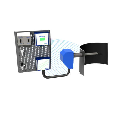
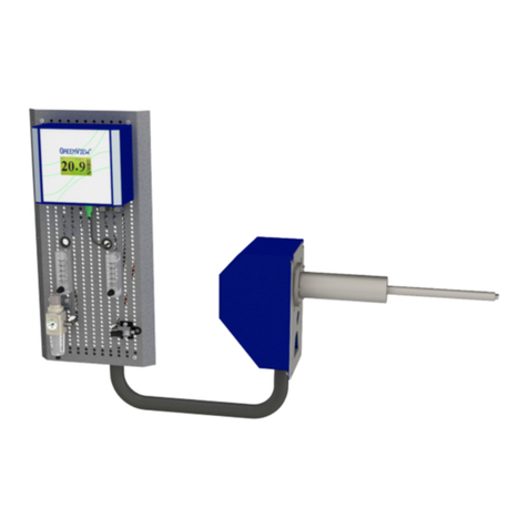
The G3621a/p Stack Gas Oxygen Analyzing System, hereafter named an SGOA System,
consists of an oxygen analyzer, an analyzing board, and a diffusion probe.
This manual contains data and instructions for the installation, operation, and mainte-
nance of the analyzing board and the SGOA System as a whole.
The instructions for installation, operation, and maintenance of the analyzers are provid-
ed in separate manuals:
The G36a Oxygen Analyzer manual (p#01245) –IP67 box
The G36p Oxygen Analyzer manual (p#01381) –panel mounted
Therefore, for the installation, operation, and maintenance of an entire SGOA System,
this manual and the concerned oxygen analyzer manual must be read carefully in their
entirety.
The instructions have been made in general terms and do not take into consideration the
existing equipment and its installation. As such, the manual is designed for the standard
G3621a/pSGOA System with Diffusion Probe.
This manual does not describe all possible situations but only the most common and
known situations and cannot replace the necessary instruction and education of the per-
sonnel.
Attention
Before operation read all instructions and warnings within this manual and associated
documentation. Improper use may cause personal injury and/or damage of equipment
and may void the warranty.
Green Instruments A/S disclaims any responsibility for damage and/or injury caused
by improper installation, use or maintenance of the equipment.
Should situations not described in this manual occur which cannot be solved in accord-
ance with normal known practice and good workmanship, the operator should contact
Green Instruments A/S for instructions.

G3621a/p Stack Gas Oxygen Analyzing System
5
This manual does not claim to cover all details or variations in the equipment or to
provide for every possible contingency that may arise during installation, operation, or
maintenance.
Green Instruments A/S reserves the right to minor alterations and improvements owing to
developments without being obliged to enter the corresponding changes in this manual.
Green Instruments A/S reserves the copyright of the manual. Without prior written per-
mission of Green Instruments A/S, the manual may not be copied and given to unauthor-
ized people.
1.2 Inquiries and Feedback
All claims and inquiries for spares shall be addressed to Green Instruments A/S or our
distributors.
In all correspondence or when ordering spare parts, please carefully state the equipment
type and serial number, which you can find on the label on the back of the G36p Oxygen
Analyzer or on the right side of the G36a Oxygen Analyzer.
Green Instruments A/S appreciates all feedback and suggestions for improvement of this
manual. If you have any questions or find any errors in the manual, you are welcome to
contact us at the following address:
Green Instruments A/S
Erhvervsparken 29
DK-9700 Brønderslev
Denmark
Phone:
Fax:
+45 9645 4500
+45 9645 4501
E-mail:
Web:
service@greeninstruments.com
HUwww.greeninstruments.com

Introduction
Version 2.2 –Oct 2020 6
1.3 About the System
The G3621a/p SGOA System is designed to measure the content of oxygen in stack gas.
The compact design provides a wide range of configuration possibilities, outstanding per-
formance, reliable and in situ real-time monitoring.
The system consists of the following main elements:
Diffusion probe complete with filter, gas tube, sensor, and housing.
Umbilical cord including cables and tubing.
Analyzing board, air supply filter regulator, test gas inlet, and a flow meter.
Analyzer (G36a or G36p panel mounted).
The system has M.E.D EC type examination by Det Norske Veritas, Lloyd’s Register
Type Approval Certificate, and Det Norske Veritas TypeApproval Certificate.

G3621a/p Stack Gas Oxygen Analyzing System
7
2Specifications
Gas Connection
Test Gas Inlet
Max. 1 bar –quick coupling for 6 mm OD hose
Air Supply Inlet
Max. 10 bar –1/8” BSP connection
Air Supply Quality
Instrument air according to ISO 8573-1 Class 3.3.3
Analyzing Board
Ambient Temperature
0oC…55oC
G3621a Analyzing Board Dimension
600 × 290 × 138 mm (H × W × D)
Weight –Incl. G36a O2 Analyzer
Approx. 6.0 kg without packaging
G3621p Analyzing Board Dimension
600 × 290 × 95 mm (H × W × D)
Weight –Incl. G36p O2 Analyzer
Approx. 4.0 kg without packaging
Diffusion Probe
Sensor Technology
Heated zirconia type sensor
Measurement Range
0.0…21.0%
Sample Temperature
0oC…500oC
Probe Insert Length
208-338 mm for duct diameters 235-2800 mm
Welding Socket size OD:
70.0 mm L: 200 mm; or Thread size: 1½” BSP
Air Supply Connection
6/4 mm tubing
Calibration Air Flow
Approx. 0.5…1.0 l/m
Diffusion Probe Dimension –Short
285 x 180 x 475 mm (H x W x D)
Diffusion Probe Dimension –Long
285 x 180 x 600 mm (H x W x D)
Weight Including House
Approx. 6.0 kg without packaging
Umbilical cord
Cord Length
3.0 m
Tubing
In 28 mm nylon conduit
Analyzer
See Details In Chapter 2 In The Analyzer Manual.
Optional Equipment
Remote digital display with alarm relays, digital flow switch, and visualization, recording, and
data logging.
Specifications are subject to change without notice.

Safety Aspects
Version 2.2 –Oct 2020 8
3Safety Aspects
Hot Sensor/Probe!
The sensor and the probe are hot and can cause severe burning of personnel if not han-
dled with care.
Installation and Operation!
The installation and operation of the G3621a/p SGOA System and associated equipment
must be carried out by skilled personnel.
Green Instruments A/S does not take any responsibility for the operation of the system
and associated equipment whatsoever. The successful and safe operation of this equip-
ment is dependent on proper handling, installation, operation, and maintenance.
Recycling!
Do not dispose any part of the equipment with regular refuse. Disposal should be in ac-
cordance with the requirements of the current statutory regulations.

G3621a/p Stack Gas Oxygen Analyzing System
9
4Control at Delivery
When you receive the G3621a/p SGOA System, please inspect and confirm that the re-
ceived scope of supply is in accordance with the packing list and not damaged.
Any discrepancy should be reported to the supplier immediately. If any of the received
parts are damaged, the shipping company should be informed, and new parts should be
made available before completing the installation.

Installation
Version 2.2 –Oct 2020 10
5Installation
Read this chapter in its entirety before installing the system.
5.1 Where to Install the System
Satisfactory operation, faultless functions, and minimal maintenance of the analyzing
board, are achieved by paying attention to the following points:
The analyzing board and the analyzer shall be installed in a clean area away from dust,
oil mist, and moisture. The elements of the system should be installed at viewing level
so that it is easily accessible in connection to operation and service.
The probe shall be installed in a suitable location that represents the gas to be tested
and where there is a laminar flow.
The panel mounted analyzer G36p can be installed up to 6 m from the analyzing
board.
As standard scope of supply, the analyzing board can be installed up to 3 m from the
diffusion probe.
It is recommended to place the diffusion probe as illustrated in Figure 5-1 and
Figure 5-2 below. If you find it difficult estimating where to install the diffusion
probe, please contact Green Instruments A/S for more instructions.

G3621a/p Stack Gas Oxygen Analyzing System
11
Exhaust Duct
Yard Supply
Distance to the next upstream bent:
min. 3 duct diameters
Distance to the engine/turbo charger:
min. 10 duct diamters
Distance to the outlet:
min. 3 duct diamters
Distance to the next downstream bent:
min. 1 duct diameters
Sample to be drawn from the
inner 80% of the duct diameter.
On-Stack
Probe
Umbilical Cord –3.0 m length in 28 mm nylon conduit
Instrument Air
ISO 8573-1 class3
Yard Supply
Power Supply
100-230 VAC
Yard Supply
Signal Cable
Yard Supply
285 mm
600 mm
Maintenance space: 700 mm
Scope of Supply per G3621a Stack Gas O2 Analyzing System
1pc Probe with Sensor
connected with a 3.0 m long umbilical cord to
1pc Sampling Control Board including G36a Oxygen Analyzer
600 × 285 × 180 mm
Flow
Test Gas Inlet
for verification
O2 Analyzer
3
Figure 5-1: Installation Layout of the G3621a with Welding Type Probe

Installation
Version 2.2 –Oct 2020 12
Exhaust Duct
Yard Supply
Distance to the next upstream bent:
min. 3 duct diameters
Distance to the engine/turbo charger:
min. 10 duct diamters
Distance to the outlet:
min. 3 duct diamters
Distance to the next downstream bent:
min. 1 duct diameters
Sample to be drawn from the
inner 80% of the duct diameter.
On-Stack
Probe
Connection
Box
Umbilical Cord –3.0 m length in 28 mm nylon conduit
Instrument Air
ISO 8573-1 class3
Yard Supply
Power Supply
24 VDC
Yard Supply
Signal Cable
Yard Supply
285 mm
600 mm
Maintenance space: 700 mm
Scope of Supply per G3621p Stack Gas O2 Analyzing System
1pc Probe with Sensor
connected with a 3.0 m long umbilical cord (optional to 6m) to
1pc Sampling Control Board
connected with a 3.0 m long signal cable to
1pc G36p Oxygen Analyzer (to be installed in boiler panel)
600 × 285 × 180 mm
Flow
Test Gas Inlet
for verification
G36p Oxygen Analyzer
Signal Cable standard 3 m & max. 6 m
Length/min. 5x0.34 sqmm shielded
Cable for Solenoid valves
3x1.5 sqmm
600 mm
290 mm
Thread size: 1½” BSP
3Socket: Yard supply to be welded
Figure 5-2: Installation Layout of the G3621p with Thread Type Probe

G3621a/p Stack Gas Oxygen Analyzing System
13
5.2 Diffusion Probe
The sample gas flow is diffused through the sample filter element into the sensor area.
The gas, which passes the probe, must represent the gas to be tested and extracted from a
location with laminar flow. Holes and leaks in the gas ducting system before and after the
probe may influence the accuracy of the measurement.
The probe shall be placed so that it is protected against mechanical damage. The flue gas
temperature cannot exceed the given temperature limit of the diffusion probe.
The diffusion probe is delivered with one of the following mounting types:
Probe with welding socket (see Figure 5-3 and Figure 5-4)
Probe with thread (see Figure 5-5 and Figure 5-6)
When mounting the probe on the stack, make sure that the back plate of the probe is
mounted with the hose connection facing down and the probe protection house mounted
in a vertical position of the stack. Please see Figure 5-1 and Figure 5-2 for the
installation of the probes.
Figure 5-3: Diffusion Probe Standard –Welding Type

Installation
Version 2.2 –Oct 2020 14
Figure 5-4: Diffusion Probe Short –Welding Type
Figure 5-5: Diffusion Probe Standard –Thread Type

G3621a/p Stack Gas Oxygen Analyzing System
15
Figure 5-6: Diffusion Probe Short –Thread Type
5.3 Analyzing Board
5.3.1 Mounting Board
The analyzing board is designed for mounting with the G36a Oxygen Analyzer (see
Figure 5-7 andFigure 5-8) or the G36p Oxygen Analyzer for panel mounting (see Figure
5-9 and). For the G3621p, the analyzing board is connected to the G36p panel mounted
analyzer by a standard 3 m long signal cable. This signal cable can be delivered up to 6 m
as optional.
The board has two angle iron mounting brackets. The brackets are made of ordinary mild
steel and can be welded or bolted directly to a chosen location structure as required.
The two mounting brackets are mounted horizontally and parallel with a distance of 577
mm. When the board and the diffusion probe are installed in appropriate locations, the
instrument air and power can be connected as described below.
5.3.2 Air Supply Connection
For back-flushing and calibration, instrument air is connected directly to the air supply
filter reduction station. The reduction station consists of a filter and a drain. The air sup-
ply connection to the reduction station is a 1/8” BSP female connection. The maximum
pressure for the air supply inlet is 10 bar.

Installation
Version 2.2 –Oct 2020 16
5.3.3 Test Gas Connection
For system verification, test gas is connected to the inlet valve. The connection is a quick
coupling for OD 6/4 mm hose. The maximum pressure for the test gas inlet is 1 bar.
5.3.4 Analyzer and Electrical Connection
For the SGOA system installation, the instructions for the electrical connections are
described in the oxygen analyzer manual chapter 3.

G3621a/p Stack Gas Oxygen Analyzing System
17
Figure 5-7: Analyzing Board with G36aOxygen Analyzer Mounted on Board

Installation
Version 2.2 –Oct 2020 18
Umbillical
cord to probe
Instrument air
Max. 10 bar.
Conn. Female1/8"
Test gas
Max. 1 bar
Conn. OD 6 mm
G36a Analyzer
01243
220V/110V
Power supply
See rating
Cable dia. 11-14 mm
Signal output
4-20 mA
Cable dia. 11-14 mm
F
GI Supply
5
GI Supply
GI Supply
GI Supply
Figure 5-8: Piping and Connection Diagram of the G3621a

G3621a/p Stack Gas Oxygen Analyzing System
19
Figure 5-9: Analyzing Board with Connector Box for G36p Oxygen Analyzer

Installation
Version 2.2 –Oct 2020 20
Instrument air
Max. 10 bar.
Conn. Female1/8"
Test gas
Max. 1 bar
Conn. OD 6 mm
G36p Panel mounted
analyzer
F
GI Supply
5
GI Supply
Umbillical
cord to probe
GI Supply
GI Supply
Signal output
4...20 mA
Power Supply
24 V DC
Alarm relays
volt free
GI supply
GI supply
Connection
Box
Figure 5-10: Piping and Connection Diagram of the G3621p
This manual suits for next models
1
Table of contents
Other GREEN INSTRUMENTS Measuring Instrument manuals

GREEN INSTRUMENTS
GREEN INSTRUMENTS G3600 User manual

GREEN INSTRUMENTS
GREEN INSTRUMENTS G4100 User manual

GREEN INSTRUMENTS
GREEN INSTRUMENTS G36p User manual

GREEN INSTRUMENTS
GREEN INSTRUMENTS Maritime G6200 User manual

GREEN INSTRUMENTS
GREEN INSTRUMENTS G4100 User manual

GREEN INSTRUMENTS
GREEN INSTRUMENTS G4130 NOX/O2 User manual

GREEN INSTRUMENTS
GREEN INSTRUMENTS Maritime G6100 User manual

GREEN INSTRUMENTS
GREEN INSTRUMENTS G3620A User manual