manuals.online logo
Brands
  1. Home
  2. •
  3. Brands
  4. •
  5. Molt models
  6. •
  7. Toy
  8. •
  9. Molt models Parkflyer F6F Hellcat User manual

Molt models Parkflyer F6F Hellcat User manual

Other Molt models Toy manuals

Molt models Tyro 150 Instruction Manual

Molt models

Molt models Tyro 150 Instruction Manual

Molt models Tyro User manual

Molt models

Molt models Tyro User manual

Molt models parkflyer p-38 lighting Instruction Manual

Molt models

Molt models parkflyer p-38 lighting Instruction Manual

Popular Toy manuals by other brands

FUTABA GY470 instruction manual

FUTABA

FUTABA GY470 instruction manual

LEGO 41116 manual

LEGO

LEGO 41116 manual

Fisher-Price ColorMe Flowerz Bouquet Maker P9692 instruction sheet

Fisher-Price

Fisher-Price ColorMe Flowerz Bouquet Maker P9692 instruction sheet

Little Tikes LITTLE HANDIWORKER 0920 Assembly instructions

Little Tikes

Little Tikes LITTLE HANDIWORKER 0920 Assembly instructions

Eduard EF-2000 Two-seater exterior Assembly instructions

Eduard

Eduard EF-2000 Two-seater exterior Assembly instructions

USA Trains EXTENDED VISION CABOOSE instructions

USA Trains

USA Trains EXTENDED VISION CABOOSE instructions

Modellbau Laffont Z1601 Assembly instructions

Modellbau Laffont

Modellbau Laffont Z1601 Assembly instructions

NOCH 12905 instruction manual

NOCH

NOCH 12905 instruction manual

Eduard Ki-61-Id quick start guide

Eduard

Eduard Ki-61-Id quick start guide

Viessmann Vollmer 45616 Mounting instruction

Viessmann

Viessmann Vollmer 45616 Mounting instruction

Vollmer 42004 Mounting instruction

Vollmer

Vollmer 42004 Mounting instruction

Phoenix Model CLASSIC-EP instruction manual

Phoenix Model

Phoenix Model CLASSIC-EP instruction manual

H-KING Sopwith Camel British WW1 Fighter instruction manual

H-KING

H-KING Sopwith Camel British WW1 Fighter instruction manual

MODSTER Predator 4x4 Crawler user manual

MODSTER

MODSTER Predator 4x4 Crawler user manual

DHK Hobby 8136 User instruction manual

DHK Hobby

DHK Hobby 8136 User instruction manual

THUNDER TIGER Raptor 50 V2 kit manual

THUNDER TIGER

THUNDER TIGER Raptor 50 V2 kit manual

Timberkits Skateboarder instructions

Timberkits

Timberkits Skateboarder instructions

Hangar 9 Funtana 125 Assembly manual

Hangar 9

Hangar 9 Funtana 125 Assembly manual

manuals.online logo
manuals.online logoBrands
  • About & Mission
  • Contact us
  • Privacy Policy
  • Terms and Conditions

Copyright 2025 Manuals.Online. All Rights Reserved.

Page 1 of 19
Parkflyer F6F Hellcat
Page 2 of 19
MOLT MODELS Background Design Philosophy
When I was first introduced to this hobby seventeen years ago I saw my first WWII warbird and
I was hooked. Several years later when I began building radio controlled model airplanes on my
own, I learned that along with the intriguing warbird looks came a plane that was usually difficult to
fly. After a few disheartening attempts with some larger glow powered warbirds I thought about
how great it would be if I could design a spirited yet forgiving warbird that could be flown in a
space the size of a soccer field. At that time the level of technology was not advanced enough to
make this a reality, but the developments in the last few years have made it possible and
economical.
The MOLT MODELS design philosophy is comprised of methods that enhance scale
appearance and all around flight performance. The first thing you’ll notice about a MOLT
MODELS kit is that the majority of wood parts, illustrations and plans are CAD based. These
items are derived from the same 3D modeling environment that the plane was designed in. My
goal is to cut down on wordy instructions and use a more visual approach that will get you from kit
to airborne in as little time as possible.
Page 3 of 19
MOLT MODELS Parkflyer F6F Hellcat
Thank you for purchasing the MOLT MODELS Parkflyer F6F Hellcat. This kit represents a true
first in parkflyer warbirds in that it possesses characteristics that make it both enjoyable to build
and more importantly, fly. I sincerely hope that you enjoy your new MOLT MODELS kit. Please
visit us at www.moltmodels.com for updates and information on future kits.
GENERAL BUILDING INSTRUCTIONS AND SUGGESTIONS
Please be sure to study the plan sheet and read through the following instructions before
attempting to build your Hellcat. Having a good idea of what to expect as you progress will cut
down on mistakes and allow you to better organize your project. Checkboxes have been provided
in front of each step that allows you to easily keep track of your work. This manual is organized
as blocks of text and illustrations that correspond to the current build section.
The Hellcat is a fully functional aileron, rudder, elevator, and throttle controlled aircraft (4
channel). You may build the Hellcat to fly with aileron, elevator, and throttle only by gluing the
rudder to the vertical stabilizer. If you decide to do this I would recommend that you leave the
landing gear off as take off and landing on a hard surface will be difficult without a rudder. I also
recommend leaving the landing gear off if you intend to fly on grass only. If you fly on a nice hard
surface, the Hellcat with all functions and landing gear is quite impressive. Do not attempt to fly
the Hellcat as a rudder, elevator, and throttle only model.
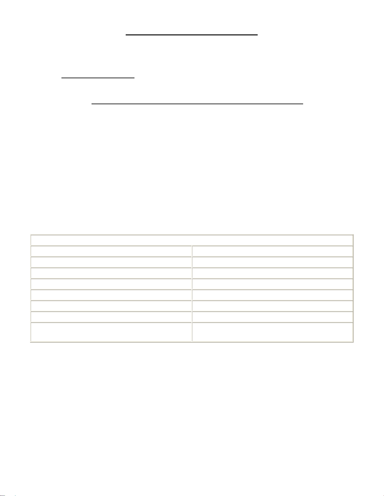
HELLCAT SPECIFICATIONS
Length: 23.5 in
Wing Span: 30 in
Wing Area: 170 in2
Flying Weight: 7.0 ~ 8.0 oz
Wing Loading: 5.93 ~ 6.77 oz/ft2
Power System: GWS DX-A IPS
Functions: Aileron, Elevator, Rudder, & Throttle
Battery Pack: 7 cell 370 mAh NiMH
7.4V ETEC or Kokam Lithium Polymer
What you will need to complete the Hellcat kit:
• Park flyer sized receiver
• Servos (Hitec HS-55 or GWS Pico/Naro) (3 Req. for 4 Channels)
• Speed Control (Castle Creations Pixie 7P or GWS ICS-50 ESC)
• GWS IPS (“A” gearing) and manufacturer recommend propeller
• Dubro Micro E/Z Connectors (5 Req.)
• Dubro Micro E/Z Link (2 Req.)
• 1/2" Dubro Micro Tail Wheel
• 1-1/2” Dubro Micro Lite Wheel (Qty. 2 required)
• 1 roll of Nelson Lite Film AKA Solite covering
• Glue, paint, and other misc. building items
Page 4 of 19
FUSELAGE BUILDING INSTRUCTIONS
 1. Pin fs2 through fs4 on the plan sheet and glue adjacent edges together.
 2. Glue formers (f1 through f9) to (fs2 through fs4) making sure they are perpendicular to
the building surface. You also need to pay close attention to the orientation of all the
formers. For instance, the notch in each former that accepts fs1 should be perfectly in line
when looking down the front of the fuselage.
 3. Align and glue fs1 to the notches of f1 though f9.
 4. Glue the wing saddle ws to f3 through f6 of the fuselage half.
Figure 1
Page 5 of 19
 5. Glue all 3/32" SQ balsa stringers to both fuselage side assemblies noting the end points
of each stringer in Figure 2.
 6. Glue the elevator pushrod exit ps to the fuselage side shown in Figure 2. When each
fuselage half is removed from the building board they may warp ever so slightly, this is due
to the stress the 3/32" SQ balsa stringers introduce on the structure. Do not be concerned,
as the two fuselage halves will straighten each other out when they are joined together.
 7. Glue the fuselage halves together. Be sure to fit the plastic cowling to the front of the
fuselage before covering. The cowling is designed to have a tight friction fit to reduce the
weight of components that might be necessary to hold it on. Sand the circumference of the
front of the fuselage until the plastic cowling has a nice tight fit. The plastic cowling should
slide about 1/8” to ¼” over the front of the fuselage.
Figure 2
Page 6 of 19
 8. Install the cockpit floor cp by gluing it to fs2a, f4, f5 and the 3/32" SQ balsa fuselage
stringers. Refer to Figure 3 for cp's location.
 9. Install the servo tray st by gluing it to f3/f3a and the 3/32" SQ balsa fuselage stringers.
Refer to Figure 3 for st's location.
 10. Build the battery box using the laser cut balsa parts bb1 through bb4 per Figure 3.
When the battery box is complete glue it to the fuselage formers f2/f2a and f3/f3a per
dimension shown in Figure 3.
 11. Glue the 1/4"x1/2" balsa wing mounting block to the fuselage formers f5 and f6. Glue
the 1/4" balsa triangle wing mounting support gusset to the 1/4"x1/2" balsa wing mounting
block and fuselage former f5. This is illustrated in Figure 3.
 12. Laminate the (3) 1/16” thick precut 5/16”x2-7/8” plywood pieces to construct the GWS
IPS mounting stick. Glue the laminated GWS IPS mounting stick to formers f2/f2a and
f3/f3a. This is illustrated in Figure 3.
 13. Remove the section of former f4 shown in Figure 3.
Figure 3
Page 7 of 19
 14. Install the elevator and rudder servos and GWS IPS as shown/described in Figure 4.
Figure 4
Page 8 of 19
 15. Build the elevator and rudder pushrods as shown on the plan page.
 16. Install the thin plywood control horns in the receiving slots in the rudder and elevator
after these control surfaces have been covered. Note this is after the horizontal and
vertical stabilizers have been built.
 17. Refer to Figure 5 for the routing and connection of the pushrods to the servos, elevator
and rudder.
 18. The control rods at the servo end are attached to the servo with the adjustable Dubro
E/Z connector. The control rod wires at the control surface ends are attached by the 1/32”
music wire that passes through the holes in the control horns. Be sure the wires passing
through the control horns extend about ¼” so that the Dubro E/Z Link will retain the control
rod to the control horn. This is illustrated in Figure 5.
Figure 5
Page 9 of 19
WING BUILDING INSTRUCTIONS
Wing Center Section
 1. Cut and pin the bottom 1/8"x1/4" balsa main spar, 1/8"x1/4" balsa servo mounting rails,
3/32" SQ balsa rear spar, wm2, and the 1/16"x1/4" balsa trailing edge stock to the wing
plans on the plans sheet. Note the gap between the servo mounting rails was set per the
dimensions of a Hitec HS-55 servo. You may need to modify the location of these two rails
if you plan to use a different servo manufacturer.
 2. Build the landing gear support rib subassemblies using ribs R4, R4a, and R4b. Note the
differences in each subassembly by referring to Figure 6.
 3. Fit, and then glue R1,R2, R3, R4, R4/R4a/R4b subassembly, and R5 ribs to the
connecting spars and adjacent wood parts making sure that each rib is perpendicular to the
building surface.
 4. Glue the top 1/8"x1/4" balsa main spar to the center section ribs R1 through R5. Note
that this spar must be "cracked" in the center to allow it to follow the taper of the wing's
design. Flood this crack with CA glue after it is glued to the notches of ribs R1 through R5.
 5. Glue the top 3/32" SQ balsa rear spar to ribs R1 through R5. Study the enlarged R5 rib
illustration in Figure 6 for a better look at the spar location in R5.
Figure 6
Page 10 of 19
 6. Glue wm3 to wm2, ribs R1, and trailing edge stock. The hole in wm3 is aligned to the
hole in wm2 as shown in Figure 7.
 7. Glue in the laser cut shear webs sw1 through sw5. Note that the grain of each shear
web runs perpendicular to the building board. The hole in sw1 should be oriented so that it
is closest to the bottom of the wing. This hole accepts the wing-mounting dowel.
 8. Glue the leading edges le1 and le2 to the front of each rib. Align the leading edges so
that they are centered on the front of the ribs.
Figure 7