MOMENT VOYAGER XIV User manual

WARNING! DANGER!
This binding is equipped with systems generang weak magnec elds that could interfere with the
proper funconing of life-saving medical devices such as implanted pacemakers or debrillators
but also magnec cards, watches or compasses.
Keep the binding at a distance of at least 10cm from any device whose proper operaon
could be aected by the magnec eld generated by the systems contained in the binding.
Translated with www.DeepL.com/Translator (free version)
WARNING!
SEAL OF LIABILITY AND REMOVAL OF THE SAME
A “Seal of Liability” has been securely and carefully applied to each binding produced by
The removal of this seal MUST BE EXCLUSIVELY PERFORMED by the original user itself
The removal of the “Seal of Liability” represents the proof of the full, direct, careful and conscious
acknowledgment of the enre content of this “INSTALLATION, USE and MAINTENANCE GUIDEBOOK”
included within the product packagingIn parcular, it represents the full acknowledgment of the
whole parts and paragraphs highlighted by the words “ WARNING!” or “ WARNING! DANGER!”
regarding the risks raising within the use of the product itself for the User and/or third pares and the
producer “PRODUCT LIABILITY LIMITATIONS” clauses
In the event that the “Seal of Liability” is not present on the purchased binding, please DO NOT USE the
product and immediately contact
The “Original User” assumes the absolute responsibility of delivering this “INSTALLATION, USE and
MAINTENANCE GUIDEBOOK” to any secondary users of this product (even if temporary) and to verify
that they have received the correct training on how to use the product as well as having fully and
unequivocally understood the whole parts of this manual
VOYAGER XIV
TOE PATTERN: P3-P3-H1-H1
HEEL PATTERN: H-H-H-H

1| DEFINITION OF THE BINDING’S MAIN PARTS
WHAT WILL YOU FIND INTO THE PRODUCT BOX?
NR2 TOES, NR2 HEELS, NR2 FREERIDE SPACERS (AL09), NR1 “SEAL OF LIABILITY” applied to the product, NR8 TOE SCREWS 13
mm, NR8 HEEL SCREWS 11mm, NR1 “WARNING STICKER”, NR1 “INSTALLATION, USE and MAINTENANCE GUIDEBOOK”, NR2
ski brake’s spacers, NR1 4 MM SPACER
WARNING!
The images included within this manual are purely illustrave. The images may show accessories not included in the product
package, such as adjustment plates. Moment Skis reserves the right to make any changes to the technical or graphic design of
the product at any me.

WARNING! DANGER!
Before proceeding with any operaon regarding the installaon or use of the product, please make sure
that you have fully understood what is wrien and explained in this guidebook.
In case of any doubts and/or uncertaines, please contact Moment Skis:
info@momentskis.com
+1-775-527-1595
WARNING! DANGER!
This binding model
DOES NOT COMPLY WITH ANY DIN/ISO SAFETY STANDARD NOR ANY SAFETY CERTIFICATIO
In parcular, this binding does not comply with DIN/ISO 11088and/or DIN/ISO 13992 safety standards.
Therefore, the release systems oered by the binding could fail in releasing the boot when necessary
and/or expected with a consequent danger for the User’s safety.
2| GENERAL WARNINGS AND RECOMMENDATIONS
Please, be aware that ski-mountaineering, like many other high mountain acvies, is a DANGEROUS
SPORT, that may cause injuries to the ski mountaineer itself and/or third-party.
WARNING! DANGER!
This binding is conceived, developed and produced for FreeTouring acvies. The high performance
and the extreme lightness of this product can inuence and/or reduce the safety features of
the product itself, including the quality or repeatability of the boot release in the event of a fall.
This binding can only be used in combinaon with Alpine Touring boots, provided with standard “tech”
inserts and general geometries that comply with market standards.
This binding heel part oers adjustable release systems with values in between 8 to 14. Calibrang the
most suitable release value for the User’s characteriscs may reduce the risk of injuries to the lower
The user, by removing the "SEAL OF LIABILITY" from the binding, consciously assumes all the
responsibility raising from the use of this product, and therefore releases Moment Skis from any damage
caused to himself and/or third pares during the use of the product.

In the pracce of ski mountaineering, dangerous and/or unpredictable situaons may occur; never
overesmate your capabilies, never ski if sick of wounded or under the eect of alcohol, medicines or
drugs.
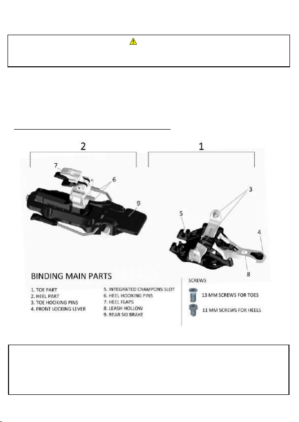
Voyager XIV bindings are realized for, and tested in combinaon with, boots provided with standard “TECH
INSERTS” in perfect state and original dimensions; the use of boots with NON-STANDARD and/or worn
“TECH INSERTS” could modify the funconal performance of the bindings and create a great danger for the
User. Before any use check the general condion of the gear: in case of doubts immediately reach a
“SPECIALIZED TECHNICIAN” (denion at chapter 3)for a deeper check or a VOYAGER dealer.
Installaon, adjustment and calibraon operaons on these bindings must be exclusively performed by a
“SPECIALIZED TECHNICIAN”: any operaon performed by a “NON-SPECIALIZED TECHNICIAN” is strongly
un-recommended and could lead to greater risks for the User’s safety.
During transport (ex: car roof, backpack, bike) the bindings could be aacked by dirt or salt that may
damage the bindings or modify the regular funconing of the same: always protect the bindings with
adequate instruments by these external agents during transport.
Aer hooking the boot, always check that the toe pins are correctly matching with their seats on the TECH
INSERTS by rotang the boot a few mes on the toe piece, as shown at chapter 4.
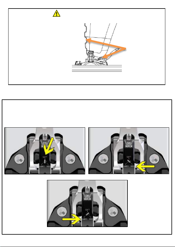
Before skiing, please remember to place the toe front lever in downhill posion, checking that the “ SKI”
logo marked on the front lever is fully visible. Skiing with the front lever in uphill posion eliminated the
lateral release funcon of the binding with greater risks for the User’s safety. A release of the toe with the front
lever locked in uphill mode can
lead to heavy structural damages to the product, with consequen
greater danger for the user (please check paragraph 43).
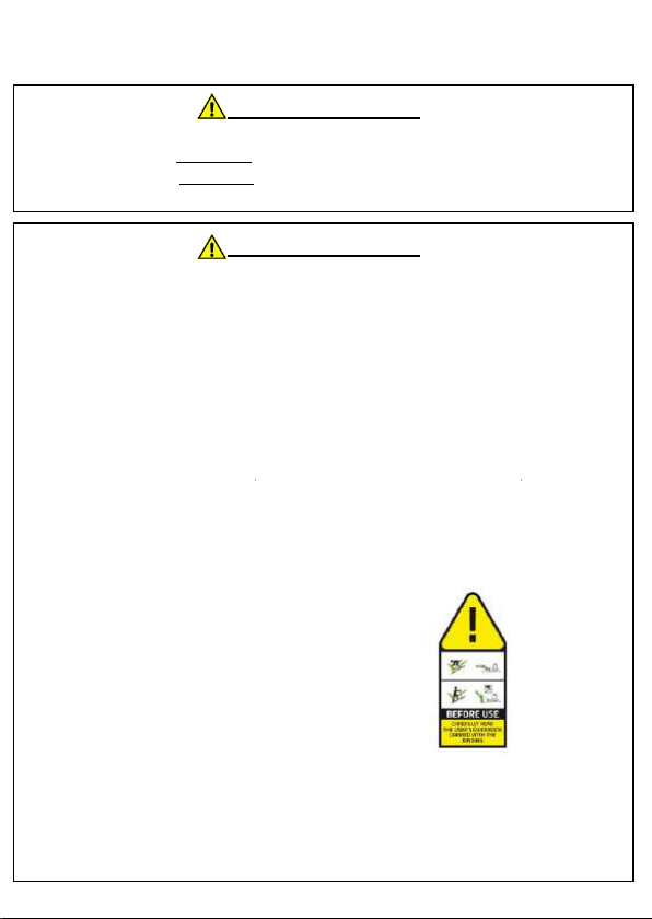
Before each use check that the binding or the accessories do not have defecve, worn or damaged parts,
that the release system is perfectly working and that the bindings have not been contaminated by debris or
ice/snow.
Never use bindings with damaged parts: if there is any defecve or broken part, or any doubt is raising in
your mind in regards to the state of your bindings, immediately stop the use of the product and promptly
Frequently check (each 30 days of use or immediately aer each extraordinary event, such as bad falls)
that: 1) the binding is correctly xed to the ski 2) that the screws are correctly ghtened 3) the ski internal
structure is not damaged 4) the ski is at in the binding mounng area in order to
the binding base plates. If one or more of these condions are not conrmed, or cannot be conrmed
by the User, please immediately stop the use of the ski-set and promptly deliver it to a SPECIALIZED
TECHNICIAN for a deeper check or to an a dealer to start a warranty claim.
The use of a ski brake (REAR brake included with the binding) or a leash (“KEVLAR® CORE LEASH”)
is strongly recommended, in order to limit the risk of losing the skis and/or create damages to the
gear or third pares.
In case of deep fresh snow or hard snow, the eciency of any SKI BRAKE is very limited: in these snow
condions the use of a KEVLAR® CORE LEASH is strongly recommended.
Any MODIFICATION to components and NON-PROPER USE of any Voyager XIV binding may invalidate the
product warranty and raise the risk of injuries for the user and/or third-party
The use of non-original Voyager accessories may cause damages to the bindings with greater risks for the user.
Safely keep these user’s guide and check it in case of any doubt.

3| INSTALLATION, ADJUSMENT AND CALIBRATION
1
| INSTALLATION
WARNING! DANGER!
These bindings and the connected accessories can be exclusively installed, adjusted or calibrated by a
“SPECIALIZED TECHNICIAN”
A “SPECIALIZED TECHNICIAN” is any technician operang in the ski/ski touring business eld provided with
the following minimum requirements:
1) Is in possession of the original ATK® “AUTOMATIC DRILLING JIG” addressed to the installaon of the
product and has perfectly understood the enrety of the respecve guidebooks. (WARNING! The
Specialized Technicians shall be in possession of the latest release of the Drilling Jig Guidebook, which
can be found at the momentskis.com
2) Is in possession of the experience, know-how and skills raising from years of pracce in the eld of
“TECH” bindings installaons, adjustment and calibraon.
3) Is in possession of the whole instruments and tools needed to perform a perfect installaons,
adjustment and calibraon of a Voyager XIV ski touring “TECH” binding, including the specic tesng
machinery needed to check the real and correct release performance of the binding.
The “SPECIALIZED TECHNICIAN” shall:
1) Perfectly install, adjust and calibrate the product and its
accessories.
2) Deliver the product to the “Original User” including the
“SEAL OF LIABILITY”, sll complete and correctly applied
to the product.
3) Check that the “WARNING STICKER” is properly applied to
one of the two skis in front of the toe piece area.
4) Deliver this “INSTALLATION, USE and MAINTENANCE GUIDEBOOK” to the “Original User”.
The installaon, adjustment and calibration of a Voyager XIV binding is forbidden by any technician that
does not meet all 3 above menoned minimum requirements, due to the greater risk of incorrect
installaon, adjustment and calibraon.
WARNING! DANGER!
TOE PIECE SCREWS MAX TORQUE: 7 N/m
HEEL PIECE SCREWS MAX TORQUE: 5 N/m
A wrong seng distance in between boot and binding may create an early and sudden fail of the binding, creang irreparable
damages to the ski/binding/boot system and/or eliminate/modify the release funcon in case of fall with consequenal
damages to the athlete and third pares.
Always check that the penetrang lenght of the screws ts the depth of the drilled holes, and anyway with the height of the ski
in the mounng area; otherwise, use proper screws or contact ATK® at info@atkrace.com .
The binding must be installed only ON NEW SKIS, which present an absolutely at mounng area and a structural reinforce for
the screws ghtening and anchoring.
Each boot has its own substanal geometry: always use the boot used for installaon, setup and check of the correct
funconality of the binding in combinaon to the binding itself

| ADJUSTMENT
1| ADJUSTMENT: HOW TO ADJUST THE HEEL PART POSITION
1. Hook the boot to the toe part.
2. Adjust the heel part on the plate
by adjusng the back screw to obtain
aposion of the heel pins that allows
the boot to step in.
3. Step into the heel part with the boot
and insert the 4 mm gauge in
between boot and heel.
4. Micro-adjust the heel posion and
eliminate any free room in between
gauge, heel and boot.
WARNING! DANGER!
The binding model VOYAGER XIV is provided with a
“E.R.S.” system (ELASTIC RESPONSE SYSTEM),
developed to support an aggressive and hard
charging skiing style with an elasc response to
compressions and jumps, improving the ski
control, precision and ex performance. (8mm)
“RS” does not eliminate the need of a gap of
4 mm in between boot and heel: to respect the
imposed distance is a compulsory point in order
to avoid undesired malfuncons and /or
damages to the material, with consequent
dangers for the user or third pare
The adjustment operaon must be done manuallyby using a good quality PH2 screwdriver
The adjustment range provided by the plate is 25 mm (0,+14mm,-11mm); the adjustment range is marked
by a scale and included within two “STOP” logos.
During the adjustment operaons it is ABSOLUTELY FORBIDDEN to obscure the two side lines marked
with the “STOP” log
Using the heel with an over range adjustment could lead to malfuncons and/or structural damages to
the binding with possible greater dangers for the User
A incorrect installaon distance between boot and binding (smaller than 4 mm or bigger than 5 mm) can
cause an early or sudden structural failure of the binding with irreparable damages to the binding/ski/boot
system and/or prevent or compromise the release performance in the event of a fall with consequen
greater risks for the athlete or third pares.

5. Completely release the boot and step in again to doublecheck with the 4mm gauge that the boot-heel
distance is correct: the gauge must enter the space without forcing and there must not be any l room in
between boot, gauge and heel. (Pictures 1, 2, 3)
ADJUSTMENT: BOOT-BINDING COMPATIBILITY CHECK
WARNING! DANGER!
Bellowed touring boots or NTN standard boots with TECH inserts are NOT COMPATIBLE WITH ANY
VOYAGER XIV TOURING BINDING
In walk mode, the contact point in between the boot and the front locking lever must not exceed the
vercal line marked at PICTURE 4 and 5
PICTURE 4 shows a boot which is COMPATIBLE with the binding: the boot p gets in touch with the
front lever in a point behind the vercal line marked on the picture.
PICTURE 5 shows a boot which is NOT COMPATIBLE with the binding: the boot p gets in touch with
the front lever in a point over (even if slightly) the vercal line marked on the picture.
The use of a NON-COMPATIBLE boot-binding combinaon is strictly FORBIDDEN, due to the high
risk of an undesired and/or accidental acvaon of the front locking lever of the binding that may be
moved from UPHILL WALKING MODE to DOWNHILL SKIING MODE during the uphill walking phase
with a great danger for the User’s safety
PICTURE 4
PICTURE 5
PICTURE 1
PICTURE 3
PICTURE 2

3| ADJUSTMENT: HOW TO ADJUST THE “UHV SYSTEM
The “U.H.V” system provides a locking hardness variaon to perfectly t with the dierent styles of boots
inserts and user’s needs. By adjusng the selector in “So”, “Mid” or “Hard” posion, the force needed to
lock the front lever will increase or decrease. At the same me, the pins on the boot insert will increase
or decrease.
WARNING! DANGER!
Hook the boot at the binding and
set it for the uphill walking mode.
Rotate the boot on the toe up to
the front end of the rotaon-
range and verify that the boot is
performing at least a 90° free
rotaon.
If the free rotaon range is smaller
than 90°, the boot p and/or the
front part of the binding could be
damaged by a regular use of the
set.
BOOT FREE
ROTATION
RANGE >= 90°

WARNING! DANGER!
This binding model
DOES NOT COMPLY WITH ANY DIN/ISO SAFETY STANDARD NOR ANY SAFETY CERTIFICATIO
In parcular, this binding does comply with DIN/ISO 11088and/or DIN/ISO 13992 safety standards.
The release values set on the binding must be considered as INDICATIVE: the real release value may
sensibly dier from the shown one, variate during the enre life of the product and/or variate
according to the use and/or wear and tear condions.
These bindings oer a VERTICAL RELEASE SYSTEM (My) and a LATERAL RELEASE SYSTEM (Mz), both
driven by the heel part and fully independent.
These bindings oer a release value adjustment range in between 8 and 14. Calibrang the most
suitable release value for the User’s characteriscs may reduce the risk of injuries to the lower
.
Calibrang an underesmated release value could lead to undesired pre-releases of the binding or
auto-rotaons of the heel during the ascent phase and increase the risk of injuries for the User
The vercal release takes place thanks to the radial divaricaon of the two hooking pins under the
eect of a sucient vercal extracon load. This release is driven by an independent elasc system.
The lateral release takes place thanks to the rotaon of the heel head under the eect of a sucient
lateral load. This release is driven by an independent elasc system.
These bindings do not provide any dierent release than vercal (My) and lateral (Mz) ones.
While skiing, the front locking lever of the binding must be set in “DOWNHILL MODE”. Skiing with
the front lever set in “UPHILL MODE”, the lateral release system is completely disabled, with a
greater risk for the user. (check out paragraph 4.3)
| RELEASE SYSTEMS

WARNING! DANGER!
The adjustment of the release systems can be performed exclusively by a
“SPECIALIZED TECHNICIAN”
The adjustment of the release systems must be performed accordingly with the physical and performance
characteriscs of the User.
Aproper calibraon of the release systems may reduce the risk of injury to the inferior limbs under the
femur.
The release value must fall in between the maximum and minimum release value oered by the
adjustment scale; the adjustment screw shall never overpass the “STOP” logo laser engraved on the side
of the minimum and maximum release values available on the adjustment scale
Before proceeding with the release test on the tesng machine, remember to lubricate or humidify the
brake in the contact area between the brake pad and boot sole in order to avoid fricons that might
invalidate the release test.
WARNING! Each boot has its own substanal geometry and the installaon, adjustment and calibraon of
the binding must be performed with the boot that will be used in combinaon with the binding itself. In
case of boot replacement (with a dierent one in model or size), a “SPECIALIZED TECHNICIAN” must
check the adjustment and calibraon of the binding according to the new boot. If it is not possible to set
or adjust the binding for the new boot, a completely new installaon, adjustment and calibraon is
required.
1| RELEASE SYSTEMS SETTING
1| VERTICAL RELEASE SYSTEM CALIBRATION (My)
The vercal release system
adjustment can be performed
through the screw on the top of the
heel head (PH2 good quality insert)
(PICTURE ON THE SIDE)
The yellow pointer top border shows
the vercal release value set on the
binding. (PICTURE ON THE SIDE: EG
value “8”)
Turn clock-wise the adjustment screw to increase the release value
Turn counter clock-wise the adjustment screw to decrease the release value

WARNING! DANGER!
It is highly recommended to strictly follow the operaons described and illustrated in this chapter: a
misunderstanding or execuon of these procedures may create a greater risk for the user and/or
third pares, such as damages to the gear itself.
Before proceeding with any operaon or use, verify that the boots and the bindings are
COMPLETELY FREE from ice, dirt, debris or any other foreign body that may lead to a failure in the
regular funcons of the bindings.
Before proceeding with any operaon, check the funconal state and the wear condion of the
binding and its components: in case of doubts regarding the perfect funconality of one or more of
the binding’s components, immediately stop using the product and promptly reach a “SPECIALIZED
TECHNICIAN” for a deeper check or a Voyager XIV dealer.
Some funcons of the binding can be handled with a ski pole. The use of a ski pole may create
scratches and/or an early wear of the product surfaces.
The binding includes some powerful elasc systems. An involuntary, wrong or accidental acvaon of
these system is dangerous for the User’s or third party’s safety. Always handle these bindings with
the proper care.
Keepthese bindings out of reach of children
2| LATERAL RELEASE SYSTEM CALIBRATION (Mz)
The lateral release system
adjustment can be performed
through the back screw shown by the
PICTURE ON THE SIDE (use a good
quality PH2 or PZ3 insert). The set
release value is shown through the
upper window (PICTURE ON THE
SIDE, egvalue “5”)
Turn clock-wise the adjustment
screw to increase the release
value
Turn counter clock-wise the
adjustment screw to decrease the
release value
4| PRACTICAL USE INSTRUCTIONS

WARNING! DANGER!
Before proceeding with your acvies, always check the proper lubricaon of the brake’s arms recall
walls in order to avoid malfuncons (see at chapter 5).
Any operaon on the brakes must be performed MANUALLY!
| HOW TO USE THE REAR SKI BRAKES
1 WALK/UP-HILL MODE
1) From ski mode (PICT6), manually press on the side buon, moving it to the end of its sliding range (PICT7)
2) Keeping the side buon in the reached posion, manually push the brake pedal all the way down towards
the ski (PICT8)
3) From the reached posion, release the side buon and then the brake pedal that will be stabilized in walk
mode by the side buon (PICT9)
PICTURE 6
PICTURE 7
PICTURE 8
PICTURE 9

WARNING! DANGER!
In this mode, the toe part is locked on the boot. This means that in case of fall, avalanche or any
other unlucky situaon that can be faced by the user, the release of the boot will be nearly
impossible. This condion represents a GREAT DANGER for the user that could be dragged into an
avalanche by the ski and/or suer serious injuries in case of fall or accident.
When the binding is set in up-hill mode, the separaon between boot and binding can only occur in
case of heavy material deformaons due to an event, external load or parcular stress: if this
happens, immediately stop using the product and promptly reach a “SPECIALIZED TECHNICIAN” for a
deeper check or a VOYAGER XIV dealer.
During the ascent, an accidental impact or any other parcular event, may move the front locking
lever of the binding from the uphill walking mode to the downhill skiing mode. This represents a
great danger for the user’s safety that may experience an undesired boot release, with consequent
risk of falling or slipping in dangerous condions: frequently check the correct seng and
stabilizaon of the front lever of the binding, especially in case of accidental impact
2 SKI MODE
In order to set the brake in ski mode starng from
the walk mode, operate as follows (PICT10):
1) Push the brake pedal all the way down to the ski.
2) Push the side buon up to the end of its sliding
range.
3) Release the brake pedal.
4) Release the side buon.
5) Proceed with the desired acvies.
| UP-HILL/WALKING MODE
PICTURE 10

Set the ski brake in walk mode as shown at paragraph 4.1.1
Posion the heel part in one of the conguraons shown at “PICTURE 11”, rotang manually the heel
head and stabilizing the heel aps into its seats.
PICTURE 11

Check that the toe part is
in the posion shown at
PICTURE 12, ready to
receive the boot, free
from ice, snow or other
debris. If toe is not in the
proper posion, manually
press on the front locking
lever in order to reach
the stabilized posion
shown at PICTURE 12
Move the boot p towards the toe part, matching the front TECH insert seats with the toe hooking pins
(PICTURE 13)From this posion, vercally push on the toe part to step in. (PICTURE 14/15)Rotate a
few mes the boot in order to check the proper boot-binding coupling, as shown at PICTURE 15
PICTURE 13
PICTURE 12
PICTURE 14
PICTURE 15

Slightly pull the front locking lever towards the boot p up to the uphill stabilized posion in order to
lock the binding on the boot and allow the ascent, as shown at PICTURE 16
WARNING! Before approaching any up-hill, always check that the front locking lever is stabilized in the
locked posion (WALK), as shown at PICTURE 17. The marked line should match with the “WALK” lines.
PICTURE 16
PICTURE 17

WARNING! DANGER!
The correct seng of the binding for the DOWNHILL MODE is explained at paragraph 5.2 of this
manual. This use mode may allow the release of the binding in case of ruinous falls: NEVER SKI
with the binding set for the UP-HILL WALKING MODE in order to avoid the deacvaon or exclusion
of the release systems of the binding!
It is absolute responsibility of the user to decide which behaviour/use modality represents a
MINOR RISK for its own safety and that one of third pares, according to the faced condion
While skiing, an accidental impact or any other parcular event, may move the front locking lever of
the binding from the downhill skiing mode to the uphill walking mode. This can happen suddenly and
without any voluntary acon of the user: frequently check the posion of the front locking lever,
especially in case of accidental impact.
| DOWN-HILL MODE
Move the heel on the stabilized posion
shown at PICTURE 18 by rotang the
heel head with the hands. Then rotate
the heel ap towards the ski tail up to
the back end of the rotaon range.
Check that the toe part is in the posion
shown at PICTURE 19, ready to receive the
boot, free from ice, snow or other debris. If
toe is not in the proper posion, manually
press on the front locking lever in order to
reach the stabilized posion shown at
PICTURE 19.
PICTURE 18
PICTURE 19

Move the boot p towards the toe part, matching the front TECH insert seats with the toe hooking pins
(PICTURE 20). From this posion, vercally push on the toe part to step in. (PICTURE 21/22). Rotate a
few mes the boot in order to check the proper boot-binding coupling, as shown at PICTURE 22.
Check that the front locking lever is in downhill skiing mode (SKI), as clearly shown at PICTURE 23The
marked line should match with the “SKI” linesIf not like that, slightly push on the front locking lever in
order to obtain the proper posion, as shown at PICTURE 23
PICTURE 23
PICTURE 20
PICTURE 21
PICTURE 22

WARNING! DANGER!
Before your downhill secon, it is really important to check that the perfect coupling in between boot
and binding has occurred. It is common and good behaviour to check the proper toe pin inseron into
the boot insert by locking the toe front locking lever and then immediately move it back into the
downhill mode.
In case that the locking operaon has been dicult or impossible, it is strictly forbidden to proceed with
the downhill secon and it is recommended to act as follows:
-Check that the boot tech insert is fully free from ice and dirt, otherwise clear it carefully.
-Check that no ice has built up underneath the toe piece locking mechanism, otherwise
carefully clear it out using a knife or a thin secon tool.
Aer these operaons, please repeat the above-menoned test to check the perfect coupling in
between the toe piece and boot insert.
Before starng with your downhill secon, always doublecheck that your toe piece has been set back
into downhill mode
Press on the heel part of the binding in order to step in and to obtain the complete hooking of the boot,
as shown at PICTURE 24
PICTURE 24

WARNING! DANGER!
While releasing the binding, rmly hold the ski that is going to be release from the boot in order to
avoid an uncontrolled ski loss that would represent a great danger for the skier and/or third pares
which may be hit by the ski.
At the end of your ascent, carefully release the boot from the binding and immediately turn the ski
brake in braking mode (downhill mode) in order to reduce the risk of an uncontrolled ski loss.
| HOW TO GET OUT FROM THE BINDING
By the up-hill posion, press on the
front locking lever as show at
PICTURE 25, moving it to the
downhill skiing posion and proceed
as follows.
By the downhill skiing posion, press
again the front locking lever as
shown at PICTURE 26, in order to
fully open the toe part and release
the boot.
Liand rotate the foot p moving
the boot forward in order to get out
from the heel part of the binding, as
shown at PICTURE 27.
PICTURE 27
PICTURE 26
PICTURE 25
Table of contents
Popular Safety Equipment manuals by other brands

Falltech
Falltech 5029B User instruction manual

CMC
CMC ATOM HARNESS manual

MSA
MSA Latchways PushLock Eyebolt User instructions

schmersal
schmersal AES 1235 operating instructions

Guardian Fall Protection
Guardian Fall Protection Angel Anchor instruction manual

Singing rock
Singing rock PATRON LANYARD Instructions for use