Lasermet LS-10-12 User manual

LS-10-12 Laser Beam Shutter Instruction Manual
CEB00XXX-53-000 Issue 3 19 January 2021
LASERMET
LS-10-12 SHUTTER
INSTRUCTION MANUAL
LASER BEAM SHUTTER

LS-10-12 Laser Beam Shutter Instruction Manual
CEB00XXX-53-000 Page 2 of 9 Issue 3 19 January 2021
LASERMET LS-10-12
Instruction Manual
Contents
1 Declaration of Conformity .................................................................................................. 3
2 Safety Warnings .................................................................................................................. 4
3 Concept ............................................................................................................................... 5
4 Installation .......................................................................................................................... 5
5 Wiring ................................................................................................................................. 5
6 Operation ............................................................................................................................ 6
7 Specifications ...................................................................................................................... 7
8 Warranty ............................................................................................................................. 8
9 Contact Details .................................................................................................................... 9

LS-10-12 Laser Beam Shutter Instruction Manual
CEB00XXX-53-000 Page 3 of 9 Issue 3 19 January 2021
1 Declaration of Conformity
LASERMET LIMITED
LASER BEAM SHUTTER
Part no. LS-10-12
DECLARATION OF CONFORMITY
This is to certify that the Laser Beam Shutter designated by Lasermet Part Number LS-
10-12 has been tested in accordance with the following directives and standards and
found to comply.
Lasermet certifies that this product complies with the basic requirements for health
and safety as provided by the following directives and standards:
Directives: Machinery Directive 2006/42/EC
Standards: EN 60825-4:2006 +A1:2008 +A2:2011
Safety of Laser Products, Part 4 – Laser Guards
The relevant Protective Exposure Limits are:
Irradiated Area
PEL (T2) 100s
4 mm2
5 MW/m2
Supplier:
Lasermet Limited
Lasermet House
137 Hankinson Road
Bournemouth
BH9 1HR
Dorset
United Kingdom
Country of Origin: England
Date: 10 June 2019

LS-10-12 Laser Beam Shutter Instruction Manual
CEB00XXX-53-000 Page 4 of 9 Issue 3 19 January 2021
2 Safety Warnings
This device is intended to be used as part of a safety system which may be used to protect personnel
and equipment from possible injury, damage, or loss.
As such it must be installed and wired according to these instructions and tested by suitably qualified
persons. No attempt may be made to tamper with the parts, open them, or use them outside of the
parameters contained herein.
The units are only designed to be fixed to surfaces using their inbuilt fixing holes. They must not
come into contact with each other or any other moving part when in use. The parts should never be
subject to impact or mechanical strain.
Safety switches should never be defeated or bypassed. It is imperative that all steps are taken to
ensure that any spare actuators are made unavailable, such that they cannot be used to defeat the
switch or reduce the protection offered by the system in any way.

LS-10-12 Laser Beam Shutter Instruction Manual
CEB00XXX-53-000 Page 5 of 9 Issue 3 19 January 2021
3 Concept
The LS-10-12 is a laser beam shutter and beam dump designed specifically for safety applications. It
can, however, also be used for beam control (i.e. turning a laser beam on and off). When used for
safety applications the electrical power to the LS-10-12 must be supplied by an interlocked shutter
supply such as the Lasermet ICS-6. It will then provide fail safe interlocking of the laser beam to
protect persons entering the laser area from the laser beam hazard.
The LS-10-12 is designed as a combined shutter and beam dump and will not reflect the beam back
out of the shutter. Consequently, there is no requirement for an additional beam dump. When used
for safety interlocking the shutter input tube should be butted up against the laser to totally enclose
the beam and ensure that there is no accessible laser beam when the shutter is closed.
This beam shutter is gravity fed and not reliant upon springs, electrical power or any other drives or
devices for return to the safe mode.
Lasermet provides a full range of laser interlock equipment including control systems, interlock
switches, illuminated warning signs, laser shutters, door locks, external power supplies etc. which
can be connected to provide a complete laser interlock system. Full support, design and installation
is available from Lasermet, please contact us for any queries. Contact details are given at the end of
this manual.
4 Installation
Mount the LS-10-12 in front of the laser aperture with the ‘Beam input’ side facing the laser
aperture. For safety interlocking applications, if there is any space between the laser aperture and
the shutter input tube, metal tube must be used to enclose the beam. The shutter must be mounted
vertically with its face perpendicular to the laser beam. There is an M6 thread in the base for
mounting on an M6 optical stem.
5 Wiring
The Shutter is equipped with a 9-way male ‘D’ connector. The pin connections on the shutter are as
follows:
Pin Function
1 +12 to 24V DC power to shutter
2 0V
3 Remote open input
4 Not Used (Internally connected to pin 1)
5 ‘Open’ status output
6 ‘Closed’ status output
7 - 9 Optional electrical Interlock option - see below.

LS-10-12 Laser Beam Shutter Instruction Manual
CEB00XXX-53-000 Page 6 of 9 Issue 3 19 January 2021
A switched shutter power supply is required. Connect pin 1 to the +ve side of the supply and pin 2 to
0 Volts. The shutter can be opened and closed using its buttons when the supply is present. When
the supply is removed, the shutter closes.
If using remote control with a switched supply, connect the switched supply + to pins 1 and 3 and –
to pin 2. The shutter will open immediately the supply is turned on.
If using remote pushbuttons to control the shutter use a normally closed button in series with the
supply for the ‘Close’ function, and a normally open pushbutton between pins 1 and 3 for the ‘Open’
pushbutton. Both switches need only switch for approximately 0.25 s to close or open the shutter.
The existing pushbuttons will still work as normal. A remote switching unit with indication LEDs (part
number LS-RS) is available from Lasermet. While the switched supply is present, the shutter status is
indicated on LEDs on the unit and is available as an indication contact if the optional interlock option
is ordered. Contact Lasermet for other control methods.
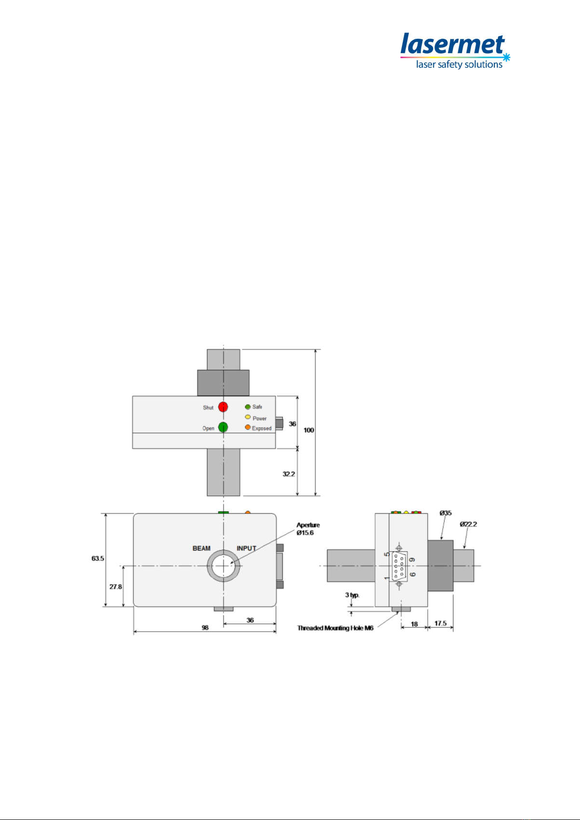
6 Operation
When the power supply to pin 1 of the shutter comes on, the middle yellow LED will light. The green
LED will also light indicating that the shutter is closed. Pressing the green button momentarily will
open the shutter. The Orange LED will light indicating that the shutter is open, and the beam is
exposed. To manually close the shutter, press the red button. Loss of power to the shutter, such as
when a door interlock switch trips the interlocked power supply, will also cause it to close.
Status Outputs – pins 5 and 6
When the shutter is open, the power supply voltage is output on connector pin 5. When the shutter
is closed, the power supply voltage is output on connector pin 6. The maximum load that may be
placed on these outputs is 100mA non-inductive. If connecting them to an inductive load such as a
relay coil, a diode should be fitted across the load with the anode to 0V.
Optional Interlock – pins 7, 8 and 9
These connections are reserved for an optional internal electrical interlock board (part no: LS-10-IB)
which provides two volt-free contacts indicating the state of the shutter. This factory-fitted option
may be specified at time of ordering.
LED Indicator Lamps
Green Shutter closed
Yellow Power On
Orange Shutter open – beam exposed

LS-10-12 Laser Beam Shutter Instruction Manual
CEB00XXX-53-000 Page 7 of 9 Issue 3 19 January 2021
7 Specifications
Supply Voltage 12 – 24VDC (9 – 25VDC)
Current Consumption 180mA max. at 12VDC
Status Output Voltage As incoming supply
Status Output Current Rating 100mA max. non-inductive
Optical Specification
Maximum Optical Power 20W ave.
Maximum Beam Diameter 15mm
Maximum Power Density as per DoC
Dimensions
Dimensions are approximate. Values given as ‘typical’ are average values measured across a number
of samples and are not guaranteed. Lasermet reserve the right to alter any specification without
prior notice.

LS-10-12 Laser Beam Shutter Instruction Manual
CEB00XXX-53-000 Page 8 of 9 Issue 3 19 January 2021
8 Warranty
Lasermet provide a 12-month warranty for defects in materials and manufacture, from the date of
installation or delivery. Installations completed by Lasermet are covered against defects in
workmanship for 12 months.
Damage or defects caused by other factors are not covered. For example, industrial contamination,
incorrect cleaning, storm damage. Consequential loss is not covered under warranty. Compensation
for indirect or direct loss or damage is expressly excluded. Rectification of the defects or a
replacement does not initiate a new warranty period.
For all deliveries, payments and other legal transactions, English law takes precedence for any
litigation.

LS-10-12 Laser Beam Shutter Instruction Manual
CEB00XXX-53-000 Page 9 of 9 Issue 3 19 January 2021
9 Contact Details
Lasermet provide a full range of laser interlock equipment including interlock switches, illuminated
warning signs, laser shutters, entry keypads with built-in fail-safe override timer, door locks, external
power supplies etc. which can be interconnected to provide a complete system. We also supply
equipment and consultancy covering all aspects of laser safety. Full support, design, and installation
is available from Lasermet, please contact us for any queries.
For sales and technical support:
Lasermet Ltd.
Lasermet House,
137 Hankinson Road,
Bournemouth
BH9 1HR
United Kingdom.
Tel: +44 (0) 1202 770740
Fax: +44 (0) 1202 770730
Website: www.lasermet.com
Lasermet Inc.
10N Martingale Road, Suite 400,
Schaumburg, Illinois 60173
United States.
Tel: 847 466 1475
Website: www.lasermet.com
Table of contents
Other Lasermet Safety Equipment manuals
Popular Safety Equipment manuals by other brands

MSA
MSA V-GARD 900 Series operating manual

Climbing Technology
Climbing Technology SPARROW 200 manual

Climbing Technology
Climbing Technology ASCENT PRO manual

KStrong
KStrong KAPTURE ELITE LV2 User instruction manual

Sellstrom
Sellstrom DP4 Assembly, operating, and maintenance instructions

MSA
MSA SUPREMA Operation manual